1
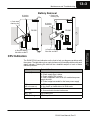
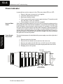
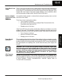
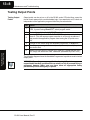
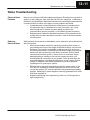
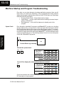
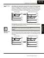
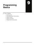
Maintenance and
Troubleshooting
113
In This Chapter. . . .
— Maintenance
— CPU Indicators
— Power Indicator
— RUN Indicator
— CPU Indicator
— BATT Indicator
— Expansion Base Power
— Testing Output Points
— I/O Module Troubleshooting
— Noise Troubleshooting
— Machine Startup and Program Troubleshooting
13--2
Maintenance and Troubleshooting
Maintenance
Maintenance and
Troubleshooting
Maintenance and
Troubleshooting
Maintenance and
Troubleshooting
The DL305 is a low maintenance system requiring only a few periodic checks to
ensure your system stays up and running without problems. There are two things
you should check periodically.
S Air quality (cabinet temperature, etc.)
S CPU battery
Air Quality
Maintenance
The quality of the air your system is exposed to can affect system performance. If
you have placed your system in an enclosure, check to se the ambient temperature
is not exceeding the operating specifications. If there are filters in the enclosure, you
should clean or replace them as necessary. A good guideline is to check your system
environment every one to two months and make sure the environment meets the
system operating specifications.
CPU Battery
Replacement
The CPU battery is used to retain the application program, data register, and
retentive memory types. The life expectancy of this battery is five years.
NOTE: Before replacing your CPU battery, you should back-up your application
program. This can be done by saving the program to hard/floppy disk on a personal
computer or using the handheld programmer along with a cassette tape recorder.
The CPU has a built-in capacitor to retain the memory for several minutes while the
battery is being replaced. Saving the program prior to replacing the battery is just an
added precaution.
WARNING: If the battery connector is not connected to the PC board or the
battery is left out of the system, the indicator light will not notify you of the
error. Be sure the battery is in place and the connector is firmly seated before
you place the CPU back into the base.
DL330, DL330P,
To replace the CPU battery:
DL340 CPU Battery
1. Turn power off to the system.
Replacement
2. Wait 60 seconds then remove the CPU. Do not short any connectors or
components on the CPU since it may alter the program memory.
3. Unlatch and tilt the clip covering the battery.
4. Pull the two wire battery connector from the PC board.
5. Remove the battery.
WARNING: Do not attempt to recharge the battery or dispose of it by fire. The
battery may explode or release hazardous materials.
To install the CPU battery:
1. Plug the (keyed) two wire battery connector on the battery into the
connector on the PC board.
2. Push gently till the connector snaps closed
3. Slide the battery under the battery retaining clip till the battery is positioned
in the socket.
4. Push the retaining clip down over the battery snapping the clip over the
edge of the PC board.
5. Note the date the battery was changed.
DL305 User Manual, Rev. D
Maintenance and Troubleshooting
13--3
Battery Removal
2) Unplug
connector
1) Push back
retaining clip
1) Push back
retaining clip
2) Unplug
connector
DL330
DL340
RAM/UVPROM
3) Remove battery
Part #D3--04--BATT
CPU Indicators
The DL305 CPUs have indicators on the front to help you diagnose problems with
the system. The table below gives a quick reference of potential problems with each
status indicator. Following the table will be a detailed analysis of each of these
indicator problems.
Potential Problems
Power (off)
1. Improper wiring
2. Power supply fuse is blown
3. Power supply/CPU is faulty
4. Other component such as an I/O module has power
supply shorted
5. Power budget exceeded for the base power supply
RUN
(will not come on)
1. CPU programming error
2. Key switch on handheld not in RUN mode
CPU (on)
1. CPU defective
2. Severe electrical noise interference
BATT (on)
CPU battery low
BATT (flashing)
CPU in update mode
DL305 User Manual, Rev. D
Maintenance and
Troubleshooting
Indicator Status
Maintenance and
Troubleshooting
3) Remove battery
Part #D3--04--BATT
13--4
Maintenance and Troubleshooting
Power Indicator
Power Supply
Blown Fuse
The fuse for base power is located behind the power supply cover at the right side of
the base.
1.
2.
3.
4.
5.
Remove power from the base.
Remove the two slotted insert screws from the front cover.
Remove and replace the 2A 250V fuse. (4A 250V for the DC models)
Place the front cover back on the power supply and insert the screws.
Reapply power to the system.
Fuse (2A)
(4A for DC models)
Maintenance and
Troubleshooting
Maintenance and
Troubleshooting
Incorrect Base
Power
In general there are four reasons for the CPU power status LED to be OFF:
1. Power to the base is incorrect or is not applied.
2. The power supply has a blown fuse.
3. Base power supply is faulty.
4. Other component(s) have the power supply shut down. This problem could
be in the base or in the I/O modules.
5. Power budget for the base has been exceeded.
If the voltage to the power supply is not correct, the CPU may not operate properly or
may not operate at all. If this is a new installation, first check the terminal strip on the
local CPU base to insure the base is wired correctly. If it is wired for 110 VAC while
using 220 VAC the power supply in the base will be damaged. If this has happened,
you will need to replace your base. If the wiring is correctly installed for the AC or DC
you are using, you should measure the voltage at the terminal strip to insure it is
within specification for the base you are using. If the voltage is not correct shut down
the system and correct the problem.
Maintenance and
Troubleshooting
Retaining
Screws
Power Supply
Cover Removed
DL305 User Manual, Rev. D
Maintenance and Troubleshooting
13--5
Faulty Base Power There is not a good check to test for a faulty power supply other than substituting a
known good base to see if this corrects the problem. If you have experienced major
Supply
power surges, it is possible the base and power supply have been damaged. If you
suspect this is the cause of the power supply damage, a line conditioner which
removes damaging voltage spikes should be used in the future.
Device or Module
It is possible a faulty module or external device using the system power can shut
Causing the Power down the power supply.
Supply to
Shutdown
To test for a device causing this problem:
S Turn off power to the base.
S Disconnect all external devices (example Data Communication Unit,
Prom Writer Unit) from the CPU.
S Reapply power to the base.
Power Budget
Exceeded
This normally would not be the problem if the machine had been operating correctly
for a considerable amount of time prior to the indicator going off. Power budgeting
problems usually occur during system start-up when the PLC is under operation and
the inputs/outputs are requiring more current than the base power supply can
provide.
Maintenance and
Troubleshooting
If the Power LED does not operate normally the problem is most likely in one of the
modules in the base. To isolate which module is causing the problem remove one
module at a time till the Power LED operates normally. Follow the procedure below:
S Turn off power to the base.
S Remove a module from the base.
S Reapply power to the base.
WARNING: The PLC may reset if the power budget is exceeded. If there is any
doubt about the system power budget, please check it at this time. Exceeding
the power budget can cause unpredictable results which can cause damage
and injury. Verify the modules in the base operate within the power budget for
the chosen base. You can find additional information on power budget
calculations by reviewing Chapter 4.
CPU Firmware
Update Mode
The D3--330 CPU firmware can be updated by replacing the EPROM with the new
firmware programmed into it. The D3--340 CPU firmware can be updated with a
firmware update tool. When this tool is used, the BATT indicator will flash as the CPU
is being updated. Contact AutomationDirect Technical support team at
770--844--4200 for assistance.
Maintenance and
Troubleshooting
DL305 User Manual, Rev. D
13--6
Maintenance and Troubleshooting
RUN Indicator
If the CPU will not enter the run mode (the RUN indicator is off), the problem is
usually in the application program unless the CPU has a fatal error in which case the
CPU LED should be on.
Both of the programming devices, handheld programmer and PC programming
package, will return a error message and depending on the error may also
recommend an AUX function to run that will aid in further diagnosing the problem. A
complete list of error codes can be found in Appendix B.
If the CPU indicator is on, a fatal error has occurred in the CPU. Generally, this is not
a programming problem but an actual hardware failure. You can power cycle the
system to clear the error. If the error clears the system should be closely monitored
and every effort should be made to try to determine the cause of the problem. You will
find this problem is sometimes caused by high frequency electrical noise introduced
into the CPU from a outside source. Check your system grounding and install
electrical noise filters if the grounding is suspected. If power cycling the system does
not reset the error or if the problem returns replace the CPU. The CPU indicator
lights when the watchdog timer is not processed within 100 ms. The RUN output
from the power supply will also turn off.
BATT Indicator
If the BATT indicator is on, the CPU battery is low and needs to be replaced. The
battery voltage is continuously monitored while the system voltage is being supplied.
The detection circuit will be activated when the voltage drops to 2.5 volts and CPU
operation will still continue as normal. Internal relay 377 energizes when the BATT
indicator is on.
Procedures for how to replace the battery can be found earlier in this chapter.
Maintenance and
Troubleshooting
Maintenance and
Troubleshooting
Maintenance and
Troubleshooting
CPU Indicator
DL305 User Manual, Rev. D
Maintenance and Troubleshooting
13--7
Expansion Base Power
Because a expansion base contains no CPU the only method of determining if the
base power supply if functioning correctly is the run relay provided for that base. This
relay can be connected to an input point on the local CPU base or an external
warning indicator to monitor the expansion base power supply. If the power supply
fails, the run relay will open. The procedures for troubleshooting the expansion
bases are the same as a local CPU base. Refer to the Power Indicator section for
procedures.
Maintenance and
Troubleshooting
Maintenance and
Troubleshooting
DL305 User Manual, Rev. D
13--8
Maintenance and Troubleshooting
Testing Output Points
Testing Output
Points
Output points can be set on or off in the DL305 series CPUs but they cannot be
forced in such a way which overrides ladder logic. If you want to do an I/O check out
independent of the application program follow the procedure below.
Action
1
If you are using the handheld programmer, change the keyswitch to
PRG, if you are using DirectSOFT select program mode.
2
Go to address 0 (handheld SHF NXT keys) .
3
Insert a “END” (handheld CLR SHF INS NXT keys) statement at address 0. (This will cause program execution to occur only at address 0
and prevent the application program from turning the I/O points on or
off).
4
Change to Run mode using the handheld programmer or DirectSOFT.
5
Use the programming device to set (turn on) or reset (turn off) the points
you wish to test.
6
When you finish testing I/O points go to address 0 (handheld SHF, NXT,
NXT keys) and delete the “END” statement (handheld keys DEL PRV)
The following diagram shows the Handheld Programmer keystrokes used to test an
output point.
WARNING: Depending on your application, forcing I/O points may cause
unpredictable machine operation that can result in a risk of personal injury or
equipment damage. Make sure you have taken all appropriate safety
precautions prior to testing any I/O points.
Maintenance and
Troubleshooting
Maintenance and
Troubleshooting
Maintenance and
Troubleshooting
Step
DL305 User Manual, Rev. D
Maintenance and Troubleshooting
0
1
END
0
2
1
3
5
7
20
2
0
MON
To turn on the output point use the following
keystrokes
SET
SHF
2
0
2
0
0
4
0
4
(20)
AND
OUT
MCS
ADR
1
5
1
5
(21)
OR
TMR
MCR
SHF
2
6
2
6
(22)
STR
CNT
SET
DATA
3
7
3
7
(23)
NOT
SR
RST
REG
0
4
0
4
(20)
AND
OUT
MCS
ADR
ENT
1
5
1
5
(21)
OR
TMR
MCR
SHF
2
6
2
6
(22)
STR
CNT
SET
DATA
3
7
3
7
(23)
NOT
SR
RST
REG
Maintenance and
Troubleshooting
SHF
When the MON command is used, the
LED display shows 16 consecutive
status points. The MON command has
designated this LED to be output
number 20.
ENT
To turn off the output point use the following
keystrokes
RST
Insert a END statement
at the beginning of the
Program. This disables
the remainder of the
program.
4
To monitor the output point on the handheld
programmer use the following keystrokes
SHF
13--9
Maintenance and
Troubleshooting
DL305 User Manual, Rev. D
13--10
Maintenance and Troubleshooting
I/O Module Troubleshooting
When troubleshooting the DL series I/O modules there are a few facts you should be
aware of. These facts may assist you in quickly correcting an I/O problem.
S The output modules cannot detect shorted or open output points. If you
suspect one or more points on a output module to be faulty, you should
measure the voltage drop from the common to the suspect point.
Remember when using a Digital Volt Meter, leakage current from an
output device such as a triac or a transistor must be considered. A point
which is off may appear to be on if no load is connected the point.
S If the I/O status indicators on the modules are logic side indicators. This
means the LED which indicates the on or off status reflects the status of
the point in respect to the CPU. On a output module the status
indicators could be operating normally while the actual output device
(transistor, triac etc.) could be damaged. With an input module if the
indicator LED is on, the input circuitry should be operating properly. To
verify proper functionality check to see the LED goes off when the input
signal is removed.
S Leakage current can be a problem when connecting field devices to I/O
modules. False input signals can be generated when the leakage
current of an output device is great enough to turn on the connected
input device. To correct this install a resistor in parallel with the input or
output of the circuit. The value of this resistor will depend on the amount
of leakage current and the voltage applied but usually a 10K to 20K ohm
resistor will work. Insure the wattage rating of the resistor is correct for
your application.
S The easiest method to determine if a module has failed is to replace it if
you have a spare. However, if you suspect another device to have
caused the failure in the module, that device may cause the same
failure in the replacement module as well. As a point of caution, you
may want to check devices or power supplies connected to the failed
module before replacing it with a spare module.
Maintenance and
Troubleshooting
Maintenance and
Troubleshooting
Maintenance and
Troubleshooting
Important Notes
About I/O Module
Diagnostics
DL305 User Manual, Rev. D
Maintenance and Troubleshooting
13--11
Noise Troubleshooting
Noise is one of the most difficult problems to diagnose. Electrical noise can enter a
system in many different ways and they fall into two categories, conducted or
radiated. It may be difficult to determine how the noise is entering the system but the
corrective actions for either of the types of noise problems are similar.
S Conducted noise is when the electrical interference is introduced into
the system by way of a attached wire, panel connection ,etc. It may
enter through an I/O module, a power supply connection, the
communication ground connection, or the chassis ground connection.
S Radiated noise is when the electrical interference is introduced into the
system without a direct electrical connection, much in the same manner
as radio waves.
Reducing
Electrical Noise
While electrical noise cannot be eliminated it can be reduced to a level that will not
affect the system.
S Most noise problems result from improper grounding of the system. A
good earth ground can be the single most effective way to correct noise
problems. If a ground is not available, install a ground rod as close to
the system as possible. Insure all ground wires are single point grounds
and are not daisy chained from one device to another. Ground metal
enclosures around the system. A loose wire is no more than a large
antenna waiting to introduce noise into the system; therefore, you
should tighten all connections in your system. Loose ground wires are
more susceptible to noise than the other wires in your system. Review
Chapter 2 Installation and Safety Guidelines if you have questions
regarding how to ground your system.
S Electrical noise can enter the system through the power source for the
CPU and I/O. Installing a isolation transformer for all AC sources can
correct this problem. DC sources should be well grounded good quality
supplies. Switching DC power supplies commonly generates more noise
than linear supplies do.
S Separate input wiring from output wiring. Never run I/O wiring close to
high voltage wiring.
Maintenance and
Troubleshooting
Electrical Noise
Problems
Maintenance and
Troubleshooting
DL305 User Manual, Rev. D
13--12
Maintenance and Troubleshooting
Machine Startup and Program Troubleshooting
Even after our your best attempts at creating application programs, there are still
times when you need some assistance. This is especially true during machine
startup and program troubleshooting. With the DL305 CPUs there are a few things
that help make this task easier.
S Program Syntax Check—find problems before startup
S Pause Relay — monitor output status without enabling the actual output
points or field devices
S End Statement — move the End statement to disable parts of the
program.
Maintenance and
Troubleshooting
Syntax Check
Even though the Handheld Programmer and DirectSOFT provide error checking
during program entry, you may want to check a program that has been modified.
Both programming devices offer a way to check the program syntax. For example,
you can use check the program syntax from a Handheld Programmer, or you can
use the PLC Diagnostics menu option within DirectSOFT. This check will find a wide
variety of programming errors. The following example shows how to use the syntax
check with a Handheld Programmer.
001
CTR
601
K50
Counter Reset Leg is missing
Execute the syntax check
SCH
Maintenance and
Troubleshooting
CLR
E07
ADDRESS/DATA
ON/OFF
RUN BATT
PWR CPU
0
AND
1
OR
2
STR
3
NOT
4
OUT
5
TMR
6
CNT
7
SR
0
MCS
1
MCR
2
SET
3
RST
4
ADR
5
SHF
6
DATA
7
REG
0
MCS
1
MCR
2
SET
3
RST
4
ADR
5
SHF
6
DATA
7
REG
Press CLR to display the address where the error occurred
Maintenance and
Troubleshooting
CLR
0003
....
ADDRESS/DATA
ON/OFF
RUN BATT
PWR CPU
0
AND
1
OR
2
STR
3
NOT
4
OUT
5
TMR
6
CNT
7
SR
Correct the problem and continue running the Syntax check until the
E07 message no longer appears.
DL305 User Manual, Rev. D
Maintenance and Troubleshooting
Using the Pause
Relay
13--13
Special Relay 376 provides a quick way to allow the inputs (or other logic) to operate
while disabling any output points used with an OUT instruction. The output image
register is still updated, but the output status is not written to the modules. For
example, you could make this conditional by adding an input contact or CR to control
the instruction with a switch or a programming device. Or, you could just add the
instruction without any conditions so the outputs would be disabled at all times.
PAUSE disables 020 and 021
Normal Program
000
002
020
376
PAUSE
001
003
004
021
010
000
002
001
003
020
004
021
010
END
END
WARNING: This special relay only inhibits those outputs referenced by the
OUT instruction. Output points referenced by the SET OUT instruction are not
disabled.
END Instruction
Placement
If you need a way to quickly disable part of the program, just insert an END statement
prior to the portion that should be disabled. When the CPU encounters the END
statement, it assumes that is the end of the program. The following diagram shows
an example.
New END disables X10 and Y1
Normal Program
000
002
001
003
007
Maintenance and
Troubleshooting
By using this relay, you can still monitor the output status with a programming device.
The programming device will show that the output should be on, even though the
CPU does not actually update the I/O point.
020
004
000
002
001
003
020
004
021
END
007
021
END
DL305 User Manual, Rev. D
Maintenance and
Troubleshooting
END