1
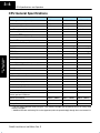
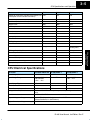
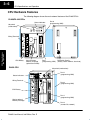
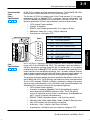
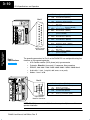
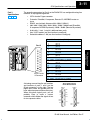
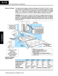
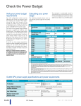
3–4 CPU Specifications and Operation CPU General Specifications Features DL430 DL440 DL450 Total Program memory (words) 6.5K 14.5K / 22.5K* 22.8K / 30.8K* Ladder memory (words), built-in 3.5K 7.5K / 15.5K* 7.5K / 15.5K* V-memory (words) 3.0K 7.0K 15.3K Scan Time, typical (1 K boolean) 8 – 10 mS 2 – 3 mS 4 – 5 mS Run time edit No Yes Yes Programming Yes Yes Yes Handheld programmer with cassette tape interface Yes Yes Yes DirectSOFT32 programming for Windows Yes Yes Yes Built-in communication ports 2 ports 2 ports 4 ports CMOS RAM No w/mem. cartridge w/mem. cartridge UVPROM No w/mem. cartridge w/mem. cartridge EEPROM Standard on CPU w/mem. cartridge w/mem. cartridge FLASH RAM No No Standard on CPU CoProcessor modules Yes Yes Yes Networking modules Yes Yes Yes RS232C/RS422 Data Comm. Module Yes Yes Yes 1152 1664 3584 Local I/O / Local expansion I/O / Remote I/O 640 640 4096 Remote I/O 512 max. 1024 max. 2048 max. Remote I/O Channels 2 2 3 Local discrete input points maximum 320 320 1024 Local discrete output points maximum 320 320 1024 Local analog input channels maximum 320** 320** 512** Local analog output channels maximum 320** 320** 512** Maximum number of channels / masters (remote or slice) per local CPU base 2 2 2 Remote I/O Distance 3300 ft. (1000m) 3300 ft. (1000m) 3300 ft. (1000m) Discrete I/O Module Point Density 8/16/32/64 8/16/32/64 8/16/32/64 Slots per Base 4/6/8 4/6/8 4/6/8 CPU Specifications and Operation RLL and RLL PLUS Compatible with: Total I/O Total I/O available as: * The first values represent CPUs using the 7.5K memory cartridge and the second value is for using 15.5K memory cartridges. ** Additional Discrete and Analog I/O can be supported (within the power budget) through the use of remote I/O. DL405 User Manual, 3rd Edition, Rev. E CPU Specifications and Operation DL430 DL440 DL450 Number of instructions available (see Chapter 5 for a description of the available instructions) 113 170 210 Control relays 480 1024 2048 Special relays (system defined) 288 352 512 384 1024 1024 V-memory 3072 words 7168 words 15360 words Timers 128 256 256 Counters 128 128 256 Immediate I/O Yes Yes Yes Interrupt input 8 points 16 points 16 points Subroutines No Yes Yes For/Next Loops No Yes Yes Drum Timers No No Yes Math Integer Integer Integer and Floating Point PID Loop Control, built-in No No 16 loops Time of Day Clock/Calendar No Yes Yes Internal diagnostics Yes Yes Yes Password security No Yes Yes, multi-level System and user error log No Yes Yes Battery backup Yes Yes Yes Stages in RLL PLUS CPU Electrical Specifications Parameter DL430/DL440/DL450 DL440/450DC–1 DL440/450DC–2 Input Voltage, Nominal 120 VAC 24 VDC 125 VDC Input Voltage Range 100–120 VAC and 196–240 VAC +10% –15% 20–29 VDC 100–132 VDC +10% –15% Input Voltage Ripple N/A less than 10% less than 10% Inrush Current, maximum 20 A 10 A 20 A Power Consumption, maximum 50 VA 38W 30 W Voltage withstand (dielectric strength) 1 min. at 1500 VAC between primary, secondary, field ground and run relay Insulation resistance > 10MW at 500 VDC Output Voltage, auxiliary power supply 20–28 VDC (24 nominal), ripple more than 1V P-P (N/A on DL440–DC–1 and DL440–2) Output Current, auxiliary power supply 24 VDC @ 400 mA maximum DL405 User Manual, 3rd Edition, Rev. E CPU Specifications and Operation Feature 3–5 3–6 CPU Specifications and Operation CPU Hardware Features The following diagram shows the main external features of the DL405 CPUs. DL430/DL440 CPUs Status indicators Keyswitch (mode select) Port 0 (programming, MMI) CPU Specifications and Operation Wiring Terminals CPU Battery Slot for DL440 Memory Cartridge (optional on DL450) DL450 CPU Status indicators Wiring Terminals Port 1 (programming, MMI) DIP Switch Config. (battery, station address, baud rate) Keyswitch (mode select) Port 2 (programming, MMI) Port 0 (programming, MMI) CPU Battery Port 1 (programming, MMI) Slot for optional Memory Cartridge Port 3 (remote I/O, network) DL405 User Manual, 3rd Edition, Rev. E CPU Specifications and Operation Communication Ports Port 0 Specifications 430 440 450 3–9 DL405 CPUs provides up to four communication ports. The DL430/DL440 CPUs have two ports, while the DL450 CPU has a total of four ports. The first port (all CPUs) is located on the 15 pin D-shell conector. It is for general programming such as DirectSOFT32, or operator interface connections. The D4–HPP handheld programmer can only be used on this port on the CPU. The operating parameters for Port 0 are permanently set to the values shown. S 15 Pin female D type connector S Protocol: K sequence S RS232C, non-isolated, distance within 15 m (approx. 50 feet) S 9600 baud, 8 data bits, 1 start, 1 stop bit, odd parity S Asynchronous, Half duplex, DTE Port 0 Pin Descriptions (All CPUs) Port 0 9 8 15 15-pin Female D Connector Port 1 Specifications 430 440 450 Port 1 (all CPUs) is located on the 25-pin connector, and is called the “secondary comm port” for the DL430/DL440 CPUs. The secondary comm port address is stored in the memory cartridge along with the I/O configuration. It is for general programming such as DirectSOFT32, operator interfaces, and networking, but it cannot connect to the handheld programmer. Port 1 provides additional features such as programmable baud rate, parity, ASCII/Hex mode and network address. Its RS422 signals support multidrop networking and programming applications. The baud rate and station address override is selected by dip switches on the rear of the DL430/DL440 CPUs. The DL450 uses Aux functions to set the same parameters (it has no DIP switches). RS232C or RS422 is selected by cabling to the proper signal pin sets on the connector. Parity, ASCII/Hex mode and station address are selected by AUX (auxiliary) functions with a programming device. S 25 Pin female D type connector S Protocols: K-sequence, DirectNet. The DL450 additionally supports Non-Sequence and MODBUS protocols. (Note: The DL430 cannot support K–sequence on ports 0 and 1 simultaneously. Use DirectNet on port 1 if port 0 is used for communications). S RS232C / RS422, Selectable address 1–90 (use Aux function) S 300/ 600/ 1200 / 2400 / 4800 / 9600 / 19200 / (38400 DL450 only) baud S Hex / ASCII modes (use Aux function to configure) S 8 data bits, 1 start, 1 stop bit, Odd, Even or No parity S Asynchronous, Half duplex (use Aux function to configure), DTE DL405 User Manual, 3rd Edition, Rev. E CPU Specifications and Operation 1 1 YOP Sense connection between HPP and CPU 2 TXD Transmit Data (RS232C) 3 RXD Receive Data (RS232C) 4 ONLINE Request Communication (TTL) 5 ABNO CPU Error (TTL) 6 PRDY CPU ready to communicate (TTL) 7 CTS Clear to Send (RS232C) 8 YOM Sense connection between HPP and CPU 9 – Not Used 10 LCBL Sense cable connection (TTL) 11 5V2 5 VDC for HPP logic 12 5V2 5 VDC for LCD backlight 13 0V Logic ground 14 0V Logic ground 15 0V Logic ground 3–10 CPU Specifications and Operation Port 1 Pin Descriptions (All CPUs) Port 1 1 14 13 25 CPU Specifications and Operation 25-pin Female D Connector Port 2 Specifications 430 440 450 1 2 3 4 5 6 7 8 9 10 11 12 13 14 15 16 17 18 19 20 21 22 23 24 25 – TXD RXD RTS CTS – SG – RXD+ RXD– CTS+ – – TXD+ – TXD– – RTS– RTS+ – – – CTS– – – Not used Transmit Data (RS232C) Receive Data (RS232C) Request to Send (RS232C) Clear to Send (RS2332C) Not used Signal ground (RS232C/RS422) (port 3 on DL450) Receive Data + (RS422) Receive Data – (RS422) Clear to Send + (RS422) (port 3 on DL450) (port 3 on DL450) Transmit Data + (RS422) Not used Transmit Data – (RS422) Not used Request to Send – (RS422) Request to Send + (RS422) Not used Not used Not used Clear to Send – (RS422) (port 3 on DL450) (port 3 on DL450) The operating parameters for Port 2 on the DL450 CPU are configurable using Aux functions on a programming device. S 6 Pin female modular (RJ12 phone jack) type connector S Protocols: DirectNet (slave only), K sequence, Non-procedure S RS232C, 300 / 600 / 1200 / 2400 / 4800 / 9600 / 19200 / 38400 baud S 8 data bits, 1 start, 1 stop bit; odd, even, or no parity S Nodes – from 1 to 90 Port 2 Port 2 Pin Descriptions (DL450) 1 6 1 2 3 4 5 6 0V 5V RXD TXD 5V 0V Power (–) connection (GND) Power (+) conection Receive Data (RS232C) Transmit Data (RS232C Power (+) conection Power (–) connection (GND) 6-pin Female Modular Connector NOTE: The 5V pins are rated at 200mA maximum, primarilly for use with some operator interfaces. DL405 User Manual, 3rd Edition, Rev. E CPU Specifications and Operation Port 3 Specifications 430 440 450 3–11 The operating parameters for Port 3 on the DL450 CPU are configurable using Aux functions on a programming device. S S S S S S S 25 Pin female D type connector Protocols: DirectNet, K-sequence, Remote I/O, MODBUS master or slave RS422, non-isolated, distance within 1000 ft (3280 ft.) 300 / 600 / 1200 /2400 / 4800 / 9600 / 19200 / 38400 baud (DirectNet, K-sequence, MODBUS protocols),19200 / 38400 (Remote I/0 protocol) 8 data bits, 1 start, 1 stop bit, odd/none/even parity Hex / ASCII modes (use Aux function to configure) Selectable address 1–90 (use Aux function to configure) Port 3 Pin Descriptions (DL450) Port 3 1 25 25-pin Female D Connector – – SG TXD+ TXD– – – – – – RXD+ RXD– A drawing summarizing the pin locations and functions of ports 1 and 3 on the 25-pin connector is to the right. The two logical ports share two ground pins, but have separate communications data pins. When using both logical ports, you will probably have to make a custom connector which divides the signals in two for two separate cables. Not used (port 1) (port 1) (port 1) (port 1) Not used Signal ground Not used (port 1) (port 1) (port 1) Transmit Data (+), (RS422) Transmit Data (–), (RS422) (port 1) Not used (port 1) Not used (port 1) (port 1) Not used Not used Not used (port 1) Receive Data (+), (RS422) Receive Data (–), (RS422) CPU Specifications and Operation 13 14 1 2 3 4 5 6 7 8 9 10 11 12 13 14 15 16 17 18 19 20 21 22 23 24 25 Two Logical Ports on the 25 Pin Connector Port 3 Port 1 TXD RXD RTS CTS 0V RXD+ RXD– CTS+ TXD+ TXD– RTS– RTS+ 0V CTS– TXD+ TXD– RXD+ RXD– DL405 User Manual, 3rd Edition, Rev. E 8–2 PID Loop Operation (DL450 only) DL450 PID Loop Features Main Features The DL450 process loop control offers a sophisticated set of features to address many application needs. The main features are: S S S S S S Up to 16 loops, individual programmable sample rates Manual/ Automatic/Cascaded loop capability available Two types of bumpless transfer available Full-featured alarms Ramp/soak generator with up to 16 segments Auto Tuning Maintenance and Troubleshooting PID Loop Operation (DL450 Only) NOTE: The D4–450 CPU’s PID algorithm now supports the use of 16-bit analog inputs and outputs, auto tuning and other advanced features. This CPU requires DirectSOFT32 Version 3.0c Build 58 (or later) and CPU firmware version 1.9 (H8) and 2.446 (SH) (or later) to implement those features. See our website for more information: www.automationdirect.com. The DL450 CPU has process control loop capability in addition to ladder program execution. You can select and configure up to sixteen loops. All sensor and actuator wiring connects to standard DL405 I/O modules, as shown below. All process variables, gain values, alarm levels, etc., associated with each loop reside in a Loop Variable Table in the CPU. The DL450 CPU reads process variable (PV) inputs during each scan. Then it makes PID loop calculations during a dedicated time slice on each PLC scan, updating the control output value. The control loops use the Proportional-Integral-Derivative (PID) algorithm to generate the control output command. This chapter describes how the loops operate,and what you must do to configure and tune the loops. Analog or Digital Output DL450 CPU PID Loop Calculations Manufacturing Process Analog Input The best tool for configuring loops in the DL450 is the DirectSOFT32 programming software, Release 2.0 or later. DirectSOFT32 uses dialog boxes to create a forms-like editor to let you individually set up the loops. After completing the setup, you can use DirectSOFT32’s PID Trend View to tune each loop. The configuration and tuning selections you make are stored in the DL450’s FLASH memory, which is retentive. The loop parameters also may be saved to disk for recall later. DL405 User Manual, 3rd Edition, Rev. E 8–3 PID Loop Operation (DL450 only) Number of loops Selectable, 16 maximum CPU V-memory needed 32 words (V locations) per loop selected, 64 words if using ramp/soak PID algorithm Position or Velocity form of the PID equation Control Output polarity Selectable direct-acting or reverse-acting Error term curves Selectable as linear, square root of error, and error squared Loop update rate (time between PID calculation) 0.05 to 99.99 seconds, user programmable Minimum loop update rate 0.05 seconds for 1 to 4 loops, 0.1 seconds for 5 to 8 loops , and 0.2 seconds for 9 to 16 loops Loop modes Automatic, Manual (operator control), or Cascade control Ramp/Soak Generator Up to 8 ramp/soak steps (16 segments) per loop with indication of ramp/soak step number PV curves Select standard linear, or square-root extract (for flow meter input) Set Point Limits Specify minimum and maximum setpoint values Process Variable Limits Specify minimum and maximum Process Variable values Proportional Gain Specify gains of 0.0 to 99.99 Integrator (Reset) Specify reset time of 0.0 to 99.99 in units of seconds or minutes Derivative (Rate) Specify the derivative time from 0.00 to 99.99 seconds Rate Limits Specify derivative gain limiting from 1 to 20 Bumpless Transfer I Automatically initialized bias and setpoint when control switches from manual to automatic Bumpless Transfer II Automatically set the bias equal to the control output when control switches from manual to automatic Step Bias Provides proportional bias adjustment for large setpoint changes Anti-windup For position form of PID, this inhibits integrator action when the control output reaches 0% or 100 % (speeds up loop recovery when output recovers from saturation) Error Deadband Specify a tolerance (plus and minus) for the error term (SP–PV), so that no change in control output value is made Alarm Feature Specifications Deadband Specify 0.1% to 5% alarm deadband on all alarms PV Alarm Points Select PV alarm settings for Low–low, Low, High, and High-high conditions PV Deviation Specify alarms for two ranges of PV deviation from the setpoint value Rate of Change Detect when PV exceeds a rate of change limit you specify DL405 User Manual, 3rd Edition, Rev. E Maintenance Specifications PID Loop Operation (DL450 Only) PID Loop Feature


![[U7.03.41] Procédure MACR_ECREVISSE](http://vs1.manualzilla.com/store/data/006357801_1-c0143633884180ca091f10f4d65de8cd-150x150.png)