1
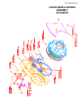
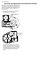
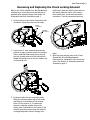
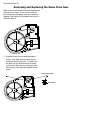
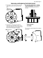
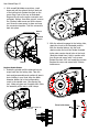
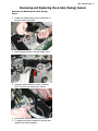
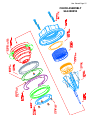
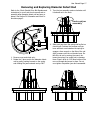
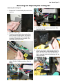
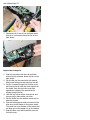
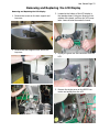
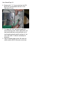
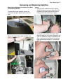
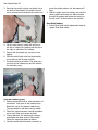
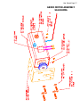
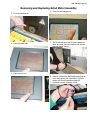
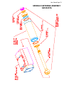
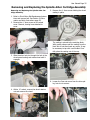
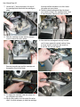
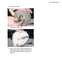
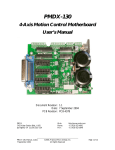
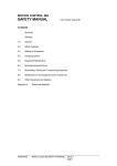
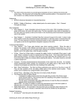
User Manual Page 1
SERVICE PARTS REPLACEMENT
SCHEMATICS & WORK INSTRUCTIONS
USER SECTION
CHUCK SWING CASTING ASSEMBLY EXPLODED VIEW: SA12500CA............... PAGE 3
CHUCK SPINDLE DRIVE BELT REPLACEMENT ......................................... PAGE 5
REMOVE/REPLACE CHUCK BELT IDLER ASSEMBLY.................................. PAGE 8
REMOVE/REPLACE CHUCK LOCKING SOLENOID ..................................... PAGE 9
REMOVE/REPLACE NEMA DRIVE GEAR................................................. PAGE 10
REMOVE/REPLACE ROTATE SENSOR ................................................... PAGE 10
REMOVE/REPLACE A-AXIS (SWING) SENSOR........................................ PAGE 13
CHUCK ASSEMBLY EXPLODED VIEW: SA12505TA ...................................... PAGE 15
REMOVE/REPLACE DIAMETER DETECT ROD ........................................ PAGE 17
ELECTRICAL WIRING DIAGRAM: PP12150EF ................................................... PAGE 19
REMOVE/REPLACE COOLING FAN ........................................................ PAGE 21
REMOVE/REPLACE LCD DISPLAY ......................................................... PAGE 23
REMOVE/REPLACE SWITCHES E-STOP,CYCLE START & FEED HOLD .............. PAGE 25
GRIND MOTOR ASSEMBLY EXPLODED VIEW: SA12640MA .......................... PAGE 27
REMOVE/REPLACE GRIND MOTOR ASSEMBLY ...................................... PAGE 29
REMOVE/REPLACE GRIND MOTOR BELT .............................................. PAGE 31
REMOVE/REPLACE GRIND MOTOR BRUSHES........................................ PAGE 32
SPINDLE CARTRIDGE ASSEMBLY EXPLODED VIEW: SA12615TA.................. PAGE 33
REMOVE/REPLACE SPINDLE ARBOR CARTRIDGE ASSEMBLY.................. PAGE 35
User Manual Page 2
User Manual Page 3
CHUCK SWING CASTING
ASSEMBLY
SA12500CA
User Manual Page 4
User Manual Page 5
Removing and Replacing the Chuck Spindle Drive Belt
1. Remove the 3, 3mm button head screws with
a 2mm Allen wrench and remove the cover
3MM button
head screws
plate.
2. Remove the 4, 4mm cap screws from the
chuck knob with a 3mm Allen wrench. Lift the
chuck knob straight up. The jaw assembly and
knob will come out together. Set aside.
4MM cap screws
3. Do not remove the jaws or springs
from the assembly. They are ground in
position for accuracy and are not to be
removed.
Knob and jaw
assembly
Now rotate the crescent shaped knob retainers
and remove.
cover
Knob retainers
User Manual Page 6
4. To loosen and remove belt, insert a flat blade
screw driver in the slotted bearing screw.
Loosen
6. Replace the belt. Using two fingers on a flat
blade screw driver, rotate slotted bearing
screw clockwise until belt just pulls to a flat
condition. There will be a noticeable increase
in resistance past this point of rotation.
Continue rotating another 1/16". Hold screw
driver in this position and secure bearing lock
screw.
Tighten
5. On the back of the casting is a 4 mm button
head screw that locks the bearing in place.
Loosen with a 2.5mm Allen wrench. Rotate the
bearing screw counterclockwise and loosen
the belt. Slip the belt off the sprockets and
remove.
4MM locking screw
User Manual Page 7
Replace Chuck Spindle Drive Belt
1. Take the knob and jaw assembly and position
all jaws in slots. Holding in your hand, align
the black diameter detect rod in the
corresponding notch in the spindle cone. (See
drawing below). Make sure jaws are in spindle
slots. Slide the assembly all the way in until it
3. With the beveled side up, slip the knob
retainer under the knob and locate threaded
holes under counter bored holes in the knob.
(Note the dotted lines). Hold in position with
Bevel side down
Diameter detect rod
Notch
stops.
2. With the solenoid engaged in the locking
hole, rotate the chuck to the illustrated
position.
Top
your finger and secure with 2 cap screws.
Rotate the chuck 180° and repeat the
process. Replace the cover and secure with
3 button head screws.
User Manual Page 8
Removing and Replacing the Chuck Belt Idler Assembly
Refer to the Chuck Spindle Drive Belt Replacement
instructions for cover and chuck removal, belt adjustment and reassembly after replacement of belt
idler. See Section 24 Schematics and Work Instructions page 3.
1. Remove the 4mm locking screw and lift the
idler assembly out of the housing.
4MM locking screw
Idler assembly
To install the idler, position over screw hole
outside of belt and thread screw into idler just
until snug. Adjust belt per the Chuck Spindle
Drive Belt Replacement instructions. See Section 24 Schematics and Work Instructions
page 3.
User Manual Page 9
Removing and Replacing the Chuck Locking Solenoid
Refer to the Chuck Spindle Drive Belt Replacement
instructions for cover and chuck removal and reassembly after solenoid change. See Section 24
Schematics and Work Instructions page 3.
Hold the pin back and tuck it under and into
the locking hole and seat it in the recess.
Secure with the 2 screws and connect the
connectors. Tuck the connectors back into
1. Remove the cover and chuck. Disconnect both
connectors. Place the wires out of the way.
Sensor
connectors
Solenoid
connectors
Solenoid
assembly
2. Unscrew the 2, 4mm screws that secure the
solenoid in place from the back of the housing.
Take a small flat blade screw driver and pull
the lock pin back and out of the locking hole.
Rotate the spindle cone so the pin remains out
of the locking hole.
3. Continue holding the pin back while gently
lifting the solenoid upward out of the recess
and tilting it to the bottom of the housing.
Once it is free remove it. To replace the
solenoid, rotate the spindle cone so the
locking hole is visible and in the center of the
solenoid mounting recess. Keep the solenoid
in straight alignment with the locking hole.
place.
4. With the wires secured refer to the Chuck
Spindle Belt Drive Belt Replacement
instructions for reassembly of the chuck and
cover. See Section 24 Schematics and Work
Instructions page 3.
User Manual Page 10
Removing and Replacing the Nema Drive Gear
Refer to the Chuck Spindle Drive Belt Replacement
instructions for cover, chuck and belt removal
and reassembly after Nema drive gear has been
replaced. See Section 24 Schematics and Work Instructions page 3.
1. Rotate until set screw is easily accessible.
Using a 1/16 Allen wrench loosen the set
screw and remove the gear. To replace slip
the gear over the shaft with the set screw
over the flat. Bring the top of the gear flush
with the top of the shaft and tighten the set
screw.
Nema drive gear
Set screw
User Manual Page 11
Removing and Replacing the Rotate Sensor
1. Remove the 3, 3mm button head screws with
a 2mm Allen wrench and remove the cover
plate.
3MM button
head screws
2. Remove the 4, 4mm cap screws from the
chuck knob with a 3mm Allen wrench. Lift the
chuck knob straight up. The jaw assembly and
knob will come out together. Set aside.
4MM cap screws
3. Do not remove the jaws or springs
from the assembly. They are ground in
position for accuracy and are not to be
removed.
Knob and jaw
assembly
Now rotate the crescent shaped knob retainers
and remove.
cover
Knob retainers
User Manual Page 12
4. With a small flat blade screw driver, reach
down and pull the solenoid lock pin back out
of the locking hole. Rotate the chuck so the
sensor flag is out of the way as illustrated.
Depress the clip on the sensor connector and
pull apart. Using a 2mm Allen wrench, remove
the 2 button head screws and lift the sensor
out. Screw the new sensor in place and snap
the connectors together. Tuck the connectors
back into place.
Sensor
flag
Solenoid
lock pin
2. With the solenoid engaged in the locking hole,
rotate the chuck to the illustrated position.
With the beveled side up, slip the knob
retainer under the knob and locate threaded
holes under counter bored holes in the knob.
(Note the dotted lines). Hold in position with
your finger and secure with 2 cap screws.
Rotate the chuck 180° and repeat the process.
Replace the cover and secure with 3 button
head screws.
Rotate
Sensor
Replace Rotate Sensor
1. Rotate the spindle until the solenoid lock pin
snaps back into the locking hole. Take the
knob and jaw assembly and position all jaws in
slots. Holding in your hand, align the black
diameter detect rod in the corresponding
notch in the spindle cone. (See drawing below). Make sure jaws are in spindle slots. Slide
the assembly all the way in until it stops.
Bevel side down
Diameter detect rod
Notch
Top
User Manual Page 13
Removing and Replacing the A-Axis (Swing) Sensor
Removing and Replacing the A-Axis (Swing)
Sensor
1. Locate the marked swing sensor cable and unplug the sensor connector.
2. Note the access hole in the dust shield cover.
3. Swing the dust shield up or down to access
the 2, 2mm screws securing the sensor.
4. Unscrew the screws and remove the sensor.
5. To replace the sensor reverse the process and
snap the connector together.
User Manual Page 14
User Manual Page 15
CHUCK ASSEMBLY
SA12505TA
User Manual Page 16
User Manual Page 17
Removing and Replacing Diameter Detect Rod
Refer to the Chuck Spindle Drive Belt Replacement
instructions for cover and chuck removal and reassembly after diameter detect rod has been replaced. See Section 24 Schematics and Work Instructions page 3.
3. Turn the jaw assembly counter clockwise until
it bottoms out in the knob.
Knob and jaw
assembly
1. Remove cover and chuck only.
2. Rotate the 2 jaws next to the diameter detect
rod by gently pushing forward on the spring
and rotating the jaws outward and up 180°.
4. Slide each jaw down the spring and lay flat on
chuck knob. Continue this process until you
have sufficient room between the springs to
engage a 4mm wrench on the flats of the rod.
Apply pressure until the rod breaks loose. Rotate the rod out by moving the wrench between the springs, be careful not to damage
them. Place a drop of #243 blue loctite on the
new rod threads and screw in place. Do not
over tighten. Reposition jaws and reassemble.
User Manual Page 18
User Manual Page 19
ELECTRICAL WIRING DIAGRAM
SA12150EF
User Manual Page 20
User Manual Page 21
Removing and Replacing the Cooling Fan
Removing the Cooling Fan
1. Remove the 2 screws holding the panel to the
machine.
5. On the front of the panel, snap the fan filter
cover from the fan.
2. Swing the panel open.
3. There are red and black wires coming from
the fan and a white and green wire coming
from the power switch. They merge into a
connector. Disconnect the connector. The
panel will swing open further.
6. Using a nut driver to hold the nuts inside the
panel, remove the 4 screws holding the fan in
place. The front cover comes off and the fan
can be removed from the inside along with the
aluminum baffle.
4. Note the white and green wires that go to the
switch. Pull the 2 blade connectors from the
switch.
User Manual Page 22
7. Disconnect the 2 sets of red and black wires
that go to a connector above the fan on the
back board.
Replace the Cooling Fan
1. Snap the connector with the red and black
wires into the connector above the fan on the
back board.
2. Slip the fan into the panel with the red and
black wires facing you and exiting to the left.
3. Put the 4 screws through the front fan cover
and line up the fan with the screw holes from
the inside. Push the front fan cover flush
against the outside of the panel and the
screws through the fan.
4. Hold the top screws with a screw driver and
secure nuts in place with a nut driver.
5. Slip the baffle over the bottom screws and repeat the process.
6. Connect the large and small connectors of the
blue wires to the blades on the power switch.
The small one is on the back of the switch and
the large one is the angled one on the bottom.
7. Snap the filter cover and foam filter over the
front fan cover.
User Manual Page 23
Removing and Replacing the LCD Display
Removing and Replacing the LCD Display
1. Remove the screws on the door support and
top cover.
2. Remove the door support cover and lift the
top cover.
3. Located at the bottom of the LCD display is
the interface board. Using two fingers on the
outside of the board, pull from the LCD receptacle. Leave all wires connected to board.
4. Unplug the green five wire connector from the
LCD.
5. Remove the single screw on the RS232 connector and unplug from the LCD.
User Manual Page 24
6. Remove the 7, ¼” acorn nuts from the LCD.
Note: One is inaccessible and has no nut.
Slide the LCD out.
1. To replace the LCD, slip back through the
front of the top cover. Hold in place with your
hand and install acorn nuts just until one to
two threads protrude past the surface of the
nut. A thin wall ¼” socket is necessary for
clearance.
2. Plug in interface board, green five wire connector and the RS232 connector and screw.
User Manual Page 25
Removing and Replacing Switches
Removing and Replacing The E-Stop, Cycle Start
and Feed Hold Switches
To remove the power switches, remove the
screws from the door support casting and top
cover.
Remove the support door casting and tilt it up.
.
E-Stop
1. Using a pair of needle nose pliers, hold the
switch block down with your thumb. Grab the
connectors and gently pull up while using a
rocking motion and remove the 2 wires.
2. Connected to the switch is the switch block.
Note the small key in the center left and to the
right is a release clip. With a small blade screw
driver reach down on the side of the clip and
press inward while pulling up. The block will
slide off.
User Manual Page 26
3. Securing the switch in place is a plastic nut at
the base of the threads. Use needle nose pliers to remove the nut and slide the switch out.
move the plastic retainer nut, also same as EStop.
5. Slide the switch from the casting, but note the
rubber gasket and locator pin that protrudes
through the gasket and locates the switch on
the top cover. It must locate in this position.
Feed Hold (amber)
1. Follow Cycle Start switch replacement steps to
replace Feed Hold switch.
4. Slip the new switch in place with the key to
the left or inside of the casting and the clip to
the right or wall side of the casting.
5. Secure with the plastic nut, but do not over
tighten.
6. Slide the switch block over the keyed switch,
prong side up until it snaps in place.
7. Connect the wires as follows. The green wire
connects to the inside prong and the white to
the wall side prong.
Cycle Start switch (green)
1. Before removing the wires, note the pattern of
connection. Two green to top inside prongs.
Black then red on the bottom inside prong.
The top outside or wall side prong is vacant.
2. Follow the same connector removal procedure
as for the E-Stop and remove all wires.
3. Though different, the switch block removes
and installs the same as the E-Stop switch.
Follow the same instructions as above.
4. Once the switch block has been removed, re-
User Manual Page 27
GRIND MOTOR ASSEMBLY
SA12640MA
User Manual Page 28
User Manual Page 29
Removing and Replacing Grind Motor Assembly
1. Turn the machine on.
2. Push the check icon.
4. Push the belt change icon.
5. The X-Axis will move into the belt change position and stop. Shut the machine off and disconnect power source.
3. Push the tool icon.
6. Refer to Grind Motor Belt Replacement instructions and remove belt. See Section 24 Schematics and Work Instructions page 29.
7. Unplug the motor connector wires.
User Manual Page 30
8. Remove the 4 screws and washers holding the
motor in place.
9. Slide the motor down the slotted bracket and
out of the machine. Remove the cooling hose
connected to the motor.
10. To replace the motor assembly, the machine
must in the belt change position.
11. Reconnect the cooling hose and slip the motor
shaft with the pulley in place up the slotted
bracket and aligned with slots and screw hole.
12. Install screws and washers just until they
bring surfaces together.
13. Reconnect motor wires and zip tie if needed.
14. Refer to Grind Motor Belt Replacement instructions for belt replacement and proper belt tension. See Section 24 Schematics and Work Instructions page 29.
User Manual Page 31
Removing and Replacing Grind Motor Belt
1.
2.
3.
4.
5.
6.
7.
8.
9.
Turn the machine on and push check.
Push the tool icon.
Push the belt icon in upper right hand corner.
The X-Axis moves to the center and stops.
Turn the machine off and unplug from power
source.
Remove the belt access panel at back of machine.
Loosen the 4 mounting bolts and swing the
motor up to loosen the belt.
Tighten one bolt and remove the belt.
Install the new belt and loosen the bolt. Place
your finger tip on the rear of the motor to
keep it level. Let the weight of the motor
swing down and tension the belt. This will apply the proper tension without stressing the
motor or spindle bearings. Tighten the bolts
evenly and replace the access panel.
Tighten
Loosen
User Manual Page 32
Removing and Replacing Grind Motor Brushes
1. Refer to Removing and Replacing Grind Motor
Assembly instructions to remove and replace
the motor. See Section 24 Schematics and
Work Instructions page 27.
2. Once the motor is removed, note the slotted
brush retaining screws on each side of the
motor.
3. Unscrew and check brushes one at a time noting how they were oriented in the guide.
Marking them is a good idea.
4. Check each brush for damage to the springs
or for excessive wear. They should measure
no less than .275 from the lowest point of the
radius to the top of the brush.
5. If either one needs replacement you must replace both brushes with new ones. If not,
carefully replace them the same way they
came out.
6. If you are replacing with new brushes, be sure
to install them with the radius of the brush in
line with the rotation of the motor.
7. After brushes are installed, refer to Removing
and Replacing Grind Motor Assembly instruc-
tions to replace the motor. See Section 24
Schematics and Work Instructions page 27.
User Manual Page 33
SPINDLE CARTRIDGE ASSEMBLY
SA12615TA
User Manual Page 34
User Manual Page 35
Removing and Replacing the Spindle Arbor Cartridge Assembly
Removing and Replacing the Spindle Arbor Cartridge Assembly.
5. Remove the 4, 4mm screws holding the wheel
casting in place.
1. Refer to Grind Motor Belt Replacement instructions and remove belt. See Section 24 Schematics and Work Instructions page 29.
2. Remove the 4, 3mm screws on the wheel
cover. Remove, leaving hose attached to
cover.
The casting is pinned to the cartridge block.
With gentle pressure pull the casting from the
block but do not disconnect any wires. It may
be necessary to tap with a soft mallet. Carefully place the casting out of the way.
3. Slide the arbor lock pin through the hole in the
wheel guard casting and rotate wheel until it
engages.
6. Loosen the 3mm set screw from the drive pulley, but do not remove.
4. With a ½” socket, remove the wheel retainer
nut and remove the wheel.
User Manual Page 36
7. Loosen the 2, 3mm set screws in the top of
the cartridge block that holds the cartridge in
place.
forward to allow clearance to do this. Leave
the pulley set screw loose.
11. Take the wheel casting and align the dowel
pins with the holes in the cartridge block. Push
or tap into place. Secure with 4mm screws.
8. Slide the cartridge forward allowing enough
room to remove the drive pulley.
12. Now slide the cartridge all the way forward
until it stops against the wheel casting. Using
a torque wrench, torque the set screws to
6 inch lbs. Do not over tighten.
Remove the pulley and pull the cartridge out
through the front of the block.
9. To replace the cartridge, slide into block, but
do not tighten set screws.
10. Slip the drive pulley over the end of the arbor
shaft. It will be necessary to slide the cartridge
User Manual Page 37
1. Reinstall the wheel.
2. Reinstall the wheel cover.
3. Refer to Grind Motor Belt Replacement to install and set proper tension on belt. See Section 24 Schematics and Work Instructions
page 29.