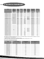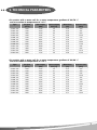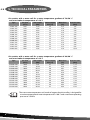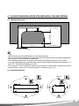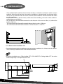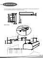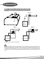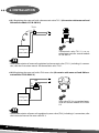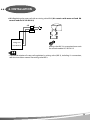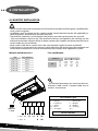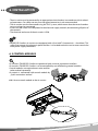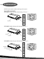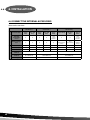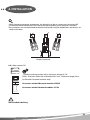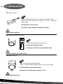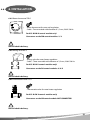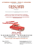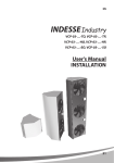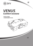
1
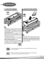
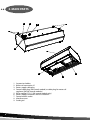
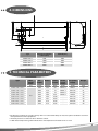
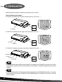
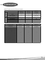
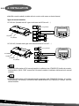
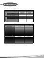
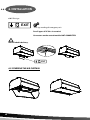
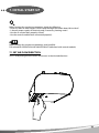
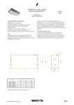
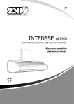
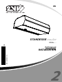
EN
STANDESSE Comfort
1/1
VCS4X-….
Full manual
B01-0208-0511-15
INSTALLATION
2
1. BEFORE YOU BEGIN
Meaning of symbols in the manual:
SYMBOL
MEANING
ATTENTION!
Warning/caution
DO NOT OVERLOOK!
Important instructions
YOU WILL NEED
NOTE
Practical tips and information
TECHNICAL INFORMATION
More detailed technical information
LINK
Refer to other parts/sections
of the manual
Before installation, thoroughly read the section “Safe use of air curtains”. It con¬tains all instructions on the safe and correct use of the product.
This manual contains important instructions to ensure correct installation of the air curtain. Before installation, read all of the following instructions thoroughly and then adhere to them! The
manufacturer reserves the right to make changes, including to technical documentation without
prior notice. Save this user manual for further use. The instructions in this manual are a part of
the product.
Declaration of conformity
Declatarion of confortmity for air curtains STANDESSE Comfort is located at www.2vv.cz
2
2. UNPACKING
2.1 CHECK THE SHIPMENT
2.2 UNPACK THE AIR CURTAIN
• After delivery, immediately check to see if the
packaged product is damaged. If the packaging is damaged contact the delivery service. If
the complaint is not filed in time, your claim
may not be valid later.
• Check to see if it is the same product you ordered. If there are any discrepancies, do not
unpack the curtain, and immediately report
the defect to the supplier.
• If the curtain has been transported at temper• After unpacking, check to see if the curtain
atures below 0° C, it will be necessary to let it
and other parts are in order. If you have any
sit for at least 2 hours under normal operating
doubts, contact the supplier.
conditions after unpacking, without turning it
• Never install a damaged air curtain!
on. This will allow the air curtain‘s interior tem• If you do not unpack the curtain immediately
perature to stabilise.
after delivery, it must be stored in a dry indoor
environment with an ambient temperature between +5 °C and +35 °C
+35°C
+5°C
All used packaging materials are environmentally friendly and may be
reused or recycled.
Take an active part in environmental protection and see that packaging
materials are correctly disposed of or repurposed.
3
3. MAIN PARTS
3
4
1
5
1
2
8
9
6
7
1.
2.
3.
4.
5.
6.
7.
8.
9.
4
Suspension holders
Water coil connection ¾“
Power supply cable plug
Control cable plug (SM control module) or cable plug for water coil
regulator (DA,DM control modules)
Pit for capillary TV1/1 (SM control module only)
Power supply connectors and fusse location
Control modul socket
Inlet face cover
Outlet grid
4. DIMENSIONS
334
131
312
418
45
57
114
556
250
40
38
52
334
A
B
Type
Spacing of installation
Width B [mm]
holes A [mm]
VCS4x-10x-x..
VCS4x-15x-x..
VCS4x-20x-x..
VCS4x-25x-x..
994
1494
1994
2394
1054
1554
2054
2454
5. TECHNICAL PARAMETERS
Type
Max.
height
doors
Air
output
Noise**
Heater
output
[m]
Heater
power
supply
Fan power
supply
Weight
[kg]
[m3/h]
[dB(A)]
[kW]
[V/A]
[V/A]
VCS4A-10E-1-0-0-2
1950
45,5
9,5
400/13,7
230/1,1
43
VCS4A-15E-1-0-0-2
2850
47,5
15
400/21,7
230/1,75
61
VCS4A-20E-1-0-0-2
3700
48,3
19
400/27,5
230/2,35
78
VCS4A-25E-1-0-0-2
4500
48,9
24,5
400/35,4
230/3,0
96
VCS4A-10V-1-0-0-2
5,0
1850
45,5
15,48
-
230/1,10
45
VCS4A-15V-1-0-0-2
2750
49,7
33,43
-
230/1,75
63
VCS4A-20V-1-0-0-2
3600
51,0
45,39
-
230/2,35
78
VCS4A-25V-1-0-0-2
4400
51,5
57,24
-
230/3,00
98
*The distance at which the average velocity of the air current flow drops to 2m/s.For optimal conditions and maximum performance of the equipment.
** Acoustic pressure at a distance of 3 m from the curtain.
*** With water temperature gradient of 90º/70° C and temperature of suctioned air at +18°C
5
5. TECHNICAL PARAMETERS
Type
Max.
height
doors
Air
output
Noise**
Heater
output
Heater
power
supply
[m]
Fan power
supply
Weight
[m3/h]
[dB(A)]
[kW]
[V/A]
[V/A]
[kg]
VCS4B-10S-1-0-0-2
2200
52,1
-
-
230/2,25
42
VCS4B-15S-1-0-0-2
3400
54,5
-
-
230/3,50
59
VCS4B-20S-1-0-0-2
4550
55,3
-
-
230/4,70
76
VCS4B-25S-1-0-0-2
5500
56,3
-
-
230/5,60
93
VCS4B-10E-1-0-0-2
2150
52,1
9,5
400/13,7
230/2,25
46
3350
54,5
15
400/21,7
230/3,50
63
VCS4B-15E-1-0-0-2
VCS4B-20E-1-0-0-2
6,5
4550
55,3
19
400/27,5
230/4,70
81
VCS4B-25E-1-0-0-2
5400
56,3
24,5
400/35,4
230/5,60
99
VCS4B-10V-1-0-0-2
2100
51,9
16,97
-
230/2,25
48
VCS4B-15V-1-0-0-2
3300
53,5
38,47
-
230/3,50
65
VCS4B-20V-1-0-0-2
4400
55,0
52,64
-
230/4,70
83
VCS4B-25V-1-0-0-2
5250
56,1
65,46
-
230/5,60
97
VCS4C-10S-1-0-0-2
2850
55,6
-
-
230/3,30
48
VCS4C-15S-1-0-0-2
4150
55,8
-
-
230/4,60
64
VCS4C-20S-1-0-0-2
5150
56,0
-
-
230/5,55
80
VCS4C-25S-1-0-0-2
6300
56,6
-
-
230/6,90
98
VCS4C-10E-1-0-0-2
2800
55,6
9,5
400/13,7
230/3,30
53
4050
55,8
15
400/21,7
230/4,60
68
VCS4C-15E-1-0-0-2
VCS4C-20E-1-0-0-2
8,0
5050
56,0
19
400/27,5
230/5,55
86
VCS4C-25E-1-0-0-2
6050
56,6
24,5
400/35,4
230/6,90
110
VCS4C-10V-1-0-0-2
2750
55,2
20,80
-
230/3,30
55
VCS4C-15V-1-0-0-2
3900
55,6
43,87
-
230/4,60
70
VCS4C-20V-1-0-0-2
4800
55,9
56,21
-
230/5,55
88
VCS4C-25V-1-0-0-2
5950
56,2
72,12
-
230/6,90
108
*The distance at which the average velocity of the air current flow drops to 2m/s.For optimal conditions and maximum performance of the equipment.
** Acoustic pressure at a distance of 3 m from the curtain.
*** With water temperature gradient of 90º/70° C and temperature of suctioned air at +18°C
Air curtains with electrical heater
6
Type
Air flow [m3/h]
Hetare output
[kW]
Output temperature ∆t
[°C]
VCS4A-10E
1950
9,5
14,54
VCS4A-15E
2850
15
15,71
VCS4A-20E
3700
19
15,32
VCS4A-25E
4500
24,5
16,25
VCS4B-10E
2150
9,5
13,19
VCS4B-15E
3350
15
13,36
VCS4B-20E
4550
19
12,46
VCS4B-25E
5400
24,5
13,54
VCS4C-10E
2800
9,5
10,12
VCS4C-15E
4050
15
11,05
VCS4C-20E
5050
19
11,23
VCS4C-25E
6050
24,5
12,08
5. TECHNICAL PARAMETERS
Air curtains with a water coil for a water temperature gradient of 90º/70° C
and at a suction air temperature of +18° C
Type
Air flow
[m3/h]
Heat output
[kW]
Outlet temperature [°C]
Water flow
[l/s]
Pressure loss
[kPa]
VCS4A-10V-
1850
15,48
46
0,18
3,59
VCS4A-15V-
2750
33,43
58
0,40
4,87
VCS4A-20V-
3600
45,39
60
0,54
8,50
VCS4A-25V-
4400
57,24
61
0,68
14,26
VCS4B-10V-
2100
16,97
45
0,20
4,19
VCS4B-15V-
3300
38,47
56
0,46
5,72
VCS4B-20V-
4400
52,64
57
0,63
10,90
VCS4B-25V-
5250
65,46
59
0,78
17,98
VCS4C-10V-
2750
20,80
43
0,25
5,92
VCS4C-15V-
3900
43,87
55
0,52
6,66
VCS4C-20V-
4800
56,21
57
0,67
12,19
VCS4C-25V-
5950
72,12
58
0,86
21,29
Air curtains with a water coil for a water temperature gradient of 80º/60° C
and at an intake air temperature of +18° C
Type
Air flow
[m3/h]
Heat output
[kW]
Outlet temperature [°C]
Water flow
[l/s]
Pressure loss
[kPa]
VCS4A-10V-
1850
12,75
40
0,15
2,62
VCS4A-15V-
2750
27,63
51
0,33
3,93
VCS4A-20V-
3600
37,63
52
0,45
6,26
VCS4A-25V-
4400
47,44
53
0,56
10,38
VCS4B-10V-
2100
13,97
40
0,17
3,04
VCS4B-15V-
3300
31,72
49
0,38
4,58
VCS4B-20V-
4400
43,52
50
0,52
7,93
VCS4B-25V-
5250
54,13
52
0,64
12,96
VCS4C-10V-
2750
17,09
38
0,20
4,24
VCS4C-15V-
3900
36,12
48
0,43
5,31
VCS4C-20V-
4800
46,42
49
0,55
8,82
VCS4C-25V-
5950
59,54
51
0,71
15,26
7
5. TECHNICAL PARAMETERS
Air curtains with a water coil for a water temperature gradient of 70º/50° C
and at an intake air temperature of +18° C
Type
Air flow
[m3/h]
Heat output
[kW]
Outlet temperature [°C]
Water flow
[l/s]
Pressure loss
[kPa]
VCS4A-10V-
1850
10,10
36
0,12
1,82
VCS4A-15V-
2750
21,96
44
0,26
3,05
VCS4A-20V-
3600
30,00
45
0,36
4,38
VCS4A-25V-
4400
37,82
46
0,45
7,13
VCS4B-10V-
2100
11,05
35
0,13
2,09
VCS4B-15V-
3300
25,15
43
0,30
3,54
VCS4B-20V-
4400
34,60
43
0,41
5,48
VCS4B-25V-
5250
43,03
44
0,51
8,82
VCS4C-10V-
2750
13,50
34
0,16
2,88
VCS4C-15V-
3900
28,58
42
0,34
4,08
VCS4C-20V-
4800
36,86
43
0,44
6,06
VCS4C-25V-
5950
47,25
44
0,56
10,30
Air curtains with a water coil for a water temperature gradient of 60º/40° C
and at an intake air temperature of +18° C
Type
VCS4A-10VVCS4A-15VVCS4A-20VVCS4A-25VVCS4B-10VVCS4B-15VVCS4B-20VVCS4B-25VVCS4C-10VVCS4C-15VVCS4C-20VVCS4C-25V-
Air flow
[m3/h]
1850
2750
3600
4400
2100
3300
4400
5250
2750
3900
4800
5950
Heat output
[kW]
7,51
16,39
22,47
28,33
8,21
18,72
25,83
32,13
10,00
21,23
27,48
35,22
Outlet temperature [°C]
31
37
38
38
30
36
37
37
30
35
36
37
Water flow
[l/s]
0,09
0,19
0,27
0,34
0,10
0,22
0,31
0,38
0,12
0,25
0,33
0,42
Pressure loss
[kPa]
1,17
2,23
2,85
4,48
1,33
2,57
3,49
5,47
1,79
2,94
3,83
6,34
The warm-water temperature coil, made of copper-aluminium alloy, is designed for
a maximum operational water temperature of +100° C and a maximum operating
pressure of 1.6 MPa.
8
6.1 CHOOSE THE INSTALLATION SITE AND INSTALL THE AIR CURTAIN
6.1-1 Built up dimensions
310 mm
min. 200 mm
556 mm
min. 300 mm
min. 100 mm
• The air curtain must be installed only in a horizontal position!
• The curtain can be installed over the door opening. All separation distances for flammable materials and safe use of air curtain has to be kept.
• The installed position of the air curtain can be chosen to accommodate the service hood.
• It must be operated in dry, covered indoor spaces with an ambient temperature between +5° C
and +35° C and relative humidity up to 80%
• The air curtain is not intended for moving air that contains combustible or explosive mixtures,
chemical fumes, coarse dust, soot, grease, poisons, infectious germs, etc.
6.1-2 Clearance distance
500 mm
500 mm
MATERIAL
MATERIAL
100 mm
100 mm
OK
OK
OK
100 mm
500 mm
MATERIAL
100 mm
MATERIAL
OK
500 mm
9
6. INSTALLATION
• Only nonflammable materials (those that do not burn, smoulder or carbonise) or fire-resistant
materials (those that do not burn, but mainly smoulder, e.g., plaster board) can be kept within
100 mm in any direction of the air curtain. However, these materials should not block the intake
or outlet openings.
• For air curtains with an electric heater, safe distances from building structural surfaces and flammable objects are as follows:
• the safe distance for flammable materials in the direction of the main air flow (i.e., behind the
outlet) is 500 mm,
• The safe distance for flammable materials above the air curtain is 500 mm,
• The safe distance for flammable materials in other directions is 100 mm.
min. 2400 mm
OK
OK
6.1-3 Measure the installation site
Choose the location for the installation and measure the installation site. Measure out the dimensions of ceiling installation or for wall mounted brackets.
For ceiling installation use „Ceiling holder SET”: VCS4-KONZ-STR. „Ceiling holder SET” has to be
ordered separately as an optional accessorie.
4x
9
31
95,5
175,5
255,5
302
10
15,5
49
40
9
114
15,5
6. INSTALLATION
For wall installation use „Wall mounted bracket set“: VCS4-KONZ-STE. „Wall mounted bracket SET“
has to be ordered separately as an optional accessorie.
470
280
220
150
10
40
114
9
38
3x
57
Measurement
L2
M8
M8
L1
Type
Spacing of installation
wall holes L2 [mm]
M8
M8
L1
[mm]
VCS4x-10x-x..
994
210
VCS4x-15x-x..
1494
210
VCS4x-20x-x..
VCS4x-25x-x..
1994
2394
210
210
11
6. INSTALLATION
L2
L1
M8
M8
Type
Spacing of installation
cell holes L2 [mm]
L1
[mm]
VCS4x-10x-x..
994
240
VCS4x-15x-x..
1494
240
VCS4x-20x-x..
VCS4x-25x-x..
1994
2394
240
240
M8
M8
6.1-4 Suspend the air curtain on the threaded bars or wall mounted brackets and ensure that the
suspension will not come loose
In consideration of the air curtain weight into account, it is necessary to use either a suitable lifting
device (forklift, etc.) or use two additional individuals to support it, as long as it is not securely
fastened.
Suspension has to carry the weight of the air curtain!
6.1-5 Mechanical chaining
If the air curtains are instaled side by side
(mechanical chaining) it is necessary to
connect them by connection couplers
(delivered with each air curtain)
12
6. INSTALLATION
6.2 CONNECT THE WATER INTAKE AND OUTLET HOSES
VCS4-x-xxV-…
TV1/1
3/4”
VCS4x-xxV
+
VCS-R-SM-V
ZV-3
MV-3
AB
AB
B
A
B
A
MV-3
ZV-3
VCS4x-xxV
+
VCS-R-DM-V
VCS4x-xxV
+
VCS-R-DA-V
• A flexible hoses with a G3/4“ connection
• Connection and pressure testing of the heater must be carried out by a person with professional
plumbing knowledge, who must observe current standards and regulations of the given country.
• The maximum water temperature is +100° C. The maximum pressure is 1.6 MPa. We recommend
installing a stop valve on the intake and outlet of the heater to allow the water supply to be shut
off.
13
6. INSTALLATION
6.2-1 Regulating the water coil with a thermostatic valve TV1/1 (Air curtains with water coil and
SM control module: VCS-R-SM-V-2)
TV1/1
VCS4x-xxV
+
VCS-R-SM-V
Thermostatic valve TV1/1 is an required accessorie for control module
VCS-R-SM-V-2
• Detailed description of water coil regulation by thermostatic valve (TV1/1), including it´s connection, refer the instruction manual for thermostatic valve TV1/1.
6.2-2 Regulating the water coil with a ZV-3 zone valve (Air curtains with water coil and DM control module: VCS-R-DM-V-2)
AB
B
A
ZV-3
VCS4x-xxV
+
VCS-R-DM-V
Zone valve ZV-3 is an required accessorie for control module VCS-R-DMV-2
• Detailed description of water coil regulation by zone valve (ZV-3), including it´s connection, refer
the instruction manual for zone valve ZV-3.
14
6. INSTALLATION
6.2-3 Regulating the water coil with an mixing valve MV-3 (Air curtains with water coil and DA
control module: VCS-R-DA-V-2)
AB
A
B
MV-3
VCS4x-xxV
+
VCS-R-DA-V
Mixing valve MV-3 is an required accessorie
for control module VCS-R-DA-V-2
• Detailed description of water coil regulation by mixing valve (MV-3), including it´s connection,
refer the instruction manual for mixing valve MV-3.
15
6. INSTALLATION
6.3 ELEKTRO INSTALLATION
• The air curtain’s electrical connection must be based on a professional design by a qualified electrical systems engineer.
• Installation must be carried out by a professionally trained electrical worker. All applicable national regulations and directives must be observed.
• The electrical schematics on the product take priority over those presented in this manual!
• Prior to installation, check to see if the terminal markings correspond to the markings on the
electrical connections diagram. When in doubt, contact your supplier and do not connect the air
curtain under any circumstances.
• Never reach inside the air curtain unless the main electrical supply has been turned off!
• If the product is connected to any control system other than the original one, the regulation and
measurement components must be connected by the company that supplied the system.
Minimal cable dimensions:
TYPE
Cable dimention
VCS4x-xxS…
3Cx1,5
VCS4x-xxV…
3Cx1,5
VCS4x-10E…
5Cx2,5
VCS4x-15E…
5Cx4
VCS4x-20E…
5Cx4
VCS4x-25E…
5Cx6
Fuse specification:
x
VCS4x-xx
XX
A
3,15A
3,15A
3,15A
4A
10
15
20
25
B
3,15A
4A
6,3A
8A
C
4A
6,3A
8A
8A
• The electrical parameters are shown on the manufacturer‘s label, which is located under the air
curtain‘s service cover.
Air curtain Type
L1
L2
L3
N
PE
5x20
250V AC
T xxA
U = Voltage
f = Frequency
n = Speed
ph = Phase
av = Air output
I = Net current
P = Output
m = Weight
IP = IP rating
ver =
Serial number
16
3~ 400V
L1
1~ 230V
L
L2
L3
N
PE
N
PE
6. INSTALLATION
• The air curtain must be protected by an appropriate circuit breaker, in accordance with its electrical parameters. For safety reasons, over-designed protection is not recommended.
• The air curtain must be connected using the TN-S system, which means that the neutral conductor must always be connected.
• A main cut-off switch must be placed in the electrical supply network, disconnecting all poles of
the network.
• The electrical enclosure of the air curtain is IP20.
STANDESSE Comfort air curtains are equipped with a fuse (with T characteristic – slow-blow). This
safety fuse protects the electronic panel and fans. It is located under the service cover next to the
main power supply connectors.
6. 3 CONTROL MODULES
Air curtains STANDESSE Comfort are produced with universal connection interface.
Air curtains STANDESSE Comfort can be controlled by one of following control modules.
Control modules are required accessories and has
to be ordered separatelly.
Air curtain is connected with control module by
„Quick connection sockets“
6.3-1 Insert control module to the air curtain
17
6. INSTALLATION
6.3-2 SM control module (suitable with all types of air curtains)
Types of SM control modules:
VCS-R-SM-S (Suitable withl types without heating - VCS4x-xxS-…)
DK1
DK2
1
2
X2 (WHITE)
3
4
5
VCS-R-SM-V (Suitable with types with water coil VCS4x-xxV-…)
DK1
DK2
1
X3 (BLUE)
X2 (WHITE)
2
3
4
5
VCS-R-SM-E (Suitable with types with electric heater VCS4x-xxE-…)
DK1
DK2
X5 (NONE)
X4 (RED)
X3 (BLUE)
X2 (WHITE)
1
2
3
4
5
6
18
7
6. INSTALLATION
For detailed information of SM control modules installation into STANDESSE Comfort air curtains
read carefully: QUICK START manual for SM control modules installation (delivered with control
module)
For detailed information of SM control modules operation with STANDESSE Comfort air curtains
read carefully: Full manual: OPERATION AND MAINTANANCE of STANDESSE Comfort with SM
control module
6.3-2.1 Function overview of SM control modules
Air only
(VCS4x-xxS...)
With electric heater
(VCS4x-xxE...)
With water coil
(VCS4x-xxV...)
Control module
SM
(VCS-R-SM-S)
SM
(VCS-R-SM-E)
SM
(VCS-R-SM-V)
"External temperature
sensor"
X
X
X
Water coil regulator
X
X
"TV1/1 (Thermostatic valve)"
Door switch
DS
DS
DS
Door contact
X
X
X
Optional accessories
Required
accessories
Air curtains execution
Room thermostat
X
X
X
Ceiling mounted brackets
VCS4-KONZ-STR.
VCS4-KONZ-STR.
VCS4-KONZ-STR.
Wall mounted brackets
VCS4-KONZ-STE.
VCS4-KONZ-STE.
VCS4-KONZ-STE.
EXIT sign
VCS4-EXIT
VCS4-EXIT
VCS4-EXIT
Air curtains execution
Air only
(VCS4x-xxS...)
With electric heater
(VCS4x-xxE...)
With water coil
(VCS4x-xxV...)
Control module
SM
(VCS-R-SM-S)
SM
(VCS-R-SM-E)
SM
(VCS-R-SM-V)
Type of control
Manual
Manual
Manual
Speed of the fan
***
***
***
Electric heater regulation
x
2 steps
x
Water heater regulation
x
x
Thermostatic valve
Control panel connection
"Power cable 230V"
"Power cable 230V"
"Power cable 230V"
Number of quick connection sockets
1
4
2
Door switch behavior
ON/OFF
ON/OFF
ON/OFF
Timer
x
x
x
Temperature measurement
x
x
x
Operation state indication
x
x
x
Radio signal indication
x
x
x
Cleaning interval indication
x
x
x
Water heater anti-frezze protection
x
x
x
Aftercooling of electric heater
x
x
x
Chaining of the air curtains
x
x
x
19
6. INSTALLATION
6.3-3 DM control module (suitable with all types of air curtains)
Types of DM control modules:
VCS-R-DM-S (Suitable with all types without heating - VCS4x-xxS-…)
ON
DK
X2 (WHITE)
OFF
1
RF
2
3
DK
VCS-R-DM-V (Suitable with all types with water coil VCS4x-xxV-…)
ON
X3 (BLUE)
X2 (WHITE)
DK
OFF
RF
0
1
1
2
3
DK
VCS-R-DM-E (Suitable with types with electric heater VCS4x-xxE-…)
ON
OFF
RF
X5 (NONE)
X4 (RED)
X3 (BLUE)
X2 (WHITE)
DK
0
1
2
1
2
3
DK
For detailed information of DM control modules installation into STANDESSE Comfort air curtains
read carefully: QUICK START manual for DM control modules installation (delivered with control
module)
For detailed information of DM control modules operation with STANDESSE Comfort air curtains
read carefully: Full manual: OPERATION AND MAINTANANCE of STANDESSE Comfort with DM
control module
20
6. INSTALLATION
6.3-3.1 Function overview of DM control modules
Air only
(VCS4x-xxS...)
With electric heater
(VCS4x-xxE...)
With water coil
(VCS4x-xxV...)
Control module
DM
(VCS-R-DM-S)
DM
(VCS-R-DM-E)
DM
(VCS-R-DM-V)
"External temperature
sensor"
X
X
X
Water coil regulator
X
X
"ZV-3
(Zone valve)"
Optional accessories
Required accessories
Air curtains execution
Door switch
X
X
X
Door contact
DK-1
DK-1
DK-1
Room thermostat
X
X
TER-P
Ceiling mounted brackets
VCS4-KONZ-STR.
VCS4-KONZ-STR.
VCS4-KONZ-STR.
Wall mounted brackets
VCS4-KONZ-STE.
VCS4-KONZ-STE.
VCS4-KONZ-STE.
EXIT sign
VCS4-EXIT
VCS4-EXIT
VCS4-EXIT
Air curtains execution
Air only
(VCS4x-xxS...)
With electric heater
(VCS4x-xxE...)
With water coil
(VCS4x-xxV...)
Control module
DM
(VCS-R-DM-S)
DM
(VCS-R-DM-E)
DM
(VCS-R-DM-V)
Type of control
Manual
Manual
Manual
Speed of the fan
***
***
***
Electric heater regulation
x
2 steps
x
Water heater regulation
x
x
Zone valve
Control panel connection
Radio signal
Radio signal
Radio signal
Number of quick connection sockets
1
4
2
Door switch behavior
ON/OFF
ON/OFF
ON/OFF
Timer
x
x
x
Temperature measurement
x
x
Room thermostat
Operation state indication
LED
LED
LED
Radio signal indication
LED/ BEEP sound
LED/ BEEP sound
LED/ BEEP sound
Cleaning interval indication
x
x
x
Water heater anti-frezze protection
x
x
x
Aftercooling of electric heater
x
30 seconds
x
Chaining of the air curtains
In radio signal range
In radio signal range
In radio signal range
21
6. INSTALLATION
6.3-4 DA control module (suitable with air curtains with water or electric heater)
Types of control modules:
VCS-R-DA-V (Suitable with all types with water coil VCS4x-xxV-…)
23
24
23
24
X3 (BLUE)
X2 (WHITE)
Run signalization
External temp. sensor
Esc
Auto
Man
SET TIME
CLEAN RESET
SET TIME SWITCH
27
28
DK
29
30
EXT
VCS-R-DA-E (Suitable with types with electric heater VCS4x-xxE-…)
23
24
X5 (NONE)
X4 (RED)
X3 (BLUE)
X2 (WHITE)
23
24
Run signalization
External temp. sensor
Esc
Auto
Man
SET TIME
CLEAN RESET
SET TIME SWITCH
27
28
DK
29
30
EXT
For detailed information of DA control modules installation into STANDESSE Comfort air curtains
read carefully: QUICK START manual for DA control modules installation (delivered with control
module)
For detailed information of DA control modules operation with STANDESSE Comfort air curtains
read carefully: Full manual: OPERATION AND MAINTANANCE of STANDESSE Comfort with DA
control module
22
6. INSTALLATION
6.3-4.1 Function overview of DA control modules
With electric heater
(VCS4x-xxE...)
With water coil
(VCS4x-xxV...)
Control module
DA
(VCS-R-DA-E)
DA
(VCS-R-DA-V)
"External temperature
sensor"
"Included with
control module"
"Included with
control module"
Water coil regulator
X
"MV-3
(Mixing valve)"
Optional accessories
Required accessories
Air curtains execution
Door switch
X
X
Door contact
DK-1
DK-1
Room thermostat
X
X
Ceiling mounted brackets
VCS4-KONZ-STR.
VCS4-KONZ-STR.
Wall mounted brackets
VCS4-KONZ-STE.
VCS4-KONZ-STE.
EXIT sign
VCS4-EXIT
VCS4-EXIT
Air curtains execution
With electric heater
(VCS4x-xxE...)
With water coil
(VCS4x-xxV...)
DA
DA
(VCS-R-DA-E)
(VCS-R-DA-V)
Manual/Automatic
Manual/Automatic
Speed of the fan
***
***
Electric heater regulation
3 steps / Fluently
x
Control module
Type of control
Water heater regulation
x
Mixing valve
Control panel connection
Radio signal
Radio signal
Number of quick connection sockets
4
2
Door switch behavior
OFF/1st speed / 2nd speed
OFF/1st speed / 2nd speed
Timer
Temperature measurement
Day/ Week
Day/ Week
" 2 internal sensors
" 2 internal sensors
1 external sensor"
1 external sensor"
Operation state indication
LCD
LCD
Radio signal indication
BEEP sound
BEEP sound
Cleaning interval indication
Time interval
Time interval
Water heater anti-frezze protection
x
Automatic
Aftercooling of electric heater
30sec/1min
x
Chaining of the air curtains
In radio signal range
In radio signal range
23
6. INSTALLATION
6.4 CONNECT THE EXTERNAL ACCESSORIES
Accessories overview
Optional accessories
Required accessories
Air curtains execution
24
Air only
(VCS4x-xxS...)
With electric heater
(VCS4x-xxE...)
With water coil
(VCS4x-xxV...)
Control module
SM
(VCS-RSM-S)
DM
(VCS-R-DM-S)
SM
(VCS-RSM-E)
DM
(VCS-R-DM-E)
DA
(VCS-RDA-E)
SM
(VCS-R-SM-V)
DM
(VCS-R-DM-V)
DA
(VCS-RDA-V)
"External
temperature
sensor"
X
X
X
X
"Included
with
control
module"
X
X
"Included
with
control
module"
Water coil regulator
X
X
X
X
X
"TV1/1
(Thermostatic
valve)"
"ZV-3
(Zone valve)"
"MV-3
(Mixing
valve)"
Door switch
DS
X
DS
X
X
DS
X
X
Door contact
X
DK-1
X
DK-1
DK-1
X
DK-1
DK-1
Room thermostat
X
X
X
X
X
X
TER-P
X
Ceiling mounted
brackets
VCS4-KONZ-STR.
VCS4-KONZ-STR.
VCS4-KONZ-STR.
Wall mounted
brackets
VCS4-KONZ-STE.
VCS4-KONZ-STE.
VCS4-KONZ-STE.
EXIT sign
VCS4-EXIT
VCS4-EXIT
VCS4-EXIT
6. INSTALLATION
• When connecting external components, the electricity to the air curtain must be turned off.
• All external control components must be connected according to the electrical schematic.
The connectors must be connected to the electrical board using reasonable force and always vertically to the base.
Header Connector
6.4-1 Door contact DK
- Isolated switching contact with a maximum voltage of 12V.
Cable - Dual-core cable with a diameter of 0.5 mm. - Maximum length: 50 m.
For DM and DA control modules only!
27 28
Connectors on the DM control modules: DK/DK
Connectors on the DA control modules: 27/28
Not included in delivery.
25
6. INSTALLATION
6.4-2 Door switch DS
- Isolated switching contact with a maximum voltage of 230V.
Cable - Dual-core cable with a diameter of 1.5 mm. - Maximum
length: 50 m.
For SM control modules only!
Connectors on the SM control modules: DK1/DK2
Not included in delivery.
6.4-3 External temperature sensor
°C
OUTSIDE
25 26
- Thermally-dependent resistive sensor
For DA control modules only!
Connectors on the DA control modules: 25/26
Included in delivery with VCS-R-DA-x
6.4-4 Zone valve ZV-3
- Zone valve for water heater regulation
- Cable – Three core cable with diameter of 1,5 mm, 230 V/ 50 Hz.
For VCS-R-DM-V control modules only!
Connectors on the DM control modules: 1 /4 /5
Not included in delivery.
26
6. INSTALLATION
6.4-5 Room thermostat TER-P
- Room thermostat for water coil regulation
- Cable – Two core cable with diameter of 1,5 mm, 230 V/ 50 Hz.
For VCS-R-DM-V control module only!
Connectors on the DM control modules: 2 / 3
Not included in delivery.
6.4-6 Mixing valve MV-3
- Mixing valve for water heater regulation
- Cable – Three core cable with diameter of 1,5 mm, 230 V/ 50 Hz.
For VCS-R-DA-V control modules only!
Connectors on the DA control modules: 3 /4 /5
Not included in delivery.
6.4-6 Thermostatic valve TV1/1
- Thermostatic valve for water heater regulation
For VCS-R-SM-V control modules only!
Connectors on the SM control module: NOT CONNECTED!
Not included in delivery.
27
6. INSTALLATION
6.4-7 Exit sign
EXIT
- Exit sign marking of emergency exit
For all types of VCS4x- air curtains!
Connectors on the control module: NOT CONNECTED!
Not included in delivery.
EXIT
6.5 COVERING THE AIR CURTAIN
28
7. INITIAL START-UP
Before putting the curtain into operation, check the following:
• Have any tools or other objects which could damage the curtain been left inside it?
• Is there a proper supply of electricity and, if necessary, heating water?
• Has the air curtain been properly closed?
• Has the control module been connected properly?
Before putting the curtain into operation, read carefully:
Full manual for OPERATION AND MAINTENANCE (delivered with control module)
7.1 SET AIR FLOW DIRECTION
This is set by tilting the air curtain’s fan louvers in the desired direction.
29
8. CONCLUSION
If you have any doubts or questions, do not hesitate to contact our sales or technical support department.
Before operation and maintanance, thoroughly read the section “Safe use of air curtains”. It contains all instructions on the safe and correct use of the product.
30
9. CONTACT
CONTACT
Address
2VV, s.r.o.,
Poděbradská 289,
530 09 Pardubice,
Czech Republic
Internet:
http://www.2vv.cz/contact.distribution.php
Copyright (c) 2005-2011 2VV s.r.o. All rights reserved.
B01-0208-0511-15
31