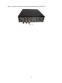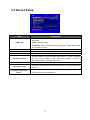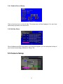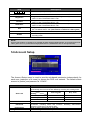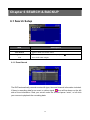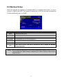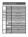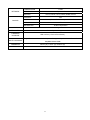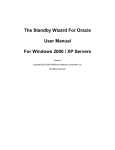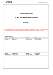
1
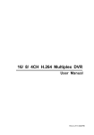
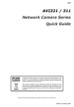
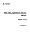
4 CH H.264 Multiplex DVR User Manual VER.:1.0, P/N: R040182A/1 This symbol is intended to alert the user to the presence of unprotected “Dangerous voltage" within the product's enclosure that may be strong enough to cause a risk of electric shock. This symbol is intended to alert the user to the presence of important operating and maintenance (servicing) instructions in the literature accompanying the appliance. WARNING TO REDUCE THE RISK OF FIRE OR ELECTRIC SHOCK, DO NOT EXPOSE THIS APPLIANCE TO RAIN OR MOISTURE. NOTE: This equipment has been tested and found to comply with the limits for a class digital device, pursuant to part 15 of the FCC Rules. These limits are designed to provide reasonable protection against harmful interference when the equipment is operated in a commercial environment. This equipment generates, uses, and can radiate radio frequency energy and, if not installed and used in accordance with the instruction manual, may cause harmful interference to radio communications. Operation of this equipment in a residential area is likely to cause harmful interference in which case the user will be required to correct the interference at ones own expense. Disposal of Old Electrical & Electronic Equipment (Applicable in the European Union and other European countries with separate collection systems) This symbol on the product or on its packaging indicates that this product shall not be treated as household waste. Instead it shall be handed over to the applicable collection point for the recycling of electrical and electronic equipment. By ensuring this product is disposed of correctly, you will help prevent potential negative consequences for the environment and human health, which could otherwise be caused by inappropriate waste handling of this product. The recycling of materials will help to conserve natural resources. For more detailed information about recycling of this product, please contact your local city office, your household waste disposal service or the shop where you purchased the product. I All the safety and operating instructions must be read before the unit is operated. Make sure to switch the power off before you install the DVR. There is the danger of an electric shock if the DVR is opened by an unqualified service engineer or installer. Avoid using the DVR outside of the reference temperature and humidity indicated in the specification. Avoid exposing the DVR to violent movement or vibration. Do not use or store the DVR in direct sunlight or near to any source of heat. Do not place any object into the holes used for air circulation. Always use the DVR in a well ventilated location to prevent overheating. Risk of explosion if battery is replaced by an incorrect type. Dispose of used batteries according to the instructions. II TABLE OF CONTENTS Chapter 1 FEATURES .........................................................................................................1 Chapter 2 PACKING DETAIL ...............................................................................................2 Chapter 3 LOCATION AND CONTROL ...............................................................................3 3.1 Front Panel Controls...............................................................................................3 3.2 Real Panel Connectors...........................................................................................4 3.3 Remote Controller...................................................................................................5 3.4 Mouse Control ........................................................................................................7 3.5 Playback Mode .......................................................................................................9 3.6 PTZ Mode .............................................................................................................10 Chapter 4 INSTALLATION .................................................................................................12 4.1 System Configuration ...........................................................................................12 4.2 Hard Disk Installation............................................................................................13 Chapter 5 BASIC OPERATION and MENU SETUP ..........................................................15 5.1 Main Menu Setup..................................................................................................15 5.2 Record Setup........................................................................................................16 5.3 Event Setup ..........................................................................................................17 5.4 Schedule Setup ....................................................................................................19 5.5 Camera Setup.......................................................................................................20 5.6 Account Setup ......................................................................................................21 5.7 Network Setup ......................................................................................................22 5.8 PTZ & RS-485 Setup ............................................................................................25 5.9 System Setup .......................................................................................................26 5.10 Utility Setup ........................................................................................................30 5.11 Diagnostic ...........................................................................................................31 Chapter 6 SEARCH & BACKUP ........................................................................................32 6.1 Search Setup ........................................................................................................32 6.2 Backup Setup .......................................................................................................35 Chapter 7 SPECIFICATION...............................................................................................36 Chapter 8 NETWORK SURVEILLANCE............................................................................38 8.1 AP Software Installation and Setup.......................................................................38 8.2 AP Software Operation .........................................................................................39 The author assumes no responsibility for any errors or omissions that may appear in this document nor does the author make a commitment to update the information herein. III Chapter 1 FEATURES H.264 compression ideal for saving HDD space Real time live display Up to 120FPS @ 360x240 recording (NTSC) Live display, record, backup, playback and network access at the same time Control methods: front panel, USB mouse, IR remote controller, and client viewer Intuitive GUI for easy configuration and menu driven operation 1 channel audio recording and playback Supports 1 SATA HDDs Pan / Tilt / Zoom camera control Data backup: USB devices and network (remote-site) Event triggered with email notification: motion detection, alarm, and video loss Support AP on your PC end for remote operation Multi-language OSD 1 Chapter 2 PACKING DETAIL 1. DVR 2. Client Viewer Software CD 3. User Manual 5. Power Cord 6. Power Adapter 8. SATA Cord 9. HDD Screws CONTENTS 1. DVR 2. Client Viewer Software CD 3. User Manual 4. Remote Controller 5. Power Cord 6. Power Adapter 7. Battery 8. SATA Cord 9. HDD Screws 2 4. Remote Controller 7. Battery Chapter 3 LOCATION AND CONTROL 3.1 Front Panel Controls Item Description 1 ESC/ BACKUP Exit various functions and menu screen Enter backup seletion menu 2 SEARCH Enter search menu screen, use Up/ Down button to navigate Press ENTER to access selected item 3 PIP Turn on picture-in-picture format, use Up/ Down button to navigate Press ENTER to access selected item 4 ZOOM Enable/ Disable double screen size display. Press ENTER to switch channels. 5 AUTO Enable auto mode, to skip channels Press MENU to disable auto mode 6 LED DISPLAY - REC DVR Recording. 7 LED DISPLAY- POWER DVR Power is on. 8 USB 2.0 The USB 2.0 port can be used to connect USB, mouse and USB storage device. 9 REC Start/ Stop recording. 10 PLAY Start playing back. MENU/ PAUSE Enter menu mode, use Up/ Down button to navigate menu screen. ( MENU/ Press to pause playback 11 12 13 14 15 16 17 ) IR SENSOR Input sensor for the remote control. RIGHT DIRECTIONAL Right Directional Button. Fast Forward Playback, Speed: 2x, 4x, 8x, 16x, 32x, 64x. BUTTON/ FAST ( / ) UP DIRECTIONAL BUTTON/ SLOW ( / Up Directional Button. Slow Forward Playback, Speed: 1/2x, 1/4x, 1/8x, 1/16x. ) DOWN DIRECTIONAL Down Directional Button. Stop Playback. BUTTON/ STOP ( / ) LEFT DIRECTIONAL BUTTON/ REWIND ( / ENTER/ MODE ( ) ) Left Directional Button. Fast Forward Playback, Speed: 2x, 4x, 8x, 16x, 32x, 64x. Switch to full screen and quad screen. 3 3.2 Real Panel Connectors Item Description 1 MAIN MONITOR BNC port for the main monitor. 2 VIDEO IN BNC input ports for cameras, 4 in total. 3 AUDIO IN RCA input port for an audio signal 4 NTSC/PAL SWITCH Switch between NTSC and PAL format. 5 LAN Network port. 6 VGA Output port for the VGA monitor (option). EXTERNAL I/O port (see below for pin definition) 7 EXTERNAL I/O 8 AUDIO OUT RCA output port for an audio signal 9 SPOT MONITOR BNC port to display full screen image of all installed cameras in sequence. 10 DC 12V Socket for a DC 12V input. 4 3.3 Remote Controller Remote Controller – Button Definition ○,1 LOCK ○,2 STATUS ○,3 REC ○,4 FREEZE Enable Keypad Function. Display Status. Start/ Stop Recording. Turn On/ Off Live Display FREZZE Function. Turn On/ Off Screen FREEZE Function. Enable/ Disable On Picture-In-Picture Format. ○,5 PIP Use Directional button to navigate the menu item, and press Enter button to enter the menu item. ○,6 OSD Turn On/ Off the Screen Display. 5 Enable/ Disable double screen size display. ○,7 ZOOM Use Directional button to navigate the screen display, and press Enter button to switch channels. ○,8 MENU/ Enable/ Disable Menu. Pause Playback. ○,9 Up Directional Button. / Slow Forward Playback, Speed: 1/2x, 1/4x, 1/8x, 1/16x. ○,10 ○,11 ESC / Exit Button. Left Directional Button. Fast Rewind Playback, Speed: 2x, 4x, 8x, 16x, 32x, 64x. ○,12 ○,13 ENTER/ MODE / Switch to Single Screen/ Quad Screen Display. Right Directional Button. Fast Forward Playback, Speed: 2x, 4x, 8x, 16x, 32x, 64x. ○,14 ○,15 PLAY / Start Playing Back. Down Directional Button. Stop Playback. ○,16 SEARCH Enter the SEARCH menu. Use Up/ Down Directional Button to navigate the menu item, press Enter button to enter menu item. ○,17 ○,18 ○,19 ○,20 ○,21 ○,22 ○,23 ○,24 ○,25 IRIS + PTZ Iris-Open. ZOOM + PTZ Zoom-In. FOCUS + PTZ Focus-In. AUTO In AUTO mode, all available channels will be cycled through in full screen. IRIS - PTZ Iris-Close. ZOOM - PTZ Zoom-Out. FOCUS - PTZ Focus-Out. COPY Enter the COPY menu. CAMERA Camera Select / Numeric Button. BUTTONS Press [+10] button to select channels. ○,26 MUTE ○,27 Switch to 1-CH Audio Out/ Turn Off Live Audio. ○,28 Switch to Quad Display. Switch to 9-Channel Display. 4-CH doesn’t support this function. ○,29 Switch to 13-Channel Display. 4-CH doesn’t support this function. ○,30 Switch to 16-Channel Display. 4-CH doesn’t support this function. ○,31 PRESET Lens PreSet Point Setup Press PRESET button+ 2 numeric numbers to save current lens location PLAY+ Numeric Number to move lens to preset point. ○,32 ○,33 TOUR Activate PTZ Preset Tour. PTZ Start/ Stop PTZ Control. 6 3.4 Mouse Control Live Mode Single Channel Display Move the cursor to the desired channel and double left click. Change from Single-Channel to Multi-ChannelDisplay Double left click Mouse – Menu Mode Enter Menu setup Right click Select/ Enter Left click Return to Previous Page Right click Mouse – Graphic Icons Resting the cursor on this icon will bring up the four (Main Menu/ Search/ Backup/ PTZ) menu icons. MAIN MENU SEARCH SETUP. BACKUP. PTZ CONTROL. Turn On/Off recording. PLAYBACK Resting the cursor on this icon will bring up five (PAUSE/ PIP/ ZOOM/ AUTO SEQ/ LOCK) display icons. PAUSE, to pause LIVE image PIP, picture in picture ZOOM, double the screen size AUTO-sequence LOCK, activate the key lock. 7 Full screen display, multiple clicking to switch channels Quad display. Mouse – GUI Hints and Tips Recording is on Live Audio is on Live Audio is off Motion detected on the channel Sensor triggered on the channel Video loss detected on the channel USB device detected DVR has been connected onto the Internet. Timer recording is on Red:Timer is set and recording has been started White:Timer is set but recording has not yet been started AUTO-SEQ is on 2X 2X zoom in is on FREZZE is on, screen is frozen LOCK is on PTZ control is on 8 3.5 Playback Mode Under the LIVE mode, the graphical icon [ ] will show up on the upper center of the screen and the operation panel (see below picture) will show up at right lower corner of the screen. You can drag the panel by mouse to place it on any location of your screen. Playback – Quick Function Icon Press「 / 」button to Fast Rewind Speed : 2x, 4x, 8x, 16x, 32x, 64x Press「 / 」button to Fast Forward Speed : 2x, 4x, 8x, 16x, 32x, 64x Press「PLAY」/ 「 」button to Play/ Pause Playback 「 / 」slow playback Speed : 1/2x, 1/4x, 1/8x, 1/16x 「 / 」stop playback Speed : 1/2x, 1/4x, 1/8x, 1/16x Playback channel by channel with snap shot display Full screen display Quad display 9 3.6 PTZ Mode Under LIVE mode, PTZ icon [ ] will appear on the upper left of the screen or be re-located on any place of your screen by dragging the mouse. PTZ – Remote Controller Control / SLOW Move PTZ up. / Move PTZ down. / Move PTZ to the left. / Move PTZ to the right. ZOOM + PTZ zoom-in. ZOOM - PTZ zoom-out. FOCUS + PTZ focus-in. FOCUS - PTZ focus-out. IRIS + PTZ iris-open. IRIS - PTZ iris-close. TOUR Activate PTZ pre-set tour. PRESET + NUMBER PLAY + NUMBER To save a preset location Press PRESET and a number key. DVR will save the current location. To go to a preset location Press PLAY and a number key. DVR will move to the preset location. ZOOM Set current PTZ location as the start of the line-scan. PIP Set current PTZ location as the start of the line-scan. FREEZE Activate line-scan. 10 PTZ – Quick Function Icon Exit PTZ Mode and back to the LIVE mode Preset number N. (1~64) Go to preset number N. Set current PTZ location at preset number N. [TOUR] icon, click to activate preset tour Same as [PIP]. Set current PTZ location as the starting point of the line-scan. Same as [FREEZE]. Activate line-scan. Same as [ZOOM]. Set current PTZ location as the ending point of the line-scan. To move PTZ in 360° PTZ zoom in or PTZ zoom out PTZ focus in or PTZ focus out. PTZ IRIS open or PTZ IRIS close. Below functions needs support from specific PTZ. Please check the user manual of your PTZ manufacturer for detail. AUX 1. [AUTO] +「1」 AUX 2. [AUTO] +「2」 AUX 3. [AUTO] +「3」 AUX 4. [AUTO] +「4」 AUX 5. [AUTO] +「5」 AUX 6. [AUTO] +「6」 AUX 7. [AUTO] +「7」 AUX 8. [AUTO] +「1」 [Backup] icon, click to customized function. 11 Chapter 4 INSTALLATION 4.1 System Configuration 12 4.2 Hard Disk Installation Step 1 : Remove the 3 screws from DVR as cycled below (PIC 1). (PIC 1) Step 2 : Remove the front cover from DVR as indicated by the arrow (PIC 2). (PIC 2) Step 3 : Place the HDD on the HDD plate and connect the power and the SATA cables (PIC 3). (PIC 3) 13 Step 4 : Screw the bottom of the DVR as indicated as cycled (PIC 4). (PIC 4) 14 Chapter 5 BASIC OPERATION and MENU SETUP 5.1 Main Menu Setup To enter the main menu and setup the DVR, please log-in account and enter user password. The default password of the administrator is “123456”. Please refer to “Account Setup” for related setup of other log-in users. Main Menu – Mouse Control Switch between capital and small letters. / Switch between numbers and letters. Press to cancel the setup, and re-choose the login account. Delete the last character. Enter to identify the password. It will enter the setup menu if the password is verified. Main Menu – Remote Control ler and Front Pannel Control Switch to different options under one item Switch to different items MENU ESC ENTER Save setup and back to LIVE mode Back to Upper level of the menu Enter the menu, or display virtual keyboard 15 5.2 Record Setup Item HDD FULL Description Select STOP to stop recording or OVERWRITE to reuse the HDD when HDD is full. [Stop]:Stop Recording [Overwrite]:Start to overwrite beginning from the oldest data of HDD, and continue to record. Schedule - Record Normal Enable/ Disable normal recording Schedule – Record Motion Enable/ Disable recording while Motion is detected Schedule – Record Sensor Enable/ Disable recording while Sensor is triggered Pre-Alarm Record Audio Record Video Preservation Quality & Frame Rate Setup… Enable/ Disable pre-event recording while motion or sensor is triggered but not in the recording mode. This option decides if save the pre-recording time 10 seconds data or not. Enable/ Disable Audio recording. Information stored within the HDD is preserved for only a specified length of time. Setup the quality and frame rate for each channel under normal recording and event recording type. 16 5.2.1 Quality & Frame Rate Setup Item Resolution Record Type No. Quality FPS Description Choose record resolution, this value will be used by all channels. You can setup quality and FPS separately for record type. Check/ uncheck the box will enable/ disable recording of that channel. Choose from Lowest/ Low/ Normal/ High/ Highest. Choose recording frame rate. 5.3 Event Setup Item Alarm Duration (Seconds) Description Set up alarm duration in seconds (can not be set to 0 seconds). Drag the white bar or press ♃☹ to adjust value. Motion Setup Enter to set up motion detection Sensor Setup Enter to set up sensor detection 17 5.3.1 Motion Setup Item Description Motion Detection Motion Popup 1 2 3 4 Selected Channel Turn Check the box to Enable/ Disable Motion Detection for all channels. Check the box to Enable/ Disable popup screen function for all channels. When motion is detected in LIVE mode, the detected channel image will popup in full screen display. You can setup independently for each channel. Check the box to Enable/ Disable motion detection for each channel. Object Size Drag the white bar or press ♃☹ to set up Object Size from value 1 to 15 for each channel. The lower value you set the higher sensitivity it will be. Sensitivity Drag the white bar or press ♃☹ to set up Sensitivity from value 1 to 15 for each channel. The lower value you set the higher sensitivity it will be Motion Area Setup Enter to setup motion detection area 5.3.1.1 Motion Area Setup There are 16x12 partitions in motion detection area. Under initializing status, motion detection area is in the entire screen. Red colored area is detected; yet the undetected area is transparent. It is purple while network is connected. Item Description LOCK / ZOOM Press LOCK / ZOOM to select the entire screen as detection area. MUTE / PIP Press MUTE / PIP to deselect the entire screen as detection area. STATUS Switch between “select” and “deselect” for cursor-dragging function ENTER Press to activate selected area with assigned status MENU Press to save the setup and leave ESC Press to cancel the setup and leave 18 5.3.2 Sensor Setup Item Sensor Detection Description Check the box to Enable/Disable sensor detection for all channels. Sensor Popup Check the box to Enable/Disable popup screen function for all channels. When Sensor is detected in LIVE mode, the detected channel image will pop up in full screen display. Sensor Polarity Click or press ▼ to select between HIGH/ LOW voltage for triggering sensor detection or OFF to turn off polarity for each channel Low Polarity:Sensor has not been triggered. When connected, sensor will be turned on. High Polarity:Sensor has been triggered. When connected, sensor status will be turned off. Off:Sensor is deactivated, and will not be turned on/off. 5.4 Schedule Setup Apart from manual recording, you can also setup the recording time by weeks and schedule recordings include: normal, motion detection, and sensor detection. Item Page Holiday Setup View Event Setup Description Click or press ▼ to select Page. Each page provides 10 schedules for setup. 5 pages in total. Enter to setup holiday, maximum up to 50 days. View Normal/ Motion / Sensor Setup. 19 5.4.1 Schdule Record Setup Click on the time icon on the left side. The setup menu will be displayed. You can have detail setup by dates, time and event. 5.4.2 Holiday Setup Since holidays are different between countries and regions, you can setup the holiday of your location accordingly (Maximum Setup: 50). 5.5 Camera Setup 20 Item 1 2 3 Description 4 Mask Brightness Contrast Saturation Hue Name Volume You can setup independently for each channel. Check the box to Enable/ Disable mask function for LIVE mode Drag the white bar or press ♃☹ to adjust Brightness of your camera from value 1 to 255. The default value is 128. Drag the white bar or press ♃☹ to adjust Contrast of your camera from value 1 to 255. The default value is 128. Drag the white bar or press ♃☹ to adjust Saturation of your camera from value 1 to 255. The default value is 128. Drag the white bar or press ♃☹ to adjust Hue of your camera from value 1 to 255. The default value is 128. (This function is ineffective in PAL system). Set up name of each channel. Select to adjust audio volume for CH1 to CH 4 under LIVE mode and recording mode. NOTE! Network LIVE videos are unable to be switched off when applying Mask function. To avoid network LIVE videos, please use User permission mask playback features (Administrator has no such permissions). 5.6 Account Setup The Account Setup menu is used to provide role-based permission independently for each user (maximum of 4 users) to access the DVR over network. The default admin account is [admin] and password is “123456”. Item Description Auto Lock After one minute without any action, the DVR will switch to LIVE mode automatically. Auto lock can function differently according to the setting below. Function Auto Logout Key Lock Setting No. Password Permissions Change Admin Password Key lock ○ ○ Key unlock ○ × Disable × × Check to activate the user’s account. Enter to set up password for each user. Password must be at least 8 characters, including letters and numbers. Resetting Adiminstartor password must also be at least 8 digits. Enter to setup Permissions for each user. Enter to change administrator’s password. 21 NOTE! 1: When logged out automatically, you will have to operate in limited authority such as operations like: Freeze the screen, Picture in picture, Zoom in/ out, switch between channels…etc. If you need to enter the Setup menu, Search menu, backup menu, Record…etc, user’s account and password are required. 2: When the key lock is activated automatically, remote control and mouse may not function unless entering verified password, remote-site will not be able to operate all the features (including toolbar). 3: [○] : Enable the function, [×] : Disable the function. 5.6.1 Permission Setup The Account Setup is set to provide individual user (maximum of 4 users) role-based permissions, including access to Setup menu, Network operation, PTZ function, Playback, Utility, Backup and Mask on specific channels while playing back. 5.7 Network Setup Item Connect type Description Setup mode for network connection: DHCP、LAN、ADSL. HTTP Setup Enter to set up HTTP for remote access into DVR. DDNS Setup Enter to Enable/ Disable DDNS function and set up. Mail Setup Enter to Enable/ Disable Email notification and setup. 22 5.7.1 Networking Setup The DVR supports DHCP, LAN and ADSL access for network connection. 5.7.1.1 DHCP If the DHCP option is used for DVR network connection, an IP address is assigned by the DHCP server automatically. 5.7.1.2 LAN Select LAN for network connection, the following information is required. Item IP Address Subnet Mask Gateway DNS Description Enter IP address provided by ISP Enter IP address of Subnet Mask provided by ISP Enter IP address of Gate way provided by ISP Enter DNS address provided by ISP. (Note: The correct DNS address must be entered for DDNS function). 5.7.1.3 ADSL Select ADSL for network connection, the following information is required. Item Description User Name Enter user name provided by ISP Password Enter password provided by ISP 23 5.7.2 HTTP Setup Item Enable HTTP Server Description Check to enable HTTP server. Users can remotely access into the DVR over the network if the HTTP function is activated. Port Enter a valid port value from 1 up to 65000. The default value is 80. 5.7.3 DDNS Setup Item Description Enable DDNS Check/ Uncheck to Enable/ Disable DDNS function. DDNS Server Enter the registered SMTP Server: DYNDNS.ORG, NO-IP.ORG, CUSTOM.COM SMTP Server Enter the registered SMTP Server. User Name Enter user name. Password Enter password. 24 5.7.4 Mail Setup E-mail can be used as a form of notification when an event occurs (VLOSS, MOTION, and SENSOR). Item Enable E-mail Notification SMTP Server Description Check the box to enable/disable E-mail Notification function. Enter to set up SMTP Server name. User Name Enter to set up User Name. Password Enter to set up Password. Sender E-mail Enter to set up e-mail address of receivers. E-mail address Enter to set up e-mail addresses for up to 10 receivers individually. Trigger Event Enter to select events to send out E-mail notifications when below circumstances happen: Motion, Sensor and Vloss (Video Loss). 5.8 PTZ & RS-485 Setup The DVR allows users to control PTZ functions of your camera. To enable PTZ function, the 485 cable should be connected to the RS-485 port of DVR. 25 Item Enable PTZ Protocol Description Click the box to Enable/Disable PTZ function for each channel. Set up the protocol of PTZ cam. The supported protocol are PELCO-P, PELCO-D, and KND PTZ ID Baud Rate Click or press ♃☹ to set up PTZ ID. The valid ID value is from 1 to 64. Select Baud Rate for PTZ from 2400、4800、9600 5.9 System Setup Item Description DVR Name The name of DVR will be shown when users login from remote access. DVR Location Language Auto-Seq Interval The location of DVR will be shown when users login from remote access Click or press ▼ to select OSD language. Click or press ♃☹ to set up duration time in seconds for the interval ( Seconds) between channels under Auto-Seq mode. Remote ID Preserved Function. Display Setup Date/Time Setup Buzzer & Relay Setup Spot Setup Enter to set up Display Enter to set up Date/Time Enter to set up Buzzer & Relay Enter to set up Spot 26 5.9.1 Display Setup Item OSD DVR Status Description Turn On / Off OSD display Turn On / Off DVR illustration and record status display Date/Time Turn On / Off date and time display Channel Name Turn On / Off channel name display Border Set Set up the color of border in LIVE , PLAYBACK mode.(black, dark grey, light grey, and white) 5.9.2 Date/ Time Setup Item Description Hour Format 12HOURS/ 24HOURS Date Format MM-DD-YY/DD-MM-YY/YY-MM-DD Date/Time Position Change Date & Time Time Zone Setup Internet Time Setup Choose the position of Time and Date display Setup time and date of DVR Set up GMT and Daylight Saving Time. Setup automatic synchronization with internet server 27 5.9.2.1 Change Date & Time Users are allowed to setup date and time of the DVR. 5.9.2.2 Time Zone Setup In time zone setup, users can change the time zone and activate Daylight Saving Time function according to your DVR location. Item Select Time Zone Daylight Saving Time Description Enter to modify GMT from GMT- 13 to GMT+ 13 Turn On/ Off Daylight Saving Time 5.9.2.3 Internet Time Setup Synchronize your DVR time with internet time server. Item Description Check to enable DVR automatic synchronization function. Select this Automatic Synchronization option to enable the function, DVR will automatically synchronize the time upon rebooting or by every 24 hours after booting. Update Now Date and Time show on DVR will immediately correspond with those in internet server. 28 5.9.3 Buzzer & Relay Setup Item KEY TONE Relay Switch Connection Buzzer Duration ALARM BUZZER ALARM RELAY Description Enable/ Disable keystrokes. Set relay signal to be Normal Close (N.C.) or Normal Open (N.O.). Set up the duration from 1~999 seconds. Enable/ Disable buzzer operation when the alarm is triggered for sensor, motion and vloss (Video Loss). Enable/ Disable the signal to be sent to the RELAY OUT blocks when the alarm is triggered for sensor, motion and vloss. 5.9.4 Spot Setup The DVR has two modes of video output; one is the main video output, the other is spot video output. SPOT setup is for controlling orders of channels that the system cycles through in SPOT mode. User can monitor every channel in the SPOT mode. Item Description Channels display in spot for three different modes: MANUAL: Select channels to display manually, select channels will be transfered to the SPOT monitor. SPOT MODE SEQUENCE: Auto-sequence for all channels in order. EVENT: Interval (Seconds) Skip Video Loss Channel Display channels with event occurred. The duration interval time between channels is in seconds under SPOT mode (can not be set to 0 seconds). Whether to skip channels without video signal. 29 5.10 Utility Setup Item HDD Initialization Description Select to enter hard disk initialization menu. Please stop recording before entering this menu. Enter the menu, system will show all the data (model/ volume) of HDD that is installed in the DVR. Check the HDD you’d like to initialize, then press “Start”. HDD initialization is successful when the status shows “Succeed”. USB Initialization Clean up all data on USB. Enter USB initialization and press “YES” to clean up all data on your USB. The initialization is done when it shows “Succeed”. System Recovery Reset System Events Copy Setup to USB Restore system default values. Reset all the recording events in the DVR. Copy configuration to a USB device. There will be a file named “sdvr.config” on your USB. Download Setup from USB Upgrade Download configuration from a USB device into DVR. Upgrade DVR through USB. Please stop recording and backup setup configuration before upgrading. System will reboot automatically when the upgrade is completed. NOTE! DO NOT TURN OFF POWER OR UNPLUG USB DEVICE DURING THE UPGRADE as it may cause incomplete firmware upgrade and damage to the DVR. 30 5.11 Diagnostic Item Version IP Address Description The current firmware version of DVR The connected IP address of DVR. If disconnected from network, the screen will display” NETWORK DISCONNECT”. MAC Address MAC Address of DVR HDD Volume The capacity of HDD HDD Used Rate Percentage of space used on HDD. Shows HDD status. USING means the HDD is now used for recording. HDD Status GOOD/ BAD means the HDD has a known/ unknown format for the DVR. (Note: Please initialize your newly-installed HDD before using it, otherwise it can be recognized as BAD by the DVR). Format Time The latest format time of HDD 31 Chapter 6 SEARCH & BACKUP 6.1 Search Setup Item Description Event Search Press to enter event search menu. Time Search Press to enter time search menu. Select Playback Channels 1~4 Check the desired channels to playback; uncheck channels to show LIVE video images. 6.1.1 Event Search The DVR automatically records events with type, time and channel information included. If there is recording data for an event, a yellow signal icon will be shown on the left side of time information. Rest your cursor under the line and press “enter”, or left click your mouse to playback the recording data. 32 Item Criteria Page Date/Time Description Setup conditions of the event search function Convert pages of events Date/ time when the event occurred. Event type, defined as following: Event Type VLOSS : Video Loss MOTION : Motion Detected SENSOR : Sensor Detected REMOTE IN : User log-in over the network REMOTE OUT : User log-out over the network POWER ON : System Rebooting KEY LOCK : System key is locked KEY UNLOCK : System key is unlocked HDD FULL Channel : HDD is FULL The channel where the event occurred. 6.1.1.1 Criteria Setup for Event Search The amount of events can be numerous. Therefore, you can facilitate event sorting by setting up “criteria”. Setup “start time” and “end time” for each event search, then the search result will be limited to this specific period of time. Only events and channels that are checked will be sorted in event search as well. 33 6.1.2 Time Search TIME SEARCH, you can search for a specific time of the recording data to playback. Dates with recording are shown by data marked with a red square [ □ ]. System will start playing back according to the date that you’ve selected. Calendar will be shown by using mouse to click on “year” and “month”. Click “date” to display recording time of that specific date with time bar. You can change time (hour/ minute/ second) or click on a specific time of time bar by mouse then press “YES”. DVR will playback the selected recording data. 34 6.2 Backup Setup User can back-up any segment of recorded data in a specified time frame. To do so, connect a USB to the DVR. The format of backup file is IRF file and can be played by “DVRemoteDesktop.exe” or “iCMS”. Item Description From Backup file starting time To Backup file ending time Select USB as the backup device Device Free Space Recalculate the available space of backup device Refresh Calculate Start NOTE! The available space in your backup device Calculate the size of backup file Start backup operation. Be sure to calculate the size of backup file BEFORE operating backup. Do not unplug the USB device or turn off the DVR during the backup process to avoid unrecoverable error. When backup is completed, you need to re-plug in order to insure proper function. 35 Chapter 7 SPECIFICATION VIDEO SYSTEM VIDEO NTSC/ PAL Selectable INPUT 4CH BNC LOOP N/A VIDEO OUTPUT 1CH, BNC SPOT OUTPUT 1CH, BNC VGA OUTPUT AUDIO TERMINAL CONTROL STORAGE DISPLAY Optional INPUT 1CH, RCA OUTPUT 1CH, RCA SENSOR 4 Inputs/ 1 Outputs RS-485 INTERFACE Pan/ Tilt/ Zoom Camera MOUSE USB Mouse YES IR CONTROLLER DEVICE Supports SATA Hard Disk x1 DVD WRITER N/A DIVISION 1,4 ZOOM 2X OSD Graphic OSD COMPRESSION H.264 720x480, 720x240, 360x240 (NTSC) RESOLUTION RECORDING 720x576, 720x288, 360x288 (PAL) FRAME NTSC 30, 60, 120FPS RATE PAL 25, 50, 100FPS QUALITY RECORD MODE MOTION DETECTION Highest/ High/ Normal/ Low/ Lowest Manual, Schedule, Event (Motion Detection, Sensor, Video Loss) User selectable motion detection area for each camera individually Sensitivity: 5 levels PRE-ALARM 16 MB POST-ALARM 16 MB WATERMARK N/A SEARCH MODE PLAYBACK SPEED Time, Event Normal, REW&FF[2x/4x/8x/16x/32x/64x], Picture to Picture, Pause INTERNAL HDD EXTERNAL N/A 36 COMPRESSION NETWORK BACKUP H.264 INTERFACE Internal Exploerer Browser SERVICE TCP/ IP, SMTP, HTTP, DHCP, DDNS, PPPoE INTERNAL N/A EXTERNAL USB 2.0 (1 Port at Front Panel) : USB Flash Driver NETWORK YES BACKUP FILE H.264 Compression MONITORING Software Watchdog RECOVERY Auto-Reboot By Watchdog FIREWARE UPGRADE MULTI-LANGUAGE USB 2.0 Port (1 Port at Front Panel) English/ Traditional Chinese/ Italian/ Japanese/ Portuguese/ Spanish/ German/ French/ Russian/ Simplified Chinese/ Polish DIMENSION 188mm (W) x 54mm (H) x209mm (D) POWER SOURCE DC 12V 37 Chapter 8 NETWORK SURVEILLANCE 8.1 AP Software Installation and Setup Step 1:Enter the IP address of the DVR in the IE browser. Step 2: A window will pop-up. Please enter the user name and password. Default user name is admin and password is 123456. Other related setup about user account and password, please refer to “5.6 Account Setup“. 38 Step 3: You’ve logged into the DVR 8.2 AP Software Operation User-friendly operation, DVR remote interface provides the DVR with the same local client interface. 39 8.2.1 Remote Record Click Record icon to select between 3 recording options (Record On/ Off, Record to Local…, Screen Snapshot [F2]). Record switch can activate DVR client to record, record to local client can be backed up onto the PC, may also use snapshot to capture video image onto the PC. 8.2.2 Lock Click Lock icon to lock remote-site function and to unlock, account and password must be entered all over again. 40 8.2.3 Full Screen Click Full Screen icon to enlarge the screen to full screen display. 8.2.4 Camera Name A variety of languages can be used to setup the PC client camera names; and simultaneously changes the display of the local client DVR. 8.2.5 Remote-Site Backup Select backup function to backup the data to PC. 41