1
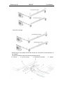
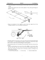
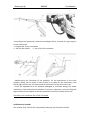
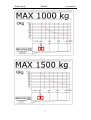
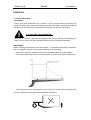
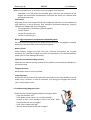
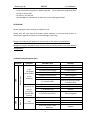
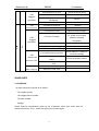
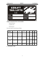
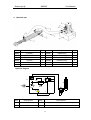
Tuckaway Lift
EZLIFT
User Manual
TUCKAWAY LIFTING SERIES
INSTALLATION INSTRUCTION
1
Tuckaway Lift
EZLIFT
User Manual
TABLE OF CONTENTS
INTRODUCE ···········································································································3
INSTALLATION ·······································································································4
1. Preface
·········································································································4
2. Parameter ······································································································5
Electro-hydraulic equipment
Hydraulic power pack:
Vehicle and tailgate limits
3. Mounting
·····································································································5
Installation Procedures
Verification by the installer
Markings safety
OPERATION
·········································································································12
1. General information ·························································································12
2. Operating step ·································································································14
3. Maintenance ····································································································14
4. Troubleshooting diagnosis chart ·····································································15
SPARE PART
·········································································································17
1. Attention ········································································································17
2. Mechanical part ·······························································································18
Crossbeam
Lift-arm
Platform
3. Hydraulic part ································································································22
4. Electrical part ·································································································23
Repair and Warranty …………………………………………………………………………………………….24
2
Tuckaway Lift
EZLIFT
User Manual
INTRODUCE
The EZLIFT-tailgate is electro-hydraulically driven. An electric motor which gets its
power from the truck’s battery drives a hydraulic pump which supplies oil via hoses
and pipes to the working hydraulic cylinders. The system is steered by electrical
valves. The hydraulic power unit with all details is built into the lift’s support frame.
The control system is built into a separate box. Both systems are easy to reach for
service and maintenance.
Manufacturer Responsibility:
We have already released the platform installation, testing dimension and
description and the vehicle adjustment (the dimension and description are required
by the vehicle manufacturer).
However, the manual is not limited on and our keeps the right changing the
productions without notification in advance and without modifying data on this
manual.
We will take the responsibility on designing and manufacturing the products. We will
not be responsible for the misuse or the damages due to installation the improper
platform on the vehicles.
Any modification on platform basic construction must be proposed with written
requirement to the technical department. The technical department must reply
and follow up timely.
The guarantee will terminate automatically if the item is not observed.
Our principle: excellent work to produce high quality products and promote services
to satisfy our customers.
3
Tuckaway Lift
EZLIFT
User Manual
INSTALLATION
1. Preface
Read the user manual and all relating instructions on installation the tail-lift from
vehicles manufacturer before installation the tail-lift on the truck.
The installation must be operated by the experienced technicians approved by
Ezilift Co., Ltd, to ensure the specifications mentioned in the manual.
The installer is fully responsible for installing the tailgate on the vehicle.
In particular, please refer to the vehicle manufacturer’s instructions and our
recommendations for any welding or drilling operations to be carried out on the
vehicle chassis.
Working Clothes
- Do not wear loose clothes preventing blocked by moving parts
- Wear gloves and safety shoes during the operation
- Wear safety cap if possible when working under the car, even cloth caps can
prevent slightly scratches (if somebody do not like to wear safety caps).
- Wear goggle and face shield when operating the polishing or such machine
and using paintings or solvent.
Do not wear finger ring, watches or necklace during the operation
preventing blocked or conducted.
Working Site
Working in a tidy and clean place will get the operator comfortable (sometimes
the customer will standby during the installation). Moreover, such working place
might reduce the damages.
- Only use the tools in good conditions.
- Place the components disconnected separately and from the vehicles to
prevent the accident happened.
- Be sure the ventilation when using the paints or solvent.
- Use the lifting equipment (jack, trolley and crane etc) with correct range in a
suitable manner.
- Use the lifting tools (strap, hook, rope and chain etc) in good condition with
correct ranges in a suitable manner.
- Connect the hydraulic equipment properly. Be sure no pressure in the
system before connecting the hydraulic equipment.
- Do not use the cleaning agent of gasoline, corrosive or alcohol. The
inflammables and harmless solvent will be used for cleaning.
- Wear goggle when cleaning the parts with the compressor.
-
Clean the tools each time after using.
Keep working site clean
4
Tuckaway Lift
-
EZLIFT
User Manual
Clean the hydraulic oil, lubrication oil, paints, solvent, and fuel residuals.
2. Parameter
Electro-hydraulic equipment
Control box voltage:
Control box fuse:
Power support:
Battery capacity:
Alternator capacity::
12 or 24V DC
10A
12 or 24V DC
12V:185Ahmin
24V:2×12V -185A
14V-90Amin
28V-70Amin
Hydraulic power pack:
Motor rating power:
Max. Consumption:
12V:
24V:
12V:
24V:
1600 Watt
2000~2200 Watt
Amp≥200
Amp≥130
8L
Held by 4 bolts and nuts
172 bar
Viscosity at 40℃=32mm2/s
Tank capacity:
Power pack support::
Max setting pressure for relief valve:
Recommended hydraulic mineral oil:
(NOTE:The electro-hydraulic power pack may be deteriorated if another type of oil
is used. )
3. Mounting
Before welding on the vehicle, disconnecting all the wire connected to the battery (+).
Installation Procedures:
- Dismantle the attachments on the two sides of the rear truck frame. Then, fixing
the extension—plate.
As body in the carriage:
5
Tuckaway Lift
EZLIFT
User Manual
Out of the carriage:
Mark a tag on the middle of the floor of the rear of vehicle and the platform of
the tailgate.
- Put on the platform with the tuckaway without spring.
2 – lift-arm ; 3 – pin for spring ;
4 –Cantilever assemble ; 5 – Spacer
-
6
Tuckaway Lift
EZLIFT
User Manual
- Lifting the platform to the level position with the floor of the rear of vehicle by
forklift.
- Put on spacer between the truck and the platform. Then, pushing and fixing this
position. B = 12
-
Lifting the crossbeam of the tailgate by jacks. Check the upper face of the
crossbeam whether it is or not parallel to the ground.
- Bolting the plates on the chassis or can use if these hoses have been good drilled
on the vehicle. It is recommended if possible to weld them onto the sub frame
(6mm continues weld seam), after bolting the mounting plates.
- Put the power pack on the crossbeam of the tuck-away. Check the oil level of the
oil tank.
- Fixing the control boxes on the rear of the vehicle. (Note: it must be one safety
side near the road.) Then, Put Circuit sentry on the frame between battery and
power pack. Connect the control unit to the battery properly according to the
circuit diagram attached.
1 -- Wires of the power pack ;3 -- Circuit sentry ; 6 -- Heat shrinkable tube
7
Tuckaway Lift
EZLIFT
- Install the springs
1 --springs
2 --pin of the platform
3 --“U” bolts
- Adjustment the platform
1 -- Ram bolts
2 -- cantilever
8
User Manual
4 -- nuts
Tuckaway Lift
EZLIFT
User Manual
- According to the parameters (Vehicle and tailgate limits), removal of a right angle α
on the truck beam
- Fixing the bar on the crossbeam
1 -- Bar for the wheels
2 -- bar of the lift crossbeam
- Double-check the functional of the platform. Fix the attachment of the truck
properly. Notify the car owner in time if there is no space for the attachment. Test
the tail light of the truck, the fixture and all connections of the tail of the truck.
- Check the appearance of the platform damaged or scratched during the whole
installation. Clean and paint the platform if necessary. Moreover, insert the flag and
tag on the back of the platform and the operation instruction and the notice etc.
Therefore, the installation for LIFTER is finished.
Verification by installer
The installer shall confirm the compatibility between the lift and the vehicle.
9
Tuckaway Lift
EZLIFT
User Manual
Test of operation and safety function:
After the static and dynamic tests have been completed, all function of the tailgate
and operations of all safety devices are verified. These tests exclude hydraulic and
electrical parts, such as safety valve and insurance assembly. (These items are the
subject of a manufacturer’s type test.)
Measurements of lowering speeds shall be carried out with the platform carrying
its maximum load; all other measurement of speeds shall be carried out with the
platform unloading.
Test to verify that the tail-lift can not lift excessive load:
A load of 125% of the maximum load is applied to the platform, positioned at
ground level. Actuate the “UP” control and verify that the platform does not lift
(tilt up is permissible).
Check the appearance of the platform damaged or scratched during the whole
installation. Cleaning and paint the platform, before installing the safety marks.
Markings safety
EZLIFT markings must be installed on the tail-lift:
In the tail-lift packing, there are:
- The bumper to be fixed on lift-arm
- Flags to be attached on the platform
- Stickers to be placed on the platform
- Strips to be stuck on the sides of the platform
Road safety:
Place a safety hinge hooks between the platform and the vehicle body to prevent
the lifter from falling down in case of accident.
Then the bumper is installed for the lift-arm.
Load charts: Place a load chart close to each control box of the tailgate. Load charts
are supplied in the tailgate packing.
10
Tuckaway Lift
EZLIFT
11
User Manual
Tuckaway Lift
EZLIFT
User Manual
OPERATION
1. General information
Remember:
Please read and understand the contents of this manual before operating the
equipment. And also, understand the functions of the tailgate, possible hazards and
dangers and the load limits and load positioning for that specific equipment.
IT’S ONLY ONE—MAN OPERATION
Never let an “outside” operates the tailgate when you are loading or unloading the
cargo. Or else, serious or fatal damage could result form improper operation.
IMPORTANT:
Before allowing the operator to use the liftgate,he should be thoroughly conversant
with the liftgate’s functions and usage according to the following:
- Be sure the vehicle is properly and securely stopped before using the tailgate.
- Each load should be placed in a stable position as close to the vehicle as possible.
- Do not overload. See rating label on the unit for the rated load. Remember that
this limit applies to both lifting and descending operations.
12
Tuckaway Lift
-
-
EZLIFT
User Manual
Do not to use the platform as a bridge for forklift.
This is not a passenger lift. Do not ride the lift with unstable loads or in such
manner that a failure would endanger you. The lift is not equipped with a
back—up system to prevent falling in the event of a failure.
- Never stand in or drill through or allow anyone else to stand in or move through
the area in which the lift may operate or into which an upset load might fall.
-
Improper operation of this lift can result in serious personal injury. Do not operate
unless you have been properly instructed and have read and are familiar with the
operation instruction. If you do not have a copy of the instructions please obtain
them from your employer, distributor or lessor, as appropriate, before you
attempt to operate the lift.
- Always inspect this lift for maintenance or damage before using it. If the major
parts damage or the platform is slippery, do not use the lift. Do not attempt to
repair it by yourself unless you are specifically trained.
- Lay people don’t try to repair, please!
- Please kind in mind; otherwise you need take your own responsibility.
13
Tuckaway Lift
EZLIFT
User Manual
2. Operating step
IMPORTANT NOTE:
When used for the first time, some irregular operation may be found (hammering,
vibrations, difficulties in handling the platform). This is normal. Correct operation is
the only way to let the tail lift smooth operation.
- Remove the platform safety hinge hook. Turn on master switch in the control
box.
- Press the button “down”, then the platform to fold out. Manually open the
platform.
- Operating the platform by control box or remote control.
- Load or unload.
NOTE: the load must always be positioned on the platform as close to the
vehicle as possible; the load must never overhang the edge of the platform;
Refer to the load chart in the present manual.
- Bring the platform into fold up position then lock it.
- Cut off the power using the main switch.
3. Maintenance
All maintenance operations must be carried out with the tailgate on the ground
(platform tilt to the ground), without any loads on the platform.
Foreword:
- Never spray pressurized water on the electro—hydraulic power pack and on the
outside control box.
- Use a brush or compressed air on these parts.
- The electro—hydraulic power pack is the weak point in your tailgate. Always make
sure that it is perfectly clean.
- An electro—hydraulic power pack drain is recommended, at least once a year.
Checking the oil level:
- Wait 15 seconds until the oil level settles when the platform tilts down the
ground.
- The oil must be between 3cm and 4cm from the top of the reservoir. If necessary,
top up with mineral oil.
Change oil:
- Change oil at least once a year.
- Use a good quality of hydraulic oil, ISO32. it is recommended not to mix oils from
14
Tuckaway Lift
EZLIFT
User Manual
different manufacturers; in all cases, never use engine oil or brake oil.
- Referable in the fall before the weather gets cold since the operation of the
tailgate will accumulate condensation and some dirt which can interfere with
the tailgate functions.
Lubrication:
All grease points must be generously and completely lubricate. For the condition of
high efficiency or work intensity, they should be lubricated frequently. Properly
lubricate the tailgate will ensure longevity.
- The equipment is fitted with 12 grease nipples;
- On the lift-arm
- On the lift-cylinder pins
- On the tilt-cylinder pins
NOTE: high temperature molybdenum disulphide grease.
We also recommend greasing the grease points each time the tailgate is washed,
especially if washed under pressure with detergents.
Battery check:
Check battery charge and make sure that electrical connections are in good
condition. An insufficient charge may affect the operation of the electro-hydraulic
power pack or even damage the motor.
Check the mechanical locking systems:
Check the mechanical locking systems of the platform (mounted by the builder) on
the vehicle body.
Tailgate structure:
Weld seams must be strictly checked.
Inspection tests:
Remember that the tests and inspections mentioned in the check booklet must be
made every 2 months. In case of anomalies, stop using your tailgate and contact
your nearest repair center.
4. Troubleshooting diagnosis chart
Please check the following points before looking for faults:
- Is the lift switched “on”?
- Is the battery main switch “on” and functioning?
- Is there a main circuit breaker in line to the lifter? Main
switch OK for the current supply?
- Is the fuse in power pack OK?
- Are the vehicle batteries OK and charged?
15
Tuckaway Lift
EZLIFT
User Manual
- Is the connection to ground in power pack OK;Is the connection to ground from
tail lift to vehicle OK?
- Oil level in oil tank OK?
- Any damages on mechanical or electrical such as damaged cables?
ATTENTION:
Please change oil after working on hydraulic unit.
Please turn off main switch of battery while working on the electrical system or
disconnect negative connection. Avoid to danger of burning.
Danger of accidents will happens if intervention in the electrical installation?
Dangerous injuries possible if short circuits arise caused by tools on the main battery
connections?
Troubleshooting diagnosis chart
No operation
Down
2.00
1.00
Function
Symptom
1.10
No power
to lift (power
circuit
problem)
Possible cause
1.11 Battery terminals dirty
1.12 Battery defective
1.13 battery discharged
1.14 circuit sentry off
1.15 ground connection
1.16 Circuit sentry defective
1.21 Wire terminal
1.22 Switch defective
1.23 Broken wire
Remedy
Clean & tighten
Replace
Charged battery
Fix overload & reset
Clean & tighten
Replace
Check for loose terminals
or broken wire
Crimp tightly to wire
Replace
Replace
1.24 Loose connection
Clean & tighten
2.11 defective valve in pump
2.12 Mechanical lockout
2.13 Also see 1.00
2.14 Flow control valve
defective
Replace
Check & correct
1.17 Power cable
1.20
Power to lift
but no
operation
(switch box
circuits)
2.10
No operation
16
Replace
Tuckaway Lift
EZLIFT
2.20
Sluggish
operation
3.10
No operation
UP
3.00
3.20
Sluggish
operation
2.21 Restriction in lines
Check for dirt or kinks
2.22 Oil too thick
Thin with diesel fuel -2T.
2.23 Flow control valve placed
backwards
2.24 Also see 2.13
3.11 Motor solenoids
3.12 Also see 1.00 & 2.00
3.21 Excessive load
3.22 Low oil supply
3.40
Won’t stay up
Correct
Replace
Remove excess weight
Add type A transmission
oil, check oil level with
platform lowered
completely
3.23 Cylinder leaks
Replace
3.24 Leak in plumbing
3.25 Also see 1.10, 2.20
Replace
3.31 Relief valve set too low
3.30
Motor runs
but won’t lift
User Manual
3.32 Down solenoid stuck
Open
3.33Also see 2.00、 3.20 &
3.23
Dirty valve seat in pump
Also see 3.23 & 3.24
Set at 2000 p.s.l. (Refer to
monarch catalog)
Check raise/lower switch
Flush clean or replace
SPARE PARTS
1. ATTENTION:
To order spare parts please do as follow:
- The tailgate model
- The tailgate Serial number
- The part number
- Voltage
Please find the manufacturer plate on the crossbeam, place your order with the
below information. Then , check the spare parts manual again.
17
Tuckaway Lift
EZLIFT
User Manual
Tailgate is comprised of three sub-assemblies:
- Mechanical part
- Hydraulic part
- Electrical part
The main materials and elements (Table):
Component
Material
C
Si
Mn
P
S
45
0.42~0.50
≦
≦
0.17~0.37 0.50~0.80
0.035 0.035
16Mn
0.12~0.19
0.17~0.37 0.70~1.00
≦
≦
0.035 0.035
65Mn
0.62~0.70
0.17~0.37 0.90~1.20
≦
≦
0.035 0.035
0.235A
0.14~0.22
0.30~0.65
≯
≯
0.045 0.050
≯0.03
2. MECHANICAL PART:
18
Cr
Ni
≦
0.2
5
≦
0.2
5
≦
0.2
5
≦
0.2
5
≦
0.2
5
≦
0.2
5
Tuckaway Lift
-
EZLIFT
User Manual
Crossbeam
REP
DESIGNATION
QTY
REFERENCE
01001
Crossbeam
1
16Mn
01002
Pins
2
45#
01003
Spacer
2
Nylon66
01004
Lock plate, pin
7
45#
01005
Mounting plate
2
16Mn
01006
Brake plate
2
16Mn
2
GB/T6183-86
8
45#
12
GB/T5781-86
12
GB/T95-85
01007
Self-lock nut
01008
Pins
01009
01010
Bolts
M30
M8×30
Flat washer
Φ8
01011
Pins
1
45#
01012
Spacer
2
Plastic
01013
Bracket, cylinder and lift-arm
6
16Mn
01014
Pins
12
45#
01015
Wheels
6
Nylon66
01016
Pins
1
45#
01017
Pins
2
45#
01018
Support tube
1
Q235
19
Tuckaway Lift
EZLIFT
User Manual
- Lift-arm
REP
DESIGNATION
QTY
REFERENCE
02001
Lift-arm
1
Q235,16Mn
02002
Copper bush
2
Copper
02003
Adjunct-arm
2
Q235
02004
Cantilever assemble
2
16Mn
02005
Pins
2
45#
02006
Self-lock nut
4
GB/T 6183-86
02007
“U” bolts 14
2
JB/ZQ 4321-97
02008
Lock plate
3
45#
02009
Pins
1
45#
02010
Copper bush
2
Copper
20
Tuckaway Lift
EZLIFT
User Manual
- Platform
REP
DESIGNATION
QTY
REFERENCE
03001
Bumper
1
Q235
03002
Extension plate
2
Q235
03003
Spring
2
65Mn
03004
Pins
2
45#
03005
Lock plate
2
45#
03006
Platform
1
03007
Connector
4
03008
Pins
3
45#
03009
Screw M8*15
2
GB/T70-1985
03010
spring
1
65Mn
21
Aluminum
6063-T5
Aluminum
6063-T5
Tuckaway Lift
EZLIFT
User Manual
3. Hydraulic part
Item
04001
04002
04003
04004
04005
04006
Descriptions
Cylinder
Electro-valve
Pipe Connector
Oil pipe
Oil tank
Relief valve
Item
04007
04008
04009
040010
040011
040012
Qty
1
2
2
1
1
1
Descriptions
Poppet assy
Motor
Relays DC12V/24V
Manifold assy
Air pipe
Air connector 90º
Qty
1
1
1
1
2m
2
Hydraulic diagram
6
b
a
9
8
4
5
3
2
P
T
7
1
Item
Descriptions
Item
Descriptions
1
Oil tank
6、7
Two position two way non -return stop valve
2
Filter
8
Hydraulic ram
22
Tuckaway Lift
EZLIFT
User Manual
3
Pump
9
Interface block
4
Motor
a
Release valve
b
Non -return duel - valve
5
Contact pin member
4. Electrical part
05001
05002
05003
05004
REP
DESIGNATION
ORDER NO.
05001
05002
Power button
Button (green, yellow)
WE017-3
WE016-4,WE016-5
05003
Hoist push button
WE016-2
05004
Fuse assembly
WE019-38
Electrical diagram
SA0
10A
FU2
FU1
150A
DC
UP
DOW N
SB1
SB2
KM1
KM
M
YV4
23
YV1
KM
KM1
Tuckaway Lift
EZLIFT
User Manual
KM —(motor)DC contactor ; KM1—(solenoid valve)contactor control;
YV1—(cylinder)solenoid valve; YV4—(power pack)solenoid valve;
Repair and Warranty
Repair
The returned parts for repair must be attached the tag, indicating the address in
details and the ranges of repair.
Guarantee
The returned parts must be followed with the shipping receipt or invoice. We will
check the parts damaged according to your instruction within the guarantee. Please
specify the reasons and fill in the certificate in details.
24