1
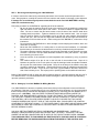
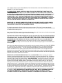
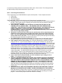
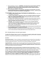
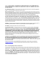
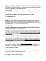
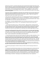
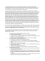
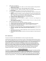
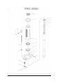
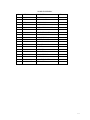
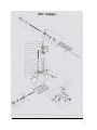
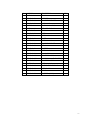
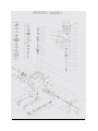
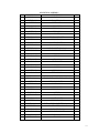
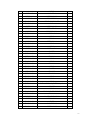
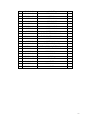
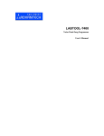
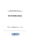
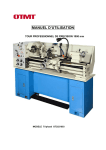
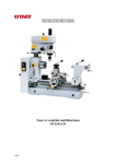
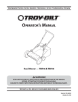
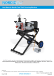
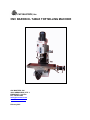
CNC MASTERS, Inc. CNC BARON XL TABLE TOP MILLING MACHINE CNC MASTERS, INC. 16031 ARROW HWY, STE. J IRWINDALE, CA 91706 PH: 626-962-9300 [email protected] www.cncmasters.com February 2011 THANK YOU FOR YOUR PURCHASE OF THE CNC BARON XL MILL. WE WISH YOU MUCH SUCCESS IN THE MANY APPLICATIONS THIS CNC SYSTEM CAN ACCOMPLISH. IMPORTANT: PLEASE READ ALL INSTRUCTIONS IN THIS USER MANUAL TO BECOME FAMILIAR WITH YOUR CNC BARON XL Mill. NOT FOLLOWING THE INSTRUCTIONS MAY RESULT IN THE DAMAGE OF YOUR PRODUCT AND VOID OUT YOUR WARRANTY WITH CNC MASTERS. IT MAY ALSO CAUSE SERIOUS INJURY OR UNNECESSARY DOWNTIME SINCE YOU MAY NOT BE COMPLETELY FAMILIAR WITH THIS PRODUCT. TABLE OF CONTENTS SEC 1. Receiving and Unpacking your CNC BARON XL SEC 2. Setting up your CNC BARON XL Milling Machine SEC 3. Connecting Electrical Power SEC 4. Hand-Held Remote Control with Joystick (Option) SEC 5. Connecting Motor Cables to Control Unit SEC 6. Accessories and Options: 4th Axis, Coolant Control, Quick Tool Change SEC 7. Self Help Support/Trouble Shooting Tips SEC 8. Maintenance SEC 9. Safety Warnings SEC 10. Specifications SEC 11. Operations and Parts List MASTER SOFTWARE MANUAL ---Installation of the Master Software and instructions on how to use it. 2 SEC 1. Receiving and Unpacking your CNC BARON XL It is best to remove the crate box by unscrewing the bottom row of screws around the perimeter of the crate. Using a partner, carefully lift crate box over the machine and inspect for damage or short shipment. If damage has occurred during shipment contact both the carrier and CNC MASTERS in writing within the next business day. Follow the procedure for the BARON XL regarding the lift of the machine: 1. Be sure to lower the machine head as close to the machine body as possible by cranking the right side handle on the lower part of the column. A screw-on handle is supplied with this order. Be sure to loosen the two hand screws on the left side of the machine head when cranking head into position. Tighten at desired level of the machine head. Use an engine hoist if a forklift or stacker is not available to pick up with fork under machine head between column and quill. Also use the four large bolts located at the left and right side the base of the machine to lift from there as well. While moving the CNC BARON XL, make sure to keep it balanced. 2. Do not place the CNC BARON XL in direct sunlight to avoid warping the machine, which can cause lack of accuracy. 3. Mount the CNC BARON XL to a sturdy table or a solid concrete foundation; it is advisable that the base you choose be constructed well to avoid any vibrations during the operation. 4. Thoroughly clean the machine, and then coat all bright metal with a light lubricant to prevent corrosion. CAUTION: DO NOT USE flammable cleaners to clean your machine. Any spark from machining can cause a fire. 5. Level the surface of the worktable on both lengthwise and crosswise by using a precision level. 6. Use medium weight oil for the oil can on the left side of the machine base. Squirt oil in between the grooves of the Z axis spline to keep the bearings inside the spindle lubricated. Oil may leak out at the bottom of the spindle. Pump oil on the ways of the machine every day you plan to machine an application. Grease ball screws monthly by rubbing grease along the shaft under the X table. To get to the Y ball screw, jog the saddle to the front, remove one side of the back way cover. Use a putty knife to spread grease on the shaft below the base. Bolt the CNC BARON XL Mill on either the optional machine stand or a sturdy workbench with four 3/8” or 1/2” diameter bolts. It is recommended that the workbench height be about 30 inches high depending upon the operator’s preference. SEC 2. Setting up Your CNC BARON XL Milling Machine Your CNC BARON XL has been completely tested at the factory before shipment to ensure all features are functional. Damage or components may go out of adjustment during shipment, so it is recommended that all components be checked and adjusted as necessary prior to connecting the CNC BARON XL to a power source. CAUTION: YOU WILL NEED TO REMOVE SHIPPING MATERIAL INSIDE THE CONTROL UNIT BOX BEFORE PLUGGING IN. FACING THE FAN OF THE CONTROL UNIT WITH THE TWO PORT CONNECTORS AND POWER CABLE SOCKET SHOWING AT THE BOTTOM OF THE CONTROL, USE A PHILLIPS SCREW DRIVER TO SLIGHTLY LOOSEN THE TWO LARGE PANHEAD SCREWS ON THE LEFT SIDE OF THE CONTROL BOX. SWING OPEN THE CONTROL COVER BOX TO THE RIGHT SLOWLY. IF THE POWER CABLE, USB CABLE, AND OPTIONAL HAND HELD REMOTE CABLE ARE PLUGGED IN, YOU WILL NEED TO UNPLUG THESE CABLES FIRST BEFORE OPENING COVER. YOU WILL SEE TWO/THREE PIECES OF CARDBOARD AND RUBBER BAND. CAREFULLY REMOVE THESE MATERIALS FROM THE CONTROL UNIT---WITHOUT “TOUCHING” THE PINS WHERE THE MOTOR CONNECTORS ARE PLACED OR THE CIRCUIT BOARD CARDS. PLEASE TOUCH GROUND FIRST TO DISCHARGE ANY EXISTING STATIC YOU MAY HAVE IN YOUR BODY BEFORE REMOVING THE SHIPPING MATERIALS FROM THE INSIDE OF THE CONTROL UNIT. 3 ANY HUMAN STATIC THAT DISCHARGES INTO THE MAIN CPU CARD OR DRIVERS MAY CAUSE DAMAGE TO THE ELECTRONICS. ALSO IMPORTANT: MAKE SURE EACH SMALL BLACK BOX (DRIVER WITH HEATSINK FOR EACH AXIS) IS SECURED WELL TO ITS OWN BLUE OR BLACK COLORED STRIP CONNECTOR. DO THIS BY LOOKING UNDERNEATH OF EACH DRIVER AND MAKING SURE THAT THE CIRCUIT BOARD INSIDE THE DRIVER IS FLUSH AGAINST THE LEFT SIDE OF THE BLUE OR BLACK CONNECTOR. IF NOT, TAKE ONE FINGER AND APPLY PRESSURE FROM THE RIGHT SIDE OF THE BLUE OR BLACK CONNECTOR, AND WITH OTHER HAND APPLY PRESSURE TO THE BACK SIDE OF THE DRIVER’S HEATSINK UNTIL THE CIRCUIT BOARD IN DRIVER IS FLUSH AGAINST THE LEFT SIDE OF THE BLUE OR BLACK CONNECTOR. MAKE SURE ALL ORANGE CONNECTORS FROM EACH AXIS MOTOR ARE PLUGGED IN WELL ON ITS OWN SET OF PINS BEFORE CLOSING CONTROL COVER AND POWERING UP. CLOSE THE BOX AND TIGHTEN THE TWO PANHEAD SCREWS. For shipping purposes the X and Y-axis motors are not mounted. The X and Y motors are already connected to the Control Unit, but need to be mounted on each axis accordingly. The brackets and motors are labeled with matching colors. Next, using a 5/32” Allen wrench, loosen the collar clamps at the end of each axis until collar clamp rotates freely. Do not loosen or remove large nut next to the clamp. Align each motor, with the cable pointing down, and work the motor all the way into the bracket and clamp. First, wipe any oil off motor shaft. CAUTION: SECURE MOTOR “FIRST” WITH ITS FOUR PAN HEAD #10 SCREWS. NEXT, TIGHTEN THE COLLAR CLAMP. THE COLLAR CLAMP MUST BE EVEN OR NEAR EVEN WITH THE OPENING OF THE BALL SCREW, AND THE COLLAR CLAMP MUST BE TIGHTEN “HARD”. If backlash or error is ever found on your X or Y axis, it may be due to improper tightening of the collar clamp over the motor shaft. Be sure to fit shaft key through one of the slots at ball screw opening. Next, check and adjust the belt tension on the spindle motor by opening the top cover of the CNC BARON XL. There are two cap screws you will need to loosen at the top cover first. You can then keep them loose for easy access to the top. You can select the desired RPM by moving the belts to their proper position as indicated on the speed chart located at the face of the machine. You can adjust the belt between the two step pulleys on BARON XL Mill by loosening the levers counter clockwise located at top right side next to the motor. Move the motor to the front to loosen the belt tension to make the adjustment. Push the motor back to tighten the belt tension. IMPORTANT NOTE REGARDING MOTION IN X, Y, and Z MOTORS: When operating the machine manually, be advised that resistance from motors may be felt if turning the hand wheels fast. Resistance can be avoided by turning the hand wheels slow or removing the motor connectors from the Control Unit while having the Control Unit powered down. ALSO BE ADVISED: that circular movement of the motor body is normal during the jogging of the X and Y Axis. The circular movement in the motor removes the stress on the motor shaft. Please allow for this flexibility in the motors, which is why you will note the rubber grommets and shoulder washer spacers serving as a cushion between the motor and the motor bracket on the X and Y. If this circular movement is excessive on one axis more than the other, you may be able to reduce this motion with this action: remove the axis motor from motor bracket. Slightly loosen the two bolts that secure the motor bracket to the machine. Place back motor. Tighten the four pan head screws back on. Tighten the collar clamp. Rotate the motor hand crank until the motor finds its own center with its bracket and ball screw bore. Re-tighten hard the two bolts that secure the motor bracket to the machine. NOTE: BREAKAGE OF THE MOTOR SHAFT WILL NOT BE COVERED UNDER THE CNC MASTERS WARRANTY. BREAKAGE OF THE MOTOR SHAFT IS A RESULT OF NOT ALLOWING THE MOTOR THE FLEXIBILITY NEEDED TO ABSORB THE STRAIN ON ITS SHAFT. 4 If you hear any clicking sounds in the movement of the X and Y, that is normal. The clicking sound are the ball bearings moving inside the ball nuts of your X and Y. SEC 3. Connecting Electrical Power Three components of your CNC BARON XL require electrical power. These components are the: Control Unit Spindle Motor Your host computer The Control Unit: Follow each check box to avoid damages and complications below. Requires standard 110-115 VAC with true ground, 60Hz power/50Hz for most countries outside of the USA. Upon request at time of ordering, your control unit can also be rewired for 220-240 single phase with true ground. USE A 600-WATT “MINIMUM” BATTERY BACK UP SURGE PROTECTOR FOR THE CONTROL UNIT OF YOUR CNC MILL. THE CONTROL UNIT IS AS SENSITIVE AS A COMPUTER. A BATTERY BACK UP SURGE PROTECTOR WILL ALSO KEEP ELECTRICAL POWER CONSISTENT TO AVOID ANY BRIEF POWER INTERRUPTION DURING A PROGRAM RUN OF YOUR CNC MACHINE. The CNC MASTERS warranty on the control unit does not cover high voltage damage. Separate the control unit power cable from the spindle motor cable as physically apart as possible to prevent spikes from the spindle motor power cable to the control unit power cable. The 110 or 220 output for the spindle motor and output for the control unit should not be placed next to each other. If so, you will need to properly shield (and ground the shield) the control unit power cable from the spindle motor cable. Use a DEDICATED circuit for the control unit. Do not share this circuit with other electrical devises or machinery as this can cause a disturbance during running of a tool path program. If AC voltage is close to 122v at outlet, use a minimum 600 watts line conditioner to maintain voltage at 110-115. A good recommendation for a low cost line conditioner is to visit this site: http://www.apc.com/resource/include/techspec_index.cfm?base_sku=LE1200. Please check with your electrical supply company if your supply is on the high end. Electrical companies may adjust voltage seasonally to compensate for amount of usage, which may over-power the control unit if voltage was found to be on the higher end previously. Voltage can swing up and down throughout the day especially in most rural country areas. So if your voltage is already deemed on the higher end around 121-123, a line conditioner is required to avoid damaging the control unit should the voltage swing higher. The CNC MASTERS warranty on the control unit does not cover high voltage damage. Keep in mind certain battery back up surge protectors are ONLY surge protectors and NOT line conditioners. Be sure the tolerance level of the line conditioner is at an acceptable range to give you the power protection you need for the control unit. If your control unit is wired at 220-240, use a line conditioner if your voltage is 233 or higher. Your voltage should not exceed 240. CAUTION: BEFORE POWERING ON CONTROL UNIT, ENSURE THAT EACH AXIS MOTOR CABLE IS PROPERLY PLUGGED INTO THE CONTROL UNIT. POWERING ON CONTROL UNIT WHILE MOTOR CABLES CONNECTIONS ARE SLIGHTLY UNPLUGGED MAY CAUSE DAMAGE TO THE AXIS DRIVER IN THE CONTROL UNIT. THE WARRANTY DOES NOT COVER THIS TYPE OF DAMAGE TO DRIVER. You may need to unplug power cable, USB cable and optional coolant and hand held cables from the bottom of control unit before opening. Slightly loosen the two large Phillips pan head screws on left side and swing cover open to the right to check. CAUTION: DO NOT USE A HIGH FREQUENCY WELDER IN THE SAME AREA YOUR CNC MACHINE IS IN OPERATION AS THIS MAY CAUSE A DISTURBANCE IN THE CONTROL. Radio CB antennas, military aviation equipment, or anything that emits of high frequency near the operation of your CNC machine may cause a disturbance during the operating your tool path program. Take necessary steps to shield the machine if necessary. 5 When powering the control unit -- WARNING: Axis motors do get very HOT during operation and remain constant. This is normal. Keep small children away from machine and especially axis motors during operation if this machine is used in a home environment. When not in use, unplug the control unit. Do not shut down system at a circuit breaker. Powering up at circuit breaker can cause a brief surge while the system is resetting itself, which may cause damage. If powering up at circuit breaker is needed, be sure system is unplugged first. The Spindle Motor: Follow each check box to avoid damages and complications below. Computer Variable Spindle Control: 208; 220-240 Volt, single phase with ground, 60Hz (50Hz is acceptable), 15 amp service. Computer Variable Spindle Control Note A: Be sure to unplug the spindle motor after the day’s use or install a manual ON/OFF power switch at the power source for the spindle motor. This will prolong the life of the inverter. Computer Variable Spindle Control Note B: The spindle motor label will read that it requires three phase 220. The mounted inverter ONLY requires 208, 220-240 “single phase” power. The inverter will output three phase into the spindle motor. So you will only need single phase to power up the spindle motor through the inverter. CAUTION: Proper ground/earth is important and dangerous without. Be sure ground is connected at your outlet before plugging in. Use a licensed electrician if you are not sure about your grounded line. Plugging in the spindle motor without a proper ground may cause shock, or injury. CNC MASTERS is not responsible for users not taking proper safety precautions to avoid electrical shock. Be sure this ground connection for the spindle motor is the same ground connection used for your control unit at your electrical service panel. Three Phase 220 Power: If you only have 220-240 three-phase power, use only two leads from two-pole circuit breakers (15 amps) along with ground for single phase power. It is recommended to use a licensed electrician to safely make this connection to your spindle motor. SEC 4. Hand-Held Remote Control with Joystick (Option) The Hand-Held Remote Control is used to control jogging, jog speed, spindle speed, and micro positioning. It is plugged into the top port of the Control Unit and secured to the flat of the Z Axis Bracket with Velcro for easy removal and placement on your BARON XL Mill. Operation: Spindle Speed Control - From the off position, turning the speed knob to the right will turn the spindle on. As the knob is turned to the left or right, the speed will change accordingly. Feed control should be done first before jogging with the joystick. Feed on the fly may cause the hand held to malfunction. Jog Speed Control - Turning this knob to the left or right will set the jog speed accordingly. In the micro setting, turn the knob to the left to where it reads MICRO position, jogging will then be disabled and micro positioning is enabled. Feed control should be done first before jogging with the joystick. Feed override or on the fly may cause the hand held to malfunction. Jogging Joy Stick - Moving the joystick positive or negative will jog the axis accordingly. For micro positioning, select the axis by first pressing the button and then move the joystick to that axis. To avoid confusion between POS and NEG directions always look at your axes movement from the point of view of the cutter. The joystick positioning is designed to be operated in the direction of the cutter—not the movement of the axes. Change the axis with the micrometer by again moving the joystick to the other axis. To disable the micrometer, move the jog speed by turning the knob away from the MICRO position. CAUTION: DO NOT FLICK THE JOYSTICK TO OBTAIN SMALL MOVEMENTS OF AN AXIS ON A RAPID FEED AS THIS WILL FREEZE OR CONFUSE THE SYSTEM. Instead, when need to jog a small distance on an axis, lower the feed knob first to a low feed rate and then gently toggle the joystick to that 6 position. DO NOT QUICKLY ALTERNATE OR TOGGLE REPEATEDLY IN THE SAME DIRECTION THE JOYSTICK WITHOUT ALLOWING THE AXIS MOTOR TO FINISH ITS COMMAND YOU GAVE IT ON THE JOYSTICK. X/Y, Z/W Selection Buttons - Pressing these buttons will select which axes are activated by jogging the joystick. The indicator lights will show which axes are active. Micro Positioning Control - To operate the micro positioning, the jog speed control must be in the micro position, turning knob completely to the left. If the axis is not already selected by use of the joystick, press one of the axes buttons and then move the joystick to select the axis. Turning the larger micro positioning knob to the left or right will increment or decrement the motor in small steps. By pressing the corresponding axes button again, the motor will increment by 10 times. By pressing the button a third time, the motor will increment by 100 times. The indicator lights will show which one of the three speeds are active. One flash=x1, Two flashes = x4, Three flashes = x10. The micrometer is ONLY intended for detailed positioning or fine machining of a part. It is not intended to replace the joystick. Swiftly turning the micrometer wheel back and forth several times will cause the Hand Held Remote to malfunction until you reset it again with the large red button and bottom center button. After using the micrometer, is best to reset the hand held remote before using the joystick. Pressing the panic button once and then the center button will reset the hand held. Go Button - Pressing this button will begin to run the program on the host computer. If the port is OFF, it will turn the port ON, and then it will have to be pressed again to start running the program. Zero Button - Pressing this button will zero the selected axis. Large Red Panic Button - Pressing this button once, will stop the control from running. Both indicator lights will turn on to indicate that operation is locked. However, it is imperative that you also PRESS STOP on the program that the computer is running. THIS IS NOT A PAUSE FEATURE. THIS IS AN EMERGENCY STOP AND YOU WILL NEED TO GO TO YOUR MASTER PROGRAM AND RE-START YOUR PROGRAM. To unlock the E-Stop, press the center button at the bottom of the hand held pendant that reads RES. Unlock the E-Stop AFTER you press STOP at the Master software. If you decide to program your CNC Mill through the Master software, and the software seems not to be functional, be sure that only one red indicator light is on the hand held. Both lights turned on locks the operation of the machine. CAUTION: The CNC BARON XL cannot be operated by the hand held remote if the USB cable from the control unit is not plugged into the computer and the Master program is not running. However, by removing the USB cable to the computer “at” the control unit, this will allow you to have functionality of the BARON XL exclusively with the hand-held remote. Remove the cable only while the control unit is OFF. If there are any questions, call CNCMASTERS at 626-962-9300 or email us with your questions at [email protected]. We will reply promptly with step-by-step answers to help you resolve your problem. SEC 5. Connecting Motor Cables to Control Unit Connect power cable, USB port cable, hand-held remote control cable (if purchased), and motor cables to control unit box. Looking at the control box and centering on the fan, the order of motor cables go from left to right --- (W, if purchased) Z, Y, X. X is to the far right. Installing motor cable orange connectors into the Control Unit: Make sure Control Unit is powered off. Motor connector can only go in one direction into the pins located on the bottom of Control Unit. Be sure to place the connector accurately on all five pins. WARNING: Not placing the connector accurately on all five pins will result in the damage of the motor driver in the Control Unit when powering on. This action will not be covered in the CNC MASTERS WARRANTY. 7 WARNING: In the event a cable is pulled from the control, or partially pulled off a connector--IMMEDIATELY POWER OFF. Plugging in a cable or fixing it from a partial pull can damage the control unit if the control unit is powered on. If damage does occur as a result of this action, the warranty does not cover service or replacement of parts. For Tech Support: You can reach us at: 626-962-9300 or email us your questions at [email protected]. A reply will be given in step-by-step format to help you solve your problem by email. SEC 6. Accessories and Options: 4th Axis, Coolant Control, Quick Tool Change A. Fourth Axis Rotary Table The CNC Baron XL has true 4 axis capabilities using the rotary table option. Mount the rotary table to mill table with T-nuts. The rotary table can be controlled by the MASTER software using “W” commands. IMPORTANT: Do not carry the fourth axis by the bracket or motor alone. Carry the fourth axis by its table only. Oil the rotary table as needed. Adjustment to remove backlash on the rotary table has already been made. Do not try to adjust the table if it does not need to be adjusted for backlash error. The W axis must be checked and saved at the SETUP window in the Master Software to function correctly with the Master program. The center sleeve of rotary table is a MT-2. B. Coolant Supply WARNING: For your protection always unplug the control unit or coolant pump from its power source before installing or servicing. Should the pump appear not to be working, do not reach for it, remove, or disassemble before you disconnect power. Do not use pump for oil, solvent, or gasoline or warranty will be voided. Always make sure pump is submersed. Running pump outside of submersion will burn out and warranty is voided on the pump. The pump’s motor will burn out in a moment’s time when not submersed and is operating. This in not covered under the warranty. So be sure to check that pump is fully submerged before operating each job. The coolant option has an electrical pump which is submerged in the built-in tank inside the machine’s base. This tank can hold up to five gallons. Pour four-five gallons into the exposed strainer which is located under the knee. Install ¾” coolant hose from the U clamp located next to the strainer to the barb nozzle on the X table. Plug the pump into the 115 VAC outlet labeled ”Coolant” in the Control Unit. This cable will come out the right side of the machine’s column. Warning: Do not use this outlet to drive a load larger than 0.7 amps or the Control Unit will be damaged. THIS ACTION WILL NOT BE COVERED UNDER THE WARRANTY. The COOLANT ON and COOLANT OFF commands will turn this pump on and off on your Master Software display and can also be controlled with G-code commands. Be sure to always have between 4-5 gallons of liquid coolant to ensure the pump in the tank remains submersed. Periodically inspect the pump by first unplugging the control unit, removing the cover plate which you can find on the bottom back of the machine column. Remove the sponge filter, and clean off trapped debris. Coolant can also be drained through the drain plug located below the cover plate. C. Easy Change Quick Tool System This system uses a master tool holder which features an R8 taper design. Tools can be easily secured and removed. Tool setup can be entered in the tool length compensation section under Setup of MASTER software. The Quick Tool Change system is a worthy investment, which will cut downtime if the user needs several tool changes during the machining of a part. SEC 7. Self Help Support/Trouble Shooting Tips 8 Please refer to this part of the instructions for problems regarding the CNC BARON XL. Most problems can be fixed with a simple solution saving you downtime. Please refer to these TROUBLE SHOOTING solutions that should be attempted before contacting CNC MASTERS. ALSO, BE SURE TO READ THIS MANUAL IN ITS ENTIRETY TO AVOID COMPLICATIONS. PLEASE CONTACT CNC MASTERS BY EMAIL OR PHONE SHOULD YOUR PROBLEM WITH THE CNC BARON XL CANNOT BE SOLVED WITH THESE TROUBLE SHOOTING TIPS. CNC BARON XL: PROBLEM: P SOLUTION: S P1: Backlash or error is found on the x and/or y. P2: Wrong Construction Error keeps popping up. The Master refuses to read the tool path correctly or is buggy on a PROVEN program that has worked well before on the machine. P3: Cannot seem to operate the Master program on my computer or no communication between the Master program and the Control Unit of the CNC BARON XL Mill. P4: Turn the Control Unit ON, and Master program is ON, PORT is ON, and motors are disengaged— they do not run. P5: Receiving erratic behavior when running the BARON XL with computer control variable spindle. P6: Backlash or error is found on the z of the CNC BARON XL P7: Backlash or error is found on the x, y, z, or w and the error is repeatable. P8: If you are an international customer and the Master software is not responding on your computer. S1: Be sure to adjust the gib strips, making sure that the gib is not too tight, nor too loose. Refer to machine manual to determine the location of the gib strips. If the problem persists after the gib strips have been adjusted, be sure to oil table and block ways prior to start of every job. Make sure that any locking screws are removed from the table and block. At times, users forget to unlock these screws. Next, check to see that the large jam nuts are secured to the endplates of the x and y. It may be possible that the jam nut has loosened causing backlash and inaccurate results. Re-tighten the jam nut, but do not over-tighten. Over tightening will cause the ball screw not to rotate smoothly. You can get to the jam nut by removing the axis motor off the bracket. Place a ½ bolt into the ball screw and secure with collar clamp. Use a wrench to hold the bolt. This will keep the ball screw from rotating. Use another wrench to secure the jam nut. If you have loc-tite, loosen the jam nut, and place a few drops of loc-tite on the threading to help secure the jam nut. S2: Read this manual in its entirety. It may very well be a problem in how you are writing your tool path program. There may be G-codes in your tool path that are not supported by the Master program. You may have a letter “o” instead of number “0” in your program. Also, double-check your MATH at each line of your program. Be sure that your each line in your program does not contain lettering that does not pertain to the instructions manual or are not even shown in the examples or sample files. After doublechecking that the program appears to be accurate, or this is a PROVEN PROGRAM that has worked before on the machine then you may need to “internally refresh” the Master software to de-bug. Here’s how: Close down all softwares on computer. Do the following: 1. Power off controller and unplug USB cable at the computer side. 2. Go to Start. Right Click over Start. 3. Go to Explore. 4. Go to Local Disc C: drive on left side of pop up window. 5. Look for Program Files under the C drive. 9 6. Look for CNC Masters under Program Files. 7. Look for Master XU under CNC Masters 9. Open Master XU folder. 10. Look on the right side of the pop up window. You will find several small files that makes up Master XU. 11. Look for: ConfigXU.cn3, which you can find toward top of the list of files. 12. Highlight and delete the file. There is only one config file that you will find under Master XU. 13. Close all windows. Power off computer. Plug in USB cable and re-boot computer. Test and see if everything is functional again. What we've done here is an internal refreshing of the software, which de-bugs any stored temporary information in the config file. The config file regenerates after using the Master software. S3: There are times when a user’s computer is faulty and not the control unit or software. Do not forget to press RESET CONTROL and PORT ON before controlling the BARON XL with the Master program. Try re-booting computer. If it still fails, try another computer to ensure that the problem is the control unit. If it is please contact CNC MASTERS for repair. (If you are using the Hand Held Remote only and receiving this problem, please refer to the Hand Held Remote Control section in this manual to make sure all protocol is being followed.) S4: Power off control unit. Be sure to manually move the axes away from making contact with their home limit switches. Now power ON. If motors still do not operate, then the problem may lie in the actual home switch mechanism found at each axis bracket. Begin by doing the following test: Power off control unit. Remove the x axis motor cable from the control unit. Power on, reset control, Port On, and run the y and z motors. If the problem persists, power off. Now remove the y axis motor cable from the control unit. Power on, reset control, Port On, and run the z motor. If the problem persists, the problem could very well be on the z axis home switch. Remove the pink terminal quick connect with the yellow line at the z axis home switch. You may need to use a needle nose pliers to pull out. Now power on, and re-test the z motor. If the z motor runs, then we know the problem is the z home switch. Plug in the x motor cable back into place, making sure it goes on all six pins and in the correct position! Re-test the x and the y motors to see if it runs. If not, the problem may rest in the x axis switch as well. Remove the pink terminal quick connect at the x axis home switch and re-test. Both the z and the x should now run. If yes, please do the same test with the y to determine if the y switch is bad or not. If the y home switch is plugged in and the three motors run, then you have determined that the y motor switch is not bad. The problematic home switch that is not 100% isolated from the rest of the machine is causing the control unit to disengage the power in the axis motors. Perhaps overtime or by applying too much pressure to switch has made the switch move internally causing a contact between the switch and the bracket. The contact may be too small to determine with a continuity check on your voltmeter. Check for continuity by reading the ohms on the voltmeter. Unplug the motor cable at the control unit first be measuring continuity. Remove the switch and place two new #6 nylon shoulder washers to and tighten back into position or re-adjust the existing shoulder washers and limit switch assembly. Take a voltmeter, and make sure there is there absolutely no contact between the tip of the switch and the screw that secures the switch into place. The only two parts should make contact is the tip of the switch and the terminal male spade for the quick connect yellow wire. The BARON XL is still operational without plugging in the home switches pink terminals. The home switch feature will be the only thing not operational. You can use the BARON XL this way until you obtain new parts through CNC MASTERS or other hardware vendors for the home switches. S5: Have you used a surge protector on the control unit? Surges could indeed damage the microprocessor in the control unit causing this behavior. A warning has been given in this manual to protect the control unit with a surge protector. If a surge protector was used, CNC MASTERS will honor its warranty with a replacement CPU card. But first, let us determine if it is another problem causing this behavior. The spindle motor must be isolated from the rest of the machine. Unplug control unit and spindle motor from power source and ground. Unplug the cable at the control unit that connects the 10 inverter to the control unit. Do this by opening the control unit with its two large pan head screws on the left of the control unit. Loosen the two screws and swing open the cover to the right. Use a voltmeter and check for continuity between the motor and the machine body. If there is continuity, this may cause the erratic behavior. Double-check the bolts that secure spindle motor. Through time, it may very well be that the bolts have come out of alignment with its isolation. The CNC BARON XL. should come with nylon shoulder washers and flat washers on each of the four bolts, which should keep the motor isolated. Check for missing parts. The inverter mounted on the BARON XL should also remain isolated from the rest of the machine, which explains the plastic plate between the machine and the inverter. Take a voltmeter and do a continuity check between the machine and a securing nut on the inverter mounting. If there is a connection, readjusting the inverter will be needed to ensure isolation. If after trying these troubleshooting solutions then we can safely determine that the CPU card is no longer operational and a replacement card will be needed from CNC MASTERS. Contact CNC MASTERS for an RMA number if your BARON XL is still under warranty and a surge protector has been used. Contact CNC MASTERS if you would like to purchase another CPU card. S6: BARON XL: It may be possible that after time, your Z axis belt has worn down, the z motor has loosen, lightening the tension on the belt. For Z axis backlash or inaccurate travel, check for the following: 1. Extend quill as far down as it can go. Power off controller. Unplug controller, and unplug spindle motor for safety for all check points below. Check the rack (teeth) behind the quill and remove any build up of debris between the teeth. Using a flashlight, also examine the pinion for debris build up between the teeth as well and remove. Debris build up will contribute to the in accurate movement or extra movement in the quill as the rack and pinion over compensate for the debris lodged between the teeth. 2. Examine the belt behind the Z bracket. Make sure the belt is tight. If it is loose, or appears to have broken teeth, a belt replacement is necessary. If it is loose, go to the front of the bracket. Use a Phillips screw driver to loosen all three screws that secures the axis motor to the bracket. Have another person pry up the loose motor to tighten the belt against two sprockets, and tighten the three screws on the motor. A loose or broken belt can cause steps to be lost during travel. 3. If inaccurate travel still exists, then remove the Z bracket from machine for further examination. There are two cap screws that secures the bracket to the side of the machine head. Place bracket on table. Examine the sprocket on the motor shaft and check to see that the sprocket is not loose. Rotate the smaller sprocket on the worm screw at the machine head. Check to see if it is loose as well. Rotating the sprocket by hand back and forth should give you a good feel and visual indication of the quill. The quills movement should move accurately in accordance to the rotation movement of the worm screw with your hand. Keep in mind that more force is required to turn the sprocket in the direction that moves the quill up as you are dealing with the force of the extended gas spring. 4. Next, remove the face plate off the machine head. Begin by removing the red arrow indicator and save small parts by placing them in the side pocket of table. Slightly loosen the nut on the top left side of face plate. Unscrew the bottom left side screw Remove face plate. 5. Examine the gas spring the connection at the top and make sure there the spring’s bracket is not loose. 6. It may also be possible that the gas spring may be a little dry and getting stuck at certain points when being depressed and released. Pop gas spring off its two ball studs. Remove the safety clip at the bottom first. Pop spring off ball stud. Position spring in the horizontal position to easily remove the top safety clip and remove spring from machine. Using some hydraulic fluid or any type of light thin cutting oil, rub at the tip of spring where the inside of the spring depresses in. Press gas spring against a table and depress and release spring several times until the spring feels lubricated. Attach the top of spring before attaching to the bottom. Gas springs are also available should you need a replacement. 11 7. If the problem still persists, be sure to examine the slotted key on the left side of the quill after extending it all the way down. Rub your finger along the surface of the key groove up and down. If you feel a slight burr or bump, use a crystal file to gently remove. This burr or bump can cause the quill to bind at that point as it rubs against the casting on the machine head. 8. Lastly, if the problem persists, it may either one of two things left: the black cast piece called the handle base against the gray colored tubular piece called the worm gear may be loose. The handle base must be rigid and tight to the worm gear. If it is loose, you will have to loosen the small set screw in the plastic handle. Then unscrew plastic handle, adjust the handle base and re-tighten the plastic handle. Having a loose handle base keeps the worm screw at the front where the small sprocket is on loose against the worn gear. The other possibility is that the cast housing on the worm gear needs to be adjusted. Slightly loosen only, the two cap screws that secures the cast housing around the worm gear gray colored tubular piece. Use a rubber mallet and tap either down or up the cast housing, and retighten hard the two cap screws. Your intent is to get the teeth on the worm gear to mesh well with the teeth on the worm screw. There may be space between the teeth among the two parts. This will cause backlash on the quill. Adjusting the cast housing allows the for teeth to mesh up against each other. If the worm screw feels too tight to rotate, then you will have to compensate on the adjustment until you get the desired outcome--the worm screw easily rotates by hand both ways and at the same time the quill should respond by moving up and down as you rotate the worm screw. Please call or email us should you have more questions or need replacement parts. S7: Go to your setup on the Master program. You will then see the “scales” and the value for each of the axes. Enter a very small value to compensate for the error on that axis, and re-test. Adjust the value on the scale +/- as needed until the error is compensated. If this does not resolve the problem, please refer to other solutions regarding backlash or errors of the axes. S8: It may be possible that the regional setting on your Windows program may not be supported by the Master software. Go to the control panel, then click on regional settings, and switch your regional settings to USA or America. 1. 2. 3. The machine doesn’t run when the power switch is turned ON. a. The knob is in the STOP position b. A fuse has burned out---Check in the switch box, and replaces it if necessary. c. If there is a surge in current, the circuit breaker may have opened—Press the circuit breaker back, if it is in the open position. d. The gear may not be engaged---Adjust the speed lever to be sure it is engaged. The motor overheats or there is insufficient power a. The machine is over loaded---Reduce the load of the feed. b. The voltage supply is too low--- provide stable power with a reliable power supply. c. The switch may have burned out or it may have a broken contact point---Replace the switch. d. The contact relays may be broken---Replace it. e. There may be a poor electrical connection. Have a qualified electrician check the working and power supply. f. The motor is faulty—Replace with a new one. g. The drill bit or cutting blade may be worn---Sharpen or replace the bits as needed. The spindle bearing is very hot. a. There is insufficient lubrication---Turn off the power, and check the bearing for lubrication. If necessary, apply bearing grease. b. The spindle bearing is worn, or fixed too tight---Turn off the power, unplug the electrical connection, and rotate the spindle by hand. Be sure it rotates freely. If not, adjust the bearing. If after adjusting the bearing the spindle still does not rotate freely you will have to replace it. c. The spindle has been turning at high speed for a long time---After long use, turn the machine off for a while to give it a rest, and allow it to cool off. 12 4. 5. 6. 7. Table travel is not balanced a. The gap of the table guide is too wide or you feel a heavy drag when moving the table--Adjust gib strip in proper b. The locked bolts may be loose---Check and tighten them if necessary. c. The feed is too deep--- Reduce the depth of cutting, make several passes to reach the required depth. There is vibration, and roughness of working surface during performance. a. The gap of the spindle bearing is too wide---Adjust the gap or replace the bearing with a new one. b. Spindle loosening up and down---Check the adjustment of the two inner bearing covers. Adjust them so there is no free play in the taper bearing, and the taper bearing must turn freely. Tighten them against each other to save this adjustment. c. The gap of the taper sliding plate is too wide---Adjust the bolt tension. d. The chuck is loose---Tighten the chuck. e. The drill bit or cutter is dull---Sharpen or replace it. Be sure to use cutting fluid to preserve tool life. f. The work piece is not held firmly---Check the clamps or vise you are using, and make sure to tighten the work piece. The micro feed does not work smoothly a. The clutch may be loose---Check this and tighten if necessary. b. The worm gear or worm shaft may be worn---Check these and replace if necessary. c. The hand wheel fixed screw may be loose---Check it and tighten if necessary. The work piece is not machined accurately a. Imbalance of a heavy work piece---Check to see that a heavy work piece that is held is balanced. A work piece out of balance may shift while being machined. b. A hammer has been used on the work piece---Never strike the work piece with a hammer. c. The table may not be level---Check the table with a level to be sure that it is level on both side-to-side and front to back. d. The machine may not be stable on the floor---Be sure the machine is firmly mounted to the floor. SEC 8. Maintenance The proper maintenance of the CNC BARON XL is vital to a long life of the machine. Lubricate the axes’ ways with oil prior to the start of a new job. Manually grease the ball screws on the X and Y of the CNC BARON XL and squirt a medium weight oil into the bearings of the quill by raising the Z axis, and squirting oil in between the grooves of the draw bar spline. The Y ball screw can be greased by removing the black plastic anti-dust cover and jogging the Y axis to the front. It is recommended, however, that a vacuum be used instead of air blowing the machine to keep debris from lodging into ballscrews, in between ways, and the control unit. CAUTION: Regarding the CNC BARON XL Z Axis Quill. If you do use air to blow out debris, keep debris away from the rack part of quill—the back of the quill when fully extended. Debris build-up on rack of quill could create backlash errors during travel. Also, for the CNC BARON XL Z axis, remove the small red arrow indicator, and sheet metal front faceplate off the machine. This will give you access into the quill and bearings for lubrication. Control Unit Maintenance Clean filters on the control unit as needed and keep debris away from control unit as you blow out debris from machine. DO NOT BLOW IN THE DIRECTION OF THE CONTROL UNIT. Any metal debris could create an accidental short in the control unit. Any wood dust that builds up over time inside the control unit could also absorb moisture and create an accidental short in the control unit. It is recommended to open the control unit and air blow debris away from circuitry and electrical components if cnc machine is being used in high production. To do this properly, FIRST TOUCH GROUND OR USE ANTI-STATIC 13 DEVICE TO KEEP STATIC AWAY FROM CONTROL UNIT AND COMPUTER. Next, power off control unit. Unplug cables (except for axis motors and optional spindle cables) at bottom of control unit. Open the control unit by slightly loosening the two large pan head Phillips screws on the left side of the control box. Swing cover to the right. Air blow any debris build up from the fan, and inside the cover. Blow out debris away from circuitry. Next, blow the circuitry in the control unit in the DOWN DIRECTION ONLY. This will prevent metal fragmentation from accidentally lodging between electrical components and creating a short. Be mindful of your computer as well. Be sure to periodically air blow and clean the inside of a desktop computer. Build-up of dust can keep the computer from properly connecting to the control unit. HIGH HUMIDITY IN THE SHOP CAN CAUSE A DISTURBANCE IN THE PERFORMANCE OF THE YOUR COMPUTER AND CONTROL UNIT AS A RESULT OF DUST BUILD UP. As a result a pop-up note may appear on the Master software that USB line is not found. In this case, both control unit and computer should be powered off, cleaned and re-booted. Power Off the Control Unit of the CNC BARON XL in between jobs. DO NOT LEAVE IT IDLING. Remember to close down the Master Software first before powering off control unit. Allow the Control Unit and motors to cool off for 20 minutes if the machine is operating for more than six hours at one time. The axis motors do get hot, and remain constant. This is normal. WARNING: DANGER! IF IT IS NECESSARY TO OPEN THE CONTROL UNIT TO BLOW OUT DEBRIS OR OTHER PURPOSES, USE CAUTION IF THE CONTROL UNIT IS PLUGGED INTO A POWER SOURCE. THE CONTROL UNIT WILL CAUSE SHOCK—POSSIBLE INJURY OR DEATH TO ANYONE TOUCHING THE INSIDE OF THE CONTROL UNIT. UNPLUG CONTROL UNIT WHEN NEEDING TO SERVICE IT. After initial testing, and during operation of the CNC BARON XL periodically adjust gib strip bolts to remove table slack following the directions in the operator’s manual for the mill. SERVICING: If the control unit ever requires service, please ship back the Control Unit according to UPS or FedEx shipping instructions if you are having CNC MASTERS repair it. Not adding sufficient padding on ALL SIDES of control unit will damage the control unit during transportation. CNC MASTERS WILL NOT BE HELD LIABLE FOR CONTROL UNIT DAMAGED WHEN SHIPPING TO US. The X and Y ball screws are made for precision machining. In the event the user rotates the ball screw into its ball nut, the bearings may fall out. The warranty will be voided on the ball screws as this will damage the ball screw’s performance. Also, never hold the “second” ball nut with a wrench. The second ball nut is the nut further away from the brass fitting. Adjusting the second ball nut with a wrench will damage the ball nut assembly and void your warranty. Adjusting of the ball nut can only be done to the ball nut next to the brass fitting. SEC 9. Safety Warnings 1. 2. 3. 4. 5. 6. 7. 8. 9. READ ALL INSTRUCTIONS BEFORE USING THE CNC BARON XL. KEEP GUARDS IN PLACE AND IN WORKING ORDER. KEEP WORK AREA CLEAN. CLUTTERED AREAS INVITE INJURIES. KEEP CHILDREN AND VISITORS AWAY FROM WORK AREA. DRESS PROPERLY. NO LOOSE CLOTHING, GLOVES, NECKTIES OR OTHER JEWELRY THAT CAN GET CAUGHT IN MOVING PARTS. WEAR PROTECTIVE HAIR COVERING TO CONTAIN LONG HAIR. ALWAYS WEAR EYE PROTECTION, ALSO USE FACE OR DUST MASK IF OPERATION IS DUSTY. REMOVE ADJUSTING KEYS AND WRENCHES FROM TOOL BEFORE STARTING. BE SURE DRILL BIT OR CUTTING TOOL IS SECURELY LOCKED IN THE CHUCK. AVOID UNINTENTIONAL STARTING. 14 10. 11. 12. 13. 14. 15. 16. 17. KEEP PROPER FOOTING AND BALANCE AT ALL TIMES, DO NOT REACH OVER OR ACROSS RUNNING MACHINES. MAINTAIN TOOLS WITH CARE. KEEP TOOLS SHARP AND CLEAN FOR BETTER AND SAFER PERFORMANCE. DO NOT OPERATE THE CNC BARON XL WHILE UNDER THE INFLUENCE OF DRUGS, ALCOHOL OR ANY MEDICATION. USE THE RIGHT TOOL FOR THE JOB. DO NOT ATTEMPT TO FORCE A SMALL TOOL OR ATTACHMENT TO DO THE WORK OF A LARGER INDUSTRIAL TOOL. ENSURE THE CNC BARON XL IS PROPERLY GROUNDED. SECURE WORK PIECE TO KEEP WORK PIECE FROM ROTATING WITH THE DRILL BIT OR CUTTING TOOL. REMOVE HANDLES OFF X AND Y HANDWHEELS DURING CNC OPERATION TO AVOID CONTACT TO CLOTHES OR HAIR. WARNING: DO NOT USE PAINT THINNER, ACETONE OR ANY OTHER FLAMMABLE LIQUID TO CLEAN YOUR MACHINE. ANY SPARK FROM MACHINING OR SPARKS FROM A SHORT IN THE CONTROLLER CAN CAUSE A FIRE. SEC 10. Specifications Model CNC BARON XL ZAY7045FG X Axis: Left/Right table travel 21.5” (546 mm) Y Axis: Front/Back saddle travel 10.5” (266.7 mm) Z Axis: Spindle Up/Down travel 5” (127 mm) Maximum Distance from Spindle nose to table 18” (450 mm) Swivel Angle of Headstock at Perpendicular direction +/- 90 Degrees Drilling Capacity 0.75” (19.05) Face mill capacity 3.25” (82.550) End mill Capacity 0.75” (19.05) Working area of table 31.5” x 9.5” (800 mm x 240 mm) Spindle taper R8 Collets Spindle Motor and Power 2 HP; 208, 220-240vac single phase Spindle 2 Speeds 60 HZ: 1680, 4500 RPMs (approx) 50 HZ: 1360, 3640 RPMs (approx) Machine Height (without machine stand) 42” (1060 mm) Machine Stand Height 30” (760 mm) Overall length (left end of table to right end of X motor handle) 42” (1067 mm) Overall width (back of machine to front end of Y motor handle) 46” (1067 mm) Weight 900 lbs. 15 SEC 11. Operations and Parts List NOTICE: CHECK ALL PARTS AND SAFETY PRECAUTIONS FOR PROPER CONDITION BEFORE OPERATION. 1. USE OF MAIN MACHINE PARTS 1. Raise and lower headstock on it rack and pinion mechanism by using the head crank. When the desired height is reached, tighten the bolts to avoid vibration. 2. Head may be rotated 360 degrees by loosening the same bolts mentioned above. Adjust the head to the desired angle, and then tighten the heavy-duty head lock nuts. 3. The knob is set for MILLING & DRILLING AND STOP. The mushroom head red push button for emergency stop while milling and drilling, and the green push button is for starting. 4. Feed the spindle using the spindle-feeding handle, micro feed the spindle using the spindle micro-feeding handle. 5. Move the table from side to side by using the lengthwise table feed wheel, and from front to back using the cross table feed wheel. 6. Adjust the positive depth stop gauge according to working depth. 7. Adjust the scale size according to working need. 2. DRILLING OPERATION 1. For drilling a blind hole (which does not pass through he work piece), turn off the knob, loosen the taper body of worm gear and spring base, then adjust the positive depth stop gauge so that the distance from the tip of the drilling bit to the end of the blind hole is equal to the desired depth. 2. For drilling a pass hole (which passes through the work piece), set the positive depth stop gauge in its uppermost position. 3. MILLING OPERATION 1. Adjust the positive stop gauge top its uppermost position. 2. Using the spindle-feeding handle, adjust the cutter to approximately the correct height, turn off the knob, and tighten the taper body of the worm gear and spring base. 3. Set the working depth by using the micro-feeding handle. 4. Lock the rack sleeve at the height with the fixed bolt. 5. When longitudinal feed milling, it is a good idea to lock the across feeding table to ensure the accuracy of your work. To do this, tighten the two screws located on the right side of the table base. 6. When cross feed milling, lock the longitudinal feeding travel, do this by tightening the two screws on the front of the table base. 4. ADJUSTMENT 1. Adjustable moveable fixed rings are mounted on the front of the table to limit cross travel. 2. The CNC BARON XL is equipped with gib strip adjustment to compensate for wear and excess slack on cross and longitudinal travel. 3. Rotate the gib strip bolt slightly clockwise to tighten the gib trip. Rotate it slightly counterclockwise to loosen the gib trip. 4. Adjust the gib trip bolt until very slight drag is felt when moving the table. 5. CHANGING MACHINE SPEED 1. Turn the power off. 2. To select proper speed, move the speed lever to the desire position. Refer to chart on face of machine. USA is 60 Hz. 3. If the gears are not engaged, remove the arbor bolt cover. Rotate the spindle slightly to engage the gears, and then replace the arbor blot cover. 4. Recheck the lever setting, and then turn the power on. 6. INSTALLING AND CHANGING TOOLS WARNING: BE SURE THE POWER IS TURNED OFF AND THE CNC BARON XL IS UNPLUGGED BEFORE INSTALLING OR CHANGING TOOL BITS. 1. To remove arbor bolt/draw bar, remove arbor bolt cover. Lock spindle by changing gears to the lowest setting L-1. Loosen the arbor bolt at the top of the spindle shaft 16 7. approximately 2 turns with a wrench. In some cases, if more torque is needed to loosen or tighten arbor bolt, use thin rubber on a wrench to prevent damage and hold the spline of the spindle. Tap the top of the arbor bolt with a rubber mallet. After taper has been broken loose, holding the chuck arbor on one hand, and turn the arbor bolt with the other hand. 2. To install face mill or cutter collet: Insert cutter and cutter collet into the taper of spindle. Tighten arbor bolt securely, but do not over tighten. ORDERING REPLACEMENT PARTS Complete parts list is attached, if parts are needed, contact CNC Masters by phone at (626) 962-9300 or by email at [email protected]. CNC BARON XL BENCH MILLING & DRILLING MACHINE PARTS LIST 17 18 SPINDLE ASSEMBLY NO. PART NO. DESCRIPTION QTY 1 XZ32G-03-001 SPINDLE 1 2 GB/T858-88 STOP WASHER 30 1 3 GB/T810-86 NUT M30 X 1.5 1 4 GB/T5780-86 BOLT M6 X 50 1 5 XZ32G-03-003 GRADUATE ROD BASE 1 6 GB/T41-86 NUT M6 1 7 XZ32G-03-002 ANTI-DUST COVER 1 8 GB/T297-94 BEARING 30208/P6 1 9 XZ32-03-002 RACK SLEEVE 1 10 XZ32G-03-004 RUBBER FLANGE 1 11 GB/T297-94 BEARING 30206/P6 1 12 GB/T879-86 SPRING PIN 3 X18 1 13 XZ32G-03-010 HANDLE 1 14 XZ32G-03-009 SUPPORT 1 15 GB/T6172-86 THIN NUT M16 1 16 XZ32G-03-006 GRADUATE ROD 1 17 GB/T818-85 SCREW M4 X 6 1 18 XZ32G-03-008 INDICATOR PLATE 1 19 XZ32G-03-007 SET POSITION 1 19 20 TABLE ASSEMBLY DESCRIPTION NO. PART NO. QTY 1 GB/T7270.4 HANDLE BM10X80 3 2 XZ32G-10-001 HAND WHEEL 3 3 GB/T73-85 SCREW M6X10 3 4 XZ32G-10-002 DIAL CLUTCH 2 5 GB/T879-86 SPRING PIN 5X40 2 6 XZ32G-10-044 DIAL RING 2 7 GB/T70-85 SCREW M8X16 6 8 XZ32G-10-003 SQUARE FLANGE 1 9 GB/T118-86 TAPER PIN 8X30 6 10 JB/T7940.4-95 OIL CUP 5 11 GB/T301-94 THRUST BEARING 51103 5 12 XZ32G-10-004 CROSS LEAD SCREW 1 13 XZ32G-10-005 BASE 1 14 XZ32G-10-008 ANTI-DUST PLATE 1 15 GB/T810-88 NUT M16X1.5 1 16 GB/T858-76 STOP WASHER 16 1 17 XZ32G-10-037 SQUARE COLUMN 1 18 XZ32G-10-028 TAP GEAR SHAFT 1 19 GB/T301-94 THRUST BEARING 51102 1 20 GB/T5782-86 SCREW M16X60 4 21 GB/T93-87 SPRING WASHER 4 22 XZ32G-10-031 BRACKET 1 23 GB/T70-85 SCREW M6X20 7 24 XZ32G-10-030 HEAD HANDLE 1 25 GB/T70-85 SCREW M5X14 2 26 GB/T70-85 SCREW M8X25 2 27 XZ32G-10-006 LONGITUDINAL NUT 1 28 GB/T70-85 SCREW M8X45 1 29 XZ32G-10-011 ADJUSTABLE SCREW 6 30 XZ32G-10-007 CROSS LEAD NUT 1 31 XZ32G-10-013 GIB STRIP (SHORT) 1 32 GB/T5781-85 SCREW M8X12 4 33 XZ32G-10-043 MOVEABLE FIXED BLOCK 1 34 XZ32G-10-012 (2) HANDLE 6 35 XZ32G-10-012 (1) LOCK SCREW 6 36 XZ32G-10-020 PIN 6 37 XZ32G-10-014 CENTER BASE 1 21 NO. PART NO. DESCRIPTION QTY 38 GB/T119-86 PIN 8X20 2 39 XZ32G-10-021 SUPPORT 1 40 XZ32G-10-041 CONNECTIVE PLATE 1 41 XZ32G-10-032 TAPER GEAR 1 42 GB/T276-94 BEARING 6204-2RS 1 43 GB/T894.1-86 RETAINER RING 20 1 44 GB/T1096-79 KEY 5X12 1 45 XZ32G-10-022 SCREW 1 46 GB/T67-85 SCREW M5X10 12 47 XZ32G-10-039 COVER 1 48 GB/T70-85 SCREW M8X40 1 49 XZ32G-10-023 CONNECTIVE BASE 1 50 XZ32G-10-038 NUT 1 51 XZ32G-10-026 GIB STRIP 1 52 GB/T77-85 SCREW M10X8 1 53 XZ32G-10-016 DIAL CLUTCH 1 54 XZ32G-10-015 SQUARE FLANGE 1 55 XZ32G-10-017 LONGITUDINAL LEAD SCREW 1 56 XZ32G-10-009 SQUARE FLANGE 1 57 GB/T70-85 SCREW M6X15 2 58 XZ32G-10-018 MOVEABLE FIXED RING 2 59 XZ32G-10-019 FIXED BLOCK 2 60 XZ32G-10-042 TABLE 1 61 XZ32G-10-020 GIB STRIP (LONG) 1 22 23 HEADSTOCK ASSEMBLY DESCRIPTION NO. PART NO. QTY 1 JB/T7273.2-94 HANDLE M6X32 1 2 JB/T270.4-94 HAND WHEEL 12x100 1 3 GB/T77-85 SCREW M5X8 1 4 XZ32G-30-011 DIAL SEAT 1 5 GB/T70-85 SCREW M6X14 1 6 GB/T70-85 SCREW M5X14 1 7 XZ32G-30-009 COVER 1 8 XZ32G-30-008 BEARING SPACER 1 9 GB/T276-94 BEARING 6202 1 10 XZ32G-30-007 WORM SHAFT 1 11 JB/T7271.1-94 BALL KNOB M12X40 3 12 JB/T7271.6-94 HANDLE LEVER BM12X160 3 13 XZ32G-30-006 LOCK BOLT WITH KNOB 1 14 XZ32G-30-004 SPRING BASE 1 15 XZ32G-30-005 SPRING 1 16 GB/T1096-79 KEY 8X22 1 17 XZ32G-30-001 GEAR SHAFT 1 18 GB/T68-85 SCREW M5X8 1 19 XZ32G-30-003 WORM 1 20 GB/T70-85 SCREW M8X20 1 21 XZ32G-30-002 FEEDING BOX 1 22 GB/T6182-86 LOCK NUT M16 1 23 GB/T1162.2-89 FLUID LEVEL INDICATOR M27X1.5 1 24 GB/T93-87 SPRING WASHER 16 2 25 GB/T5782-86 BOLT M16X65 3 26 XZ32G-20-001 HEAD BODY 1 27 GB/T276-94 BEARING 6003 3 28 XZ32G-20-024 GEAR 1 29 GB/T1096-79 KEY 5X25 1 30 XZ32G-20-019 SHAFT COVER 1 31 GB/T276-94 BEARING 6007 3 32 GB/T893.1-86 RETAINER RING (EXTERNAL) 62 2 33 GB/T9877.1 OIL SEAL B35X62X12 1 34 XZ32G-20-032 OIL FILLER PLUG 1 35 XZ32G-20-012 HEAD BODY COVER 1 36 GB/T118-86 TAPER PIN 10X50 2 37 GB/T1096-79 KEY 6X35 1 24 38 MOTOR 1 39 GB/T96-87 WASHER 8 4 40 GB/T5781-86 SCREW M8X25 4 NO. PART NO. DESCRIPTION QTY 41 XZ32G-20-014 ARBOR BOLT COVER 1 42 XZ32G-20-016 CAP 1 43 GB/T70-85 SCREW M8X55 6 44 GB/T893.1-86 RETAINER 35 2 45 GB/T276-94 BEARING 6202 2 46 GB/T894.1-86 INNER RING 18 2 47 XZ32G-20-020 GEAR 1 48 GB/T2089-84 SPRING 2 49 GB/T308-84 STEEL BALL 8 2 50 XZ32G-20-021 GEAR 1 51 XZ32G-20-022 GEAR 1 52 GB/T73-85 SCREW M5X8 4 53 XZ32G-20-018 SHAFT 1 54 GB/T1096-79 KEY 5X60 1 55 GB/T1096-79 KEY 6X12 1 56 XZ32G-20-025 GEAR 1 57 XZ32G-20-017 GEAR 1 58 GB/T1096-79 KEY 6X28 1 59 XZ32G-20-007 GEAR 1 60 XZ32G-20-003 SHAFT 1 61 GB/T1096-79 KEY 6X75 1 62 GB/T1096-79 KEY 5X50 1 63 XZ32G-20-006 GEAR 1 64 XZ32G-20-005 GEAR 1 65 XZ32G-20-004 GEAR 1 66 GB/T893.1-86 RETAINER RING (EXTERNAL) 35 1 67 XZ32G-20-013 SPACER 1 68 XZ32G20-011 GEAR 1 69 XZ32G-20-010 SPINDLE SLEEVE GEAR 1 70 GB/T1096-79 KEY 6X18 1 71 GB/T9877.1-88 OIL SEAL B35X45X10 2 72 GB/T70-85 SCREW M5X14 5 73 XZ32G-20-008 LEVER 1 74 XZ32G-20-009 GASKET RING 1 75 XZ32G-20-038 SCREW KNOB 1 25 76 XZ32G-20-039 WASHER 1 77 XZ32G-20-036 SPRING COVER 1 78 XZ32G-20-037 SPRING 1 79 GB/T70-85 SCREW M5X10 1 80 XZ32G-20-040 SPRING BASE 1 NO. PART NO. DESCRIPTION QTY 81 XZ32G-20-042 LOCK HANDLE 1 82 GB/T77-85 SCREW M10X10 1 83 GB/T79-85 SCREW M10X25 1 84 XZ32G-20-041A FIXED TIGHTENING COLLAR A 1 85 XZ32G-20-041B FIXED TIGHTENING COLLAR B 1 86 GB/T3452.1-92 GASKET RING 9.8X2.65 1 87 GB/T70-85 SCREW M12X1.5 1 88 XZ32G-20-029 LEVER SHAFT (SHORT) 2 89 GB/T894.2-86 RETAINER RING (EXTERNAL) 12 2 90 GB/T9877.1-88 OIL SEAL B12X22X7 2 91 GB/T879-86 SPRING PIN 3X22 2 92 XZ32G-20-031 HANDLE 1 93 XZ32G-20-026 FORK 2 94 XZ32G-20-027 PIN SHAFT 1 95 XZ32G-20-028 LEVER 1 96 GB/T879-86 SPRING PIN 4X12 1 97 XZ32G-20-030 LEVER 1 26