1
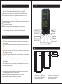
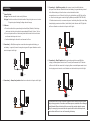
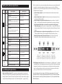
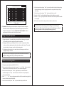
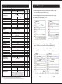
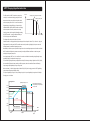
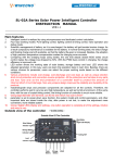
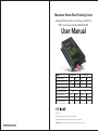
Maximum Power Point Tracking Series
Intelligent Wireless all-in-one with step-up LED driver
MPPT solar charge controller MPC2415/2410
User Manual
MPC2410
Model
MPC2415
Battery voltage
12V
24V
12V
24V
Max.solar input power
130W
260W
200W
400W
Max.solar input voltage
17V~60V
34V~60V 17V~60V 34V~60V
<75V
Max.Voc of solar panel
Max.charging current
15A
10A
Max.LED power
60W
120W
80W
160W
The No. Of LED in series
5~18
10~18
5~18
10~18
LED output voltage
15V~60V
30V~60V 15V~60V 30V~60V
Dear users:
Thank you very much for choosing our products!
Please read the manual carefully before using our controllers.
Material Code:1.1.24.01423
Version: 1.01
The above information is subject to change without prior notice.
Features
Faceplate
Support both lead acid(Gel included) and lithium battery both for 12V and 24V system.
Adopts MPPT charging method, which supports the Voc of solar panel≤75V.
With step-up constant current source for output, which can drive 18 LEDs in series.
Multi-crest MPPT tech, adapts to the solar panel which is under shadow or partly
damaged.
4 levels dimming design(including morning lighting).
IR remote control: for parameter setting, parameter reading and historical data checking.
Auto identify day/night.
Very low dormancy loss: 0.06W.
Protections: IP68, over charge/over discharge protection, reverse connection
protection, reverse charging protection, over load/over current protection, short circuit /
open circuit protection, over temperature protection, TVS lighting protection.
Brown/Load positive
IR receiver
Red/Battery positive
IR transmitter
Instructions
Black/Share negative
The solar panel voltage may exceeds human safety voltage, pls use insulating tools
while operation.
2.
Battery indicator
Temperature sensor
PV indicator
Pls wiring correctly, do not wrong wiring, reverse connection or it will be short circuit.
Though our controller have all the protections, but it will do harm to our controller and
your solar battery.
3.
Load indicator
Size
The wiring of the whole system will be varies, pls pay attention to insulation, wrap up
each wire after it’s connected.
4.
Φ3.5
Φ3.5
Our MPPT controller is designed for the VI curve of solar panel, it’s not suitable for
constant voltage DC power supply.
142
102
dissipated place.
88.33
114
74
5. Choose the wires which is of enough capacity, to avoid big loss on the wiring.
6. Our controller will emit heat during operation, so pls install it in ventilated and heat
24.47
1.
Blue/PV positive
7. Fully charged of the battery is very important, pls fully charge the battery once a monty,
or the battery will be damaged.
82.33
8. Please do not dip the controller into the corrosive liquid otherwise the controller will be
damaged and release harmful gas.
9. Because the battery stores lots of energy, do not allow the battery short circuit in any
case. We suggest tandem connect a fuse on the battery.
10. The battery may release combustible gas, please far away from the spark.
11. Ensure the children are far away from battery and controller.
12. Please abide by the battery manufacturer’s safety suggestion.
82.33
MPC2415 Dimension as below
MPC2410 Dimension as below
Overall dimensions:142x88.33x24.47(mm)
Overall dimensions:114x88.33x24.47(mm)
Installation dimensions:102x82.33(mm)
Installation dimensions:74x82.33(mm)
Installation aperture:Φ3.5(mm)
Installation aperture:Φ3.5(mm)
5. Connection③—Red/Battery positive: after connect correct the middle indicator
Installation
will open.The red indicator instead of the lead acid battery, the green indicatory instead
of the lithium battery, with two function can check whether the load is
1. Controller fixed:
1st type: Fixed the controller in the case by M3 screw.
2nd type: Fixed the controller in the holder inside of the pole by the screw or iron wire.
Pls protect against freezing ,flooding and wire damage.
2. Cable use:
connected correct or not:1.Press the "test" key, the load indicator and LED light will be
on. Press the test key again can test the light by different power(100%-70%-30%-0%).
2. If without remote control, can remove solar panel and waiting after light control delay
time(setting by remote control before, 1mini default), Load indicator and LED light both
will be on. Attention: use the electrical tape to hold it tight.
a. Pls use the cable which ampere density less than 4A/mm²; Besides, if the battery
cable more than 2m,pls calculate the ampere density( 8/length) A/mm², Unit: m.
b. Do not strip the insulation of the battery cable before connect to the controller to
avoid cause the battery short circuit.
c. Use the suitable length cable which can decrease the E-loss.
3. Connection①—Black/Share negative: connect the share negative with battery, pv
and battery’s negative; Connect the negative to ground if request. Attention: use the
electrical tape to hold it tight.
3
图C
6. Connection④—Blue/PV positive: Solar panel voltage might be exceed 36V(safe
voltage), attended prevent electric shock. The solar panel connected ok, PV indicator
will be on after 10s later means that in charging. Now can use the Ampere meter to test
1
1
1
the charging current is normal or not. Attention: use the electrical tape to hold it tight.
图A
4. Connection②—Brown/Load positive: Attention: use the electrical tape to hold it tight.
4
图D
The mentioned above are the connection suggestion which consider about the system
safety and easy operation. If use other connection sequence, controller will not damage
2
but will showed different indication. When connected pls consider about the system
safety. For example, just connected the solar panel under the lead acid battery mode,
three indicator will be on in turn until connecting the battery.
图B
2. MPC controller with four section working mode, the 4th section is morning light time and
Working Status Indication Specification
each section can be adjust range from 0 to 15hours, power is from 0% to 100%, the
adjustment unit is 1hours and 10% power. This four section can be setting and combine
Serial
Number
Indicating Status
Normally on.
Slow flash.
(light for 1s,off for 1s,the cycle is 2s)
Single flash.
State of charge
Charge at Max. Power.
indication
Fast flash.
Float charging.
③ Light is working at all night but delay 2hours start: the first section”2hours,0%
Equalizing charge.
④ Light is open but delay 2hours start and then running 5hours and light again
and morning light time is 0hour.
power”, other sections the working time setting should be more than night length.
2hours before dawn : the first section”2hours,0% power”, 2nd and 3rd sections the
Double flash.
total working time setting is 5hours and morning light section(the 4th section) setting
Current limited charging.
reclose for 1.7s,the cycle is 2s)
Off
Normally on.
Battery
Slow flash.
indication
(light for 1s, off for 1s, the cycle is 2s)
Fast flash.
(light for 0.1s, off for 0.1s, the cycle is 0.2s)
Normally on.
Slow flash.
(light for 1s, off for 1s, the cycle is 2s)
Fast flash.
(light for 0.1s, off for 0.1s, the cycle is 0.2s)
Other
indication
2hours.
⑤ Light is working 4hours at night and morning light 2hours: the first three section
Solar panel voltage too low can
not charging.
Red light: Lead acid battery; Green light: lithium battery
indication
night length.
② Light is working 5hours at night: the first three section total working time is 5hours
(light for 0.1s,off for 0.1s,the cycle is 0.2s)
(light for 0.1s,off for 0.1s,reopen for 0.1s,
Load
① Light is working all night: four section working time should be setting more than
Boost charging.
(light for 0.1s,off for 1.9s,the cycle is 2s)
Charging
to different mode, for example:
total working time is 4hours and morning light time(the 4th section) is 2hours.
⑥ Moring light mode working 3hours before dawn : the first three section total
working time is 0hour and morning light time(the 4th section) is 3hours.
The battery voltage is normal.
The battery is over discharged.
100
70
50
30
The battery is over voltage.
Light
Off
Load open
Open circuit.(Load)
Short circuit.(Load)
Off
Load closed
Three indicator were opened in turn and
System only connect with solar
circle.
panel.
Three indicator were closed.
Without power or in sleeping mode.
Working
Time 1
Parameter:0~15h
Default value:4h
Parameter:0~100%
Default value:100%
Working
Time 2
Parameter:0~15h
Default value:0h
Parameter:0~100%
Default value:70%
Working
Time 3
Parameter:0~15h
Default value:4h
Parameter:0~100%
Default value:50%
Morning Light
Time 3
Parameter:0~15h
Default value:0h
Parameter:0~100%
Default value:30%
3. LED Intelligent Power Control:While customer open the “Intelligent power” mode, the
controller will enter to the intelligent power control mode, The LED load power will adjust
automatically according to the battery power. The working time and load power preset
Load Working Mode Specification
1. Light control/Close the load: MPC controller can recognize night and open the load ;
And it also can recognize day and closed the light even though it does not reach to the
before is still valid; system will compare with the automatically power and the preset
power, and choose the smaller one as the load output power.
For example: when the battery power is 50%,intelligent power mode calculate the
load power is 60%,if customer preset the load power as 100%,the system will choose
working time set in advance. Solar panel voltage less than light control voltage recognize
60% as load power. If customer preset the load power as 20%, the system will choose
as night. Solar panel voltage more than “light control voltage+1V” recognize as day.
20% as load power.
Load power
Load power & Batter y capacity
6. Aim at the controller and press ”State” key to read the historical data including running
110%
100%
90%
80%
70%
60%
50%
40%
30%
20%
10%
0%
date,over-discharging times,full charging times and the change data of battery voltage
within 7days.
7. Aim at the controller and press ”Test” key to test the light is on or off.
8. Press the ”BackL” key, the backlight will be open which suitable to use at night.
9. Press the ” Light” key, the light in front of the remote control will be open which suitable
0%
%
5%
%
10
15
%
%
%
%
20
25
30
%
%
%
%
35
40
45
50
55
%
%
60
65
%
%
%
70
75
80
%
%
%
85
90
95
10
0%
to use at night.
10. The remote control will enter sleep mode when without use after 1mins.
Battery capacity
4. Test mode: Use for testing no matter at night or on day time. Press the test key,the
LED indicator and the LED light will open, press the test key again the power of the
led light will change with four sections:100%
70%
30%
0%
100%…Without
any operation about 1min,controller will exit the test mode.
Energy saving and sleep mode
1. Energy saving mode:if no need lighting, controller will enter the energy saving mode.
The second days will exit the energy saving mode after sunshine.
2. Sleeping mode: Battery over-discharge 1mni later or in short circuit protection 6times
continuous will enter sleeping mode and the three indicators will be closed. The second
day when battery is charging ,controller will exit sleeping mode.
3. In sleeping mode, remote control can awake the controller temporary and will enter
sleeping mode again 1min later.
The system has been running many days and found that three indicator closed, it
might be in sleeping mode can try to awake by remote control.
Remote control setting declare
(Setting description pls refer to the remote control specification)
1. The remote control model(Use for MPC):SR-CU-M
2. Press any key to start the remote control. Long press”+” and “Light” 3s can lock/unlock
the remote control;When remote control lock, can not read and setting data.
3. Aim at the controller and press ”Param” key(parameter) can read the data from
controller. A long voice “beep” means that success. Three times “beep-beep-beep”
voice means that failure.
4. Press”+”,”-”,”Set” key can setting parameter. Remark:Pls choose the battery type firstly
because the data setting will be different.
5. Aim at the controller and press ”Send” key to send and setting controller data.
The remote control can keep two group data including Lead-acid battery and
Lithium battery. When change the battery type, the data will change according to
the battery type what u choose, pls setting the battery type firstly.
Parameter
Typical efficiency diagram
Parameter Name
Value
Model
MPC2410
Supported battery
MPC2415
Lead acid battery(gel included) and lithium battery
Battery voltage
12V
12V
24V
Battery voltage range
24V
Solar panel power
Solar input voltage
Max load power
LED in series(S)
260W
34V~60V
200W
17V~60V
400W
34V~60V
60W
5~18
120W
10~18
80W
5~18
160W
10~18
15V~60V
30V~60V
15V~60V
30V~60V
≤95%
≤97%
≤95%
≤97%
No-load loss
≤0.55W/normally operation,≤0.32W/energy saving mode,
≤0.06W/sleep mode
Voc of solar panel
<75V
>99%
15.5V;×2/24V
Limited Charge voltage
Float charge voltage
Temperature compansation
Charging prohibited under 0℃
Charging method
Over charge voltage
Over-charge recover voltage
For lithium
batter y
Boost charge time
For lead acid batter y
Over voltage protection
Boost charge voltage
13.3V battery,PV peak voltage 17V,34V,60V) (Pic 1)
Lithium
battery only
2. Controller energy conversion efficiency(Conditions: MPC2415,MPPT charging,
130W
17V~60V
MPPT tracking efficiency
17.0V;×2/24V
(Equalizing charge voltage + 0.4V);×2/24V(25℃)
1 Hour
30 Days
7.5V~15.5V;×2/24V(25℃)
4 Hour
7.5V~15.5V;×2/24V(25℃)
√
<Yes, No>
13.8V
√
Invalid setting
<0、1>
7.5V~15.5V;×2/24V
√
14.6V
7.5V~15.5V;×2/24V
√
13.6V
√
11.0V
√
900mA
7.5V~15.5V;×2/24V
7.5V~15.5V;×2/24V
output ,13.3V battery,5 pcs /10 pcs/18pcs LEDs in series,80Wmax) (Pic 3)
4. Controller energy conversion efficiency(Conditions: MPC2415,constant current
output ,26.6V battery, 10 pcs/18pcs LEDs in series,160Wmax) (Pic 4)
±3% or ±30mA
Light control voltage
5V~15V;×2/24V
√
10V
Light open time delay
1~50min
√
1min
1min
-40℃ ~ +60℃;
Light close time delay
Working temperature
Internal overtemperature protection
3. Controller energy conversion efficiency(Conditions: MPC2415,constant current
12.6V
70~5600 mA
70~4200 mA
Output current accuracy
(Pic 2)
14.4V
No
Over-discharge recover voltage
Output current range
(Pic 1)
√
-3.0mV/℃/2V
Over-discharge voltage
70℃~85℃decrease the power step by step, when over 85℃,
load or charing will be off.
390g
490g
Product dimension
114×88.3×24.5(mm)
142×88.3×24.5(mm)
Installation dimension
74×82.3(mm) , Φ3.5
102×82.3(mm),Φ3.5
Protection
1.IP68 degree;2. PV and Battery reverse connection;4. internal
overheat;5.PV over voltage, short circuit; 6.charge,discharge
over load; 7.Anti converse charge at night;8.TVS protection to
PV. 9. Load short circuit, open circuit ;10. Battery open circuit
Weight
1. Controller energy conversion efficiency (Conditions: MPC2415,MPPT charging,
26.6V battery,PV peak voltage 34V,60V) (Pic 2)
Circuit efficiency
Output voltage range
Equalizing charge interval
√
15A
10A
Limited charge current
Equalizing charge time
Default
value
7V~36V
Charge current
Equalizing charge voltage
Adjustability
Remark: 1.The real mini output voltage is higher than currently battery voltage about 1V.
2. The real mini output voltage is limited by mini output current 70mA and mini output voltage.
(Pic 3)
(Pic 4)
The MPPT tracing efficiency test (under the shaded condition)
1. There’s shadow in the middle of PV module, the tracing efficiency is 96.34%.
3. Simulate tree shade covered PV module, the tracing efficiency is 99.88%
2. There’s shadow at the top left corner of PV module, the tracing efficiency is 99.70%.
4. There’s wide-range shadow covered PV module, the tracing efficiency is 98.41%
MPPT Charging Algorithm Instruction
The full name of the MPPT is maximum power point
Current
Working point of the general controller
tracking. It is an advanced charging way which could
Maximum power point
detect the real-time power of the solar panel and the
maximum power point of the I-V curve that makes the
highest battery charging efficiency. Contrast with the
traditional PWM controller, MPPT controller could play a
maximum power of the solar panel so that a larger
charging current could be supplied. Generally speaking,
the MPPT controller’s energy utilization efficiency is
12.0V
17.5V
22.0V
Voltage
15%~20% higher than PWM controller.
The voltage of the solar panel is about 12V when
General controller is charging while the highest voltage of the solar panel is about 17V, so it doesn’t play the
largest power of the solar panel. MPPT controller overcome this problem by adjusting the input current and
voltage constantly to realize the largest input power.
Meanwhile, the maximum power point will change due to the surrounding temperature and sunshine condition.
MPPT controller will adjust the parameter constantly according to different conditions to make the system
working in the largest power point.
As a charging stage, MPPT can’t be used alone. It must be combined with ascending charge, floating charge,
equalizing charge to complete the battery charge.
The controller will judge the battery voltage before working. If the battery voltage is higher than 13.2V(*2/24V),
the controller will judge the battery working as full charge state, then the controller will enter into floating
charge stage, except equalizing charge or charge hint.
When the battery’s initial charging voltage is under13.2V (*2/24V), the charging process is: MPPT-equalizing
charge-boost voltage charge-floating charge.
The span of equalizing charge is 1 hour, ascending charge is 4 hour, and equalizing charge interval is 30 days.
Charging curve is as below:
Voltage/Current
Equalizing charging 1 hour
14.6V
14.4V
Battery voltage(fully charged)
Battery voltage(not fully charged)
Charge current
Ascending charging 4 hours
13.8V
13.2V
Floating charging till night
Voltage
12.0V
Current
1.5A/
100AH
MPPT charging stage
Dawn
Equalizing/ascending
Floating charging stage
charging stage
Daytime
Night
Time