1
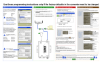
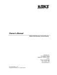
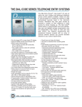
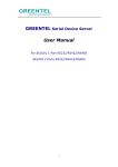
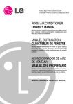
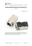
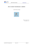
Use these programming instructions only if the factory defaults in the converter need to be changed
A Programming the 1830-188 TCP/IP Converter (only if necessary)
B Accessing the 1830-188 Menus
1.
C Changing 1830-188 Settings
Open any browser and type in the address of the
CONVERTER: http://192.168.1.40
1.
We recommend using a separate router to make the connection to the 1830-188 so that it is not necessary to change any of the owner’s router setup details.
2.
Login (wired or wirelessly) to the setup router with a computer. The IP address for this router must be 192.168.1.1.
3.
Using the network cable supplied with the 1830-185 kit, plug one end into the setup router and the other into the CONVERTER.
Mozilla Firefox
4.
Power the CONVERTER with the supplied power supply.
File
5.
Make any necessary changes to the 1830-188 per instructions in Part B.
Port 0 Settings
The current settings for port 0 may be changed using the form below.
The user Log In window for the CONVERTER will appear.
Edit
Current Status
Local IP Config
View
History
Bookmarks
Tools
Help
RS232
Baud Rate:
RS485
Data Size:
Web to Serial
http://192.168.1.40
Misc Config
Reboot
Remove the network cable from the setup router when completed, and plug it into the owner’s router.
Modem
N.I.D.
Router
1
2
3
4
Owner’s Router
xxx.xxx.xxx.xxx
Remote Port Number:
User name: admin
Temporary Setup Router (provided by installer)
Work Mode:
TCP Server detail:
*****
Login
Remote Server Addr:
Reset
192.168.1.1
1
Modem
N.I.D.
Router
1
2
3
2
4
Enter the User name and pass word:
User name:
admin
Pass word:
admin
bps
bit
None
1
bit
Hardware
1040
23
TCP Server
None
default
type
192.168.0.201
[N/A]
seconds (< 256, 0 for no timeout)
UART packet Time:
10
ms (< 256)
UART packet length:
512
chars (< = 1460, 0 for no use)
Sync Baudrete (RF2217 similar):
Save
The Status and Configuration window will appear.
Cancel
Notes:
Baud Rate can only be set to 9600 or 19200. These are the only two speeds that 1830 Series boards will run at.
Leave all other settings as shown when the converter is used in the Server Mode.
Status and Configuration
3
8
0
Timeout:
2.
4
Flow Control and RS485:
Local Port Number:
Please login:
6
Pass word:
Current Status
Local IP Config
RS232
RS485
Web to Serial
Misc Config
Ethernet
10M/100M
USR-TCP232-410
3004
Current IP Address:
MAC Address:
Run Time:
192.168.1.40
d8-b0-4c-00-8d-55
0day: 0hour: 4min
TX Count(ETH):
RX Count(ETH):
IP Address Selection
Current Status
Local IP Config
0/0/0 bytes
0/0/0 bytes
RS232
RS485
Web to Serial
Static IP
192
168
1
40
Submask:
255
255
255
0
Gateway:
192
168
1
Save
1
Cancel
Reboot
Notes:
These are the default settings and should be left alone. If the static IP address
is changed, the module will lose communication with the PC. You will need to
log into the module at the new IP address using the browser.
You can access settings of the CONVERTER
by using the
menu at the left in the Status and Configuration screen. Only
selections 1, 2 and 6 apply to this module.
1
2
3
4
5
6
A(+) B(-)
RS485
IP type:
Static IP:
Misc Config
C
RS-232 & 485 To Ethernet
RS-232
Module Name:
Firmware Revision:
Reload Defaults
Reboot
Network
Pwr
DC 5-18V
6.
Parity:
Stop Bits:
19200
1830 Series
Controller
RS232
Terminals
It is highly recommended that you DO NOT change the password
on the authentication screen. DoorKing will not be able to assist
you if you don’t know your ID or password. This system status
window is informational and there’s no need to change anything
here.
Reset:
1. Remove power from module.
2. Press the Reload button and apply power.
3. Hold the reload button for 3 seconds, then release.
Module is now reset. TCP IP address will be 192.168.1.40. User
name and password will be admin. All other settings will need to
be configured.
Using a setup router
menus.
1 eliminates the need to login into the owner’s router and changing the IP address there to access the TCP/IP adapter
Set the IP address on the setup router to 192.168.1.1, otherwise you will not be able to communicate with the TCP/IP adapter.
Don’t forget to plug the network cable from the TCP/IP adapter
3 into the owner’s router 6 once programming is completed.
INSTRUCTIONS FOR 1830-185 TCP/IP MANUAL MODE to RS-232 CONVERTER KIT
Connection via INTERNET
General Information
System IP Address
Network
Communication
Model Number
Area Codes
Dial
First, then
Modem
RS232
Diagnostics
IM Server Modem
IM Server Client
DKS Cellular
Network
Network selected in Remote
Account Manager Software
V6.3.g or higher.
Use these instructions when using the TCP/IP adapter, part number 1830-185. This device is a manual
setup (no subscription required). For Plug and Play setup (no manual setup required) use TCP/IP adapter
part number 1830-186 (IM Server Client subscription service required).
System IP Address
Communication
Model Number
Area Codes
You can use the 1830-185 Converter Kit with the following DKS Systems:
1830 Series Telephone Entry and Access Control Systems (1833, 1834, 1835, 1837, 1838).
Dial
Refer to these instruction manuals for additional information:
P/N 1835-065 Telephone Entry Systems Installation Manual
P/N 1838-065 Access Controller Installation Manual
P/N 1835-066 Remote Account Manager Software User Manual
First, then
Network
Modem
RS232
Diagnostics
IM Server Modem
IM Server Client
DKS Cellular
Network
Network selected in Remote
Account Manager Software
V6.3.g or higher.
Connect Converter to 1830 Series Circuit Board RS-232 Terminals
LAN
Internet
Ethernet
10M/100M
Note:
RS-232 wire runs are limited to 100
feet maximum. If greater distance
is needed, use RS232 to RS422
Extender Kit, P/N 1830-190 (4000
Feet maximum distance).
Reload Defaults
Network
Pwr
DC 5-18V
Network
Interface
Device
Connection via LAN
Network
Interface
Device
Modem
N.I.D.
LAN
1
Router
2
3
Router
2
3
4
DB - 25
PINS
1
3
2
Transmit Data
2
2
3
Receive Data
3
7
4
Request to Send
4
8
5
Clear to Send
5
5
7
Signal Ground - Shell
RS-232 & 485 To Ethernet
Reload Defaults
Network
Pwr
DC 5-18V
6
Ethernet
10M/100M
RS-232
P/N 1830-181 Rev C 7-15
RS-232
Not Used
A(+) B(-)
RS485
Shield
+
Green
5
Red
3
9
A(+) B(-)
RS485
Black
2
1
6
8
7
Brown White
RS-232 Cable
P/N 1818-040
(6 Ft. Cable)
RS232 wire runs
limited to 100 Ft.
Maximum. See
note above.
FUNCTION
RED
BLACK
WHITE
BROWN
GREEN
SHIELD
1
2
3
4
5
6
RS-232 wire terminal
on telephone entry /
access control system
circuit board
Ethernet
10M/100M
Reload Defaults
1
DB - 9
PINS
RS-232 & 485 To Ethernet
Modem
N.I.D.
LAN
BOARD
TERMINALS
Network
Pwr
DC 5-18V
Network
Interface
Device
RS-232 & 485 To Ethernet
Internet
RS-232
A(+) B(-)
RS485
4