1
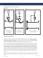
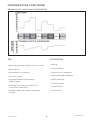
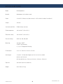
KAM® OID™
OPTICAL INTERFACE DETECTOR
User Manual
OIDMANUAL-0614
PTB 08 ATEX 1027
TEL +1 713 784 0000
FAX +1 713 784 0001
Email [email protected]
KAM CONTROLS, INC.
3939 Ann Arbor Drive
Houston, Texas 77063 USA
www.KAM.com
An ISO 9001 certified company
TA B L E O F C O N T E N T S
SECTIONTITLEPAGE
1 Introduction 2
•Available Models and Mounting Options
2
•Theory of Operation
2
•Features 3
•Applications
3
2 Specifications4
•Specifications
4
•Dimensional Drawings 5
3 Installation7
•Sensor location 7
•Do's and Dont's 8
•Main Line 10
•Removal 13
•Analyzer Loop
14
•Wiring
15
•Connecting the OID
16
4
Field Calibration
17
5Maintenance19
CAUTION:
When installing the OID™ sensor in a pipeline containing petroleum products,
petro-chemicals, waste waters with the presence of pressure & temperature, and high-pressure
steam refer to the Pipeline Operators’ “Health, Safety and Environmental Policy Procedures” to
ensure safe installation.
KAM CONTROLS, INC. reserves the right to make changes to this document without notice.
OIDMANUAL 0614
1
KAM CONTROLS, INC.
INTRODUCTION
AVAILABLE MODELS and MOUNTING
OPTIONS
FIG.
FIG.
Fullopening
Ball
Valve
Rectractable OID™
on a main pipe, with
2", 3", or 4" flanged
seal housing
FIG.
Fullopening
Ball
Valve
Rectractable OID™
on a main pipe, with
2" MNPT seal housing
OID™ FT Flow Through
on a densitometer loop
with ¾" or 1" MNPT
THEORY OF OPERATION
The KAM® OID™ Optical Interface Detector has been the preferred sensor for interface detection between
refined products since its inception in 1995. Literally like eyes in the pipe, it provides accurate, real-time
data on product interface and quality. That data allows operators to monitor interface in real time, making
the most advantageous cut and significantly reducing product downgrade and/or transmix.
The simplicity of design and quality of engineering employed in the OID™ sensor mean there are no moving
parts. The OID™ is comprised of an optical probe inserted into the fluid/flow and connected via fiber optic
cable to the related transmit and receive electronics which are housed within an explosion-proof enclosure
on the atmospheric end of the sensor. During operation, light from the light source in the explosion-proof
enclosure travels via the fiber optics cable to the process fluid. Unabsorbed light returns via the fiber optics
cable to a photodetector in the explosion-proof enclosure. The resulting information regarding the absorption,
fluorescence, and refractive properties of the fluid is then turned into an analog signal or "optical signature."
Measurement is fully automatic without the need for operator intervention or supervision. The output signal
can be sent to a SCADA, PLCs, or to a Central Control Room for logging or display on chart recorders or
monitors.
The KAM® OID™ sensor can be installed in an analyzer loop or in the main line. Because main-line models are
mounted through a full-opening ball valve, you can insert or retract the probe without having to ever drain the
pipe.
OIDMANUAL 0614
2
KAM CONTROLS, INC.
INTRODUCTION CONTINUED
FIG. 1-4 KAM® OID™ AND API GRAVITY/DENSITOMETER
FEA-
APPLICATIONS
• Detects the interface of specialty fuels such as ULSD
• Batching
• No moving parts
• Interface detection
• Measurement is fully automatic
• Product transmix management
• Lens cleans in place
• Product downgrade management
• Insertable/retractable and flow-through
models available
• Pipeline automation
• Chemicals interface
• Output signal can be sent to a SCADA, PLC’s,
or to a Central Control Room
• Clear oil interface
• Quality control
• Insertable model installs without having to drain
the pipe
OIDMANUAL 0614
3
KAM CONTROLS, INC.
S P E C I F I C AT I O N S
Media:Refined products
Material:
Wetted parts–316 stainless steel
Power: 12–24 VDC 15 Watts max (Max current is 1275 mA @ 12V and 637 mA @ 24V)
Output:4-20 mA
Communication Port:
RS485 (factory use only)
Fluid temperature:
-40º to 160º F (-40º to 70º C)
Electronics temp.: -40º to 160º F (-40º to 70º C)
Pressure ratings: ANSI 150, 300, 600, 900
Mounting:
3/4" and 1" MNPT
2" MNPT Seal Housing
2", 3", or 4" Flanged Seal Housing
EX enclosure: 3" x 6" x 3" (76 mm x 152 mm x 76 mm)
Shaft length:
12" to 60" – Off-the-shelf lengths are 24", 30", 36", 48", and 60"
(610 mm to 1524 mm)
(Off-the-shelf 610 mm, 762 mm, 914.4 mm, 1219 mm, 1524 mm)
Pipe size:
3/4" to 48" (20 mm to 1200 mm)
Weight: from 10 lbs. (4.5 kg)
OIDMANUAL 0614
4
KAM CONTROLS, INC.
L= 24" 30" 36" or 48" other sizes can be
S P E C I F I C AT I O N S C O N T I N U E D
DIMENSIONAL DRAWINGS
FIG. 2-1OID™ SENSOR with FLANGED
SL
C (Shaft Diameter)
E
Seal Housing
B
D
A
¾" FNPT
Shaft Length ± .5"
TABLE 2-2 FLANGE SIZE AND CLASS (SL)
300
150
900
600
"
INCHES
MM
INCHES
MM
INCHES
MM
INCHES
MM
2
8.40
213
8.50
216
8.90
226
9.40
240
3
8.60
218
8.75
222
9.15
232
9.40
240
4
8.60
218
8.90
226
9.40
240
9.65
245
TABLE 2-3 DIMENSIONS
INCHES
MM
A
1.443
37
B
1.25
32
C
1
25
D
4.53
115
E
7
178
OIDMANUAL 0614
Shaft Lengths are available in .5" (12.7
mm) increments.
Standard sizes are 24", 30", 36", 48",
and 60". (610 mm, 762 mm, 914.4 mm,
1219 mm, 1524 mm)
5
KAM CONTROLS, INC.
SPECIFICATIONS CONTINUED
FIG. 2-4 FLOW THROUGH OID™ for ANALYZER LOOP
F
E
D
C
B
G
A
¾" or 1"
MNPT
H
¾" FNPT
TABLE 2-5 ¾" MNPT DIMENINCHES
MM
TABLE 2-6 1" MNPT DIMENINCHES
MM
A
.3
8
A
.3
8
B
.5
13
B
.5
13
C
1.4
36
C
1.45
37
D
2.25
57
D
2.4
61
E
6.75
171
E
6.75
171
F
7
178
F
7
178
G
4.53
115
G
4.53
115
H
1.2
30
H
1.3
33
OIDMANUAL 0614
6
KAM CONTROLS, INC.
I N S TA L L AT I O N
LOCATION
For optimal batch detection, KAM CONTROLS recommends that you install the in-station OID™ sensor at the
first accessible pipeline location inside the terminal fence-line — upstream of the interface cut valve(s). This allows the operator ample time to open/close the cut valves prior to the arrival of the product interface.
KAM CONTROLS also strongly recommends that you utilize a preview (or out-station) OID™ sensor. This lets the
operator decide how to optimize each batch cut prior to actually making the batch cut at the in-station and gives
TERMINAL
FENCE
the operator more confidence
in their
decisions as well as the time to identify and resolve any issues that may
arise during a critical interface.
FIG. 3-1 RECOMMENDED OID™ LOCATIONS
TO TANK
OUT-STATION/PREVIEW
OID
TYPICALLY
1 - 2 MILES
(1.6–3.2km)
IN-STATION/CUT
OID
CUT VALVES
TO TANK
INCOMING
OID
TO TANK
TERMINAL FENCE LINE
PRIOR TO INSTALLATION
Remove all the protective packaging materials including the red cap placed at the tip of the sensor probe. Ensure that the OID™ sensor was not damaged during transit.
CAUTION: Do not stand the OID™ sensor on the probe end or allow the probe to hit the ground or any hard
surface under any circumstances. This will damage the lens, and the OID™ sensor will not work properly.
OIDMANUAL 0614
7
KAM CONTROLS, INC.
I N S TA L L AT I O N C O N T I N U E D
INSTALLATION DO’S AND
DO NOT install the
fast loop OID™
sensor in a straight
portion of pipe.
It needs to be
mounted off the
bend opposite the
pump.
P
P
FLOW
FLOW
FLOW
FLOW
P
FLOW
DO NOT install the
OID™
sensor with the
lens facing directly
into the flow. If
the product has
particulate
matter in the fluid,
like sand, this will
sandblast the lens
and could cause
premature failure.
P
FLOW
FLOW
FLOW
I
I
DO NOT attempt
to screw the OID™
sensor either in
or out by hand.
Always use a
1 1/4" or 1 3/8"
wrench on the
wrench flat below
the electronics
enclosure.
P
P
FLOW
FLOW
FLOW
FLOW
OIDMANUAL 0614
8
KAM CONTROLS, INC.
I N S TA L L AT I O N C O N T I N U E D
INSTALLATION DO’S AND
DO NOT use teflon
tape on the OID™
sensor threads. DO
use liquid thread
sealant.
DO install the
OID™ sensor with
a minimum of 8"
or 200mm between the lens and
the nearest flat
surface.
P
Minimum 8"
(20.3 cm)
FLOW
FLOW
DO install the
OID™ sensor with
a sun shade if the
electronics are
directly exposed to
sunlight.
P
OIDMANUAL 0614
9
KAM CONTROLS, INC.
I N S TA L L AT I O N C O N T I N U E D
PRIOR TO INSTALLATION
Remove all the protective packaging materials, and ensure that the OID™ sensor was not damaged during transit.
MAIN LINE INSTALLATION
The KAM® OID™ sensor should be installed
according to FIG. 3-2. KAM CONTROLS
recommends installing the OID™ sensor at a 2 or
10 o’clock position to ensure the tip of the probe
remains in the fluid. A full opening ball valve is
used to isolate the OID™ sensor from the pipeline
during installation or removal. The seal housing of
the OID™ sensor allows the optical probe to be
inserted and removed from the pipe under pressure
and flow conditions. It is the user’s responsibility to
ensure that the OID™ sensor is placed at the most
representative point within the flow profile. The
OID™ sensor should be inserted so that the tip of
the probe is located 1/4" above the inner wall of the
pipeline. This ensures that the probe is not
damaged when pigging the pipeline.
FIG. 3-2 KAM® OID™ INSTALLED ON A MAIN PIPE
Locking Collar
Seal Housing
Full-opening
Ball Valve
Socket Cap
Screw
NOTE: If line pressure exceeds 100 psi, use a KAM®
IT Insertion Tool when installing/removing
the KAM® OID™ sensor.
Prior to mounting the OID™ sensor on the
Full-opening Ball Valve, you must determine
the insertion length required.
FIG. 3-3
1. Lay the OID™ sensor on the ground or a table.
2. Loosen Socket Cap Screws on the locking
collar. This will allow the OID™ shaft to slide
through the seal housing.
3. Push the OID™ shaft though the seal housing
until the OID™ probe sits flush with the end of
the seal housing or seal housing flange. FIG.
3-3 and 3-4. (Remove red protection cap on the
tip of the probe if it has not been removed.)
Mark here
FIG. 3-4
4. Place a mark with a sharpie or a permanent
marker on the shaft at the edge of the locking
collar. (Do not use anything sharp to mark the
shaft as this will create grooves that will
damage the O-rings in the seal housing.)
OIDMANUAL 0614
Mark here
10
KAM CONTROLS, INC.
I N S TA L L AT I O N C O N T I N U E D
5. Pull shaft back until the probe is all the way in the seal housing and tighten the socket cap
screws on the locking collar. This will prevent the the OID™ shaft from sliding and the probe from getting damaged during mounting.
6. Measure the distance (D1) from the outside diameter of main pipe to the end of the connection where the OID™
sensor is going to be installed. FIG. 3-5.
FIG. 3-5
D1
D1
7.
Calculate the insertion distance for Flanged Seal Housing (If you have a MNPT Seal Housing, proceed to
step 9):
Total Insertion Distance (TID) = D1 + Pipe Wall Thickness + Seal Thickness -1/4"
Example for D1= 19", Pipe WT=3/8", and Seal Thickness is 1/8"
TID=19 + 3/8 + 1/8 – 1/4 or TID=19 + .375 + .125 – .25
TID= 19 1/4" or 19.25"
8. Use the calculated TID and mark a second line on the shaft, measuring from first mark. FIG. 3-6.
FIG. 3-6
First Mark
TID
Second Mark
9. Bolt or screw the OID™ sensor to the valve or designated installation location.
(KAM CONTROLS recommends using thread sealant and not Teflon tape for the threaded OID™). Skip to Step 12
(OID with Flanged Seal Housing only).
OIDMANUAL 0614
11
KAM CONTROLS, INC.
I N S TA L L AT I O N C O N T I N U E D
10. Calculate the Insertion distance for 2" MNPT Seal Housing:
TID cannot be calculated until the Seal Housing is screwed into place. If you have not already done so, please
screw your OID™ sensor into place now.
You must then measure the Threaded Depth (TD) into the Valve or connection in order to calculate TID. You
can do this by measuring the distance from the edge of the Valve or female connection to the top of the Seal
Housing body and subtracting that distance from 5.25". FIG. 3-7.
FIG. 3-7
Measuring points
For example:
If the measured distance from the top of the valve to the top of the seal housing
body is 4.75", you would calculate the threaded depth (TD) by subtracting 4.65" from 5.25".
(5.25 – 4.65=0.6) In this case the threaded depth TD would be .6".
You are now ready to calculate TID.
TID= (D1) + (Pipe Wall Thickness) – (TD) – (.25")
Example for D1=19", Pipe WT=3/8", and TD=.6"
TID=(19)+(.375)-(.6)-(.25)
TID=18.525"
11. Use the calculated TID and mark a second line on the shaft, measuring from first mark. FIG. 3-8.
FIG. 3-8
First mark
TID
Second mark
OIDMANUAL 0614
12
KAM CONTROLS, INC.
I N S TA L L AT I O N C O N T I N U E D
12. If you have an OID™ with a Flanged Seal Housing, you may now attach it to the valve on the pipeline.
13. Slowly open Full-opening Ball Valve and check for leaks.
14. Loosen Socket Head Screw on the Locking Collar.
15. Push the OID™ in until the Second Mark is at the top edge of the Locking Collar. FIG. 3-9.
FIG. 3-9
Second Mark
10. Re-tighten the Socket Cap Screws.
11. Tighten the Hex Nuts on the top of the Locking Collar one half turn. These nuts should
never be over tightened. Their major function is to apply light pressure on the chevron packing to
ensure a seal between the seal housing body and the insertion shaft.
REMOVING THE OID™ SENSOR
1.
To remove the OID™ sensor, first disconnect all
electrical connections to the OID™ enclosure.
2.
Make sure that the line pressure is below 100 psi.
Then, slowly and with caution loosen the Socket
Cap Screws on the Lock Down Collar.
FIG. 3-10
Socket Cap Screws
NOTE: Once the Socket Cap Screws have been
loosened, the OID™ shaft may push out from the
line. If pressure in the line is above 100 psi, it may
do so with enough force to cause bodily injury or
damage to the instrument.
3. Slide the OID™ sensor upward until it stops and the
probe rests inside the seal housing. FIG. 3-10.
4.
Next, close the Full-opening Ball Valve tightly. The
OID™ sensor may now be unbolted from the system.
OIDMANUAL 0614
13
KAM CONTROLS, INC.
I N S TA L L AT I O N C O N T I N U E D
ANALYZER LOOP INSTALLATION
KAM CONTROLS recommends this installation for 3/4" & 1" MNPT OID™ sensors.
We recommend using thread sealant and not teflon tape for the OID™ sensor threads.
CAUTION: DO NOT USE THE ENCLOSURE TO TIGHTEN OR LOOSEN THE OID. THIS CAN CAUSE THE PROBE TO
COME UNDONE AND THE FIBER CABLE TO BREAK. Please refer to “Do’s and Don’ts” on pages 8-9.
KAM 3/4" and 1" MNPT OID™ sensors should be
installed according to FIG. 3-10. The OID™ sensor should be installed in an analyzer loop in such a
fashion that the flow sweeps across the probe lens
rather than rushing directly at the probe. The reason
for this is to:
1) obtain a credible reading of the product
pipeline interface
2) keep the lens of the probe clean and abrasion
free. If the OID™ is installed with the product
rushing directly at the probe, particles in the pipeline
can scratch the lens causing abrasions and resulting
in a non-credible reading. FIG. 3-11
Flow
P
You do not need to measure for insertion distance
on the fast loop models.
Pump
Flow
OIDMANUAL 0614
14
KAM CONTROLS, INC.
I N S TA L L AT I O N C O N T I N U E D
WIRING
FIG. 3-12
OFFSET
GAIN
Kam
Controls
Incorporated
OFF
3939 Ann Arbor Drive
Houston, Tx 77063
Tel + 1 713 784 0000
Fax + 1 713 784 0000
E-mail [email protected]
www.Kam.com
ON
4-20mA (+)
4-20mA RTN
CHS
RS485 OUT +
RS485 OUT –
RS485 IN –
RS485 IN +
V+
GND
INTENSITY
P5
PMT
GAIN
POWER
OUT-
V (+)
GND
4-20 mA (–) 4-20 mA (+)
Current output, source powered
COMMUNICATION INTERFACE (factory
use only)
RS485 OUT (+) Communication port
RS485 OUT (–)
RS485 IN (–)
RS485 IN (+)
OIDMANUAL 0614
CAUTION: When electronics enclosure is open, be extremely careful to avoid any contact with interior fiber
optic connections. Failure to do so could result in the OID
malfunctioning.
15
KAM CONTROLS, INC.
I N S TA L L AT I O N C O N T I N U E D
CONNECTING THE OID
1.
Proper Grounding of the OID™ sensor.
Grounding the OID™ sensor through the 4-20 mA signal out and power lines is not adequate to protect the OID™
sensor against power surges. To ground the OID™ sensor, connect the chassis ground on the OID™ board (labeled CHS on the OID™ Terminal
Block. FIG. 3-13) to the green grounding screw on the OID™ explosion-proof box using 16 AWG braided wire. Insure that the box is connected to Earth ground either through the pipeline or appropriate low-impedance buried
grounding structure.
NOTE: CHS is isolated from GND. Grounding CHS to pipeline through the grounding screw will not short OID™
GND to the pipeline.
2. To connect the power for the OID™ sensor, first check both wires from the source for polarity and
voltage, then label appropriately.*
3. Connect positive wire to V (+). FIG. 3-13.
4. Connect negative wire to GND on TB (Terminal Block).** FIG. 3-13.
5. Check voltage and polarity at TB, then turn OID on.
FIG. 3-13
ON/OFF Switch
ON
OFF
4-20mA RTN
Chassis Ground
CHS
3939 Ann Arbor Drive
Houston, Tx 77063
Tel + 1 713 784 0000
Fax + 1 713 784 0000
E-mail [email protected]
www.Kam.com
Kam
Controls
Incorporated
OFFSET
GAIN
4-20mA (+)
RS485 OUT +
RS485 OUT –
RS485 IN –
RS485 IN +
V+
Power Supply
P5
GND
PMT
GAIN
INTENSITY
EXTERNAL FUSES: MAXIMUM CURRENT LOOP RESISTANCE:
Power Amp slow fuse, Current loop 750 mA
500 Ohm
*Recommended Wire: Shielded twisted pair wire is recommended for both power and signal.
**WARNING: Connecting a power source to the 4-20 mA ports on the TB will damage the OID Power Supply Board
and result in failure of the unit.
OIDMANUAL 0614
16
KAM CONTROLS, INC.
F I E L D C A L I B R AT I O N
PRIOR TO ANY CALIBRATION, MAKE SURE POWER SWITCH IS ON
The KAM® OID™ sensor is factory calibrated at the time of shipment for user-specific, product-interface
requirements. However, field calibration may be required to fine-tune the instrument for increased or decreased sensitivity in specific applications.
INCREASE SENSITIVITY WHEN factory calibration is not sensitive enough to provide
adequate resolution for interface detection, and all readings are typically falling in the lower or
middle portion of the KAM® OID™ output range. Increasing sensitivity elevates the output
range to provide greater interface resolution.
DECREASE SENSITIVITY WHEN some products exceed the maximum reading of
the pre-calibrated settings. Products that exceed the pre-set calibration readings will
produce an off-scale reading exceeding 20mA. Decreasing sensitivity lowers the output
range of the KAM® OID™ sensor to allow all readings to fall within the 4-20 mA output ranges.
Caution: When multiple KAM® OID™ sensors are being used on the same system, each sensor should be
calibrated equally. If special calibration is applied to one unit, its output will vary from those of other units
measuring or monitoring like products.
The calibration procedure consists of increasing the gain or reducing the gain as needed to increase
or reduce sensitivity.
LED light output settings are pre-set at the factory and should not be adjusted.
REQUIRED TOOLS: VOLT METER, SMALL FLAT-HEAD SCREWDRIVER
CHANGING THE HIGH END OF OUTPUT RANGE
1.
Determine which product produces the highest current output.
2. Connect a volt meter across 4-20 mA terminals. When the highest output product is flowing, increase the
gain by turning GAIN (FIG. 4-1) counterclockwise or decrease by turning clockwise. As you are turning, look at
your volt meter and stop when it reads 18.4 mA or 80% of scale.
CHANGING THE LOW END
In most cases, products with the minimum current output are clear and readings will be consistent with factory
calibration. Only recalibrate the low end of the range in situations when there will be no clear product in the
pipeline.
1.
Determine which product produces the lowest current output.
2. Connect a volt meter across 4-20 mA terminals. When the lowest output product is flowing, increase or decrease the gain by turning OFFSET. As you are turning OFFSET, look at your volt meter and stop when it reads
7.2 mA or 20% of scale. SEE FIG. 4-1. Once the low end of the output range has been reset, output sensitivity
can be further refined by resetting the high end of the output range again.
FOR ALL OTHER TYPES OF ADJUSTMENTS CALL KAM CONTROLS, INC. +1 713 784 0000.
OIDMANUAL 0614
17
KAM CONTROLS, INC.
F I E L D C A L I B R AT I O N C O N T I N U E D
FIG. 4-1
OFF
ON
CHS
3939 Ann Arbor Drive
Houston, Tx 77063
Tel + 1 713 784 0000
Fax + 1 713 784 0000
E-mail [email protected]
www.Kam.com
RS485 OUT +
RS485 OUT –
RS485 IN –
RS485 IN +
V+
GND
P5
Kam
Controls
Incorporated
Minimum Output
Range Adjustment
OFFSET
GAIN
4-20mA (+)
4-20mA RTN
PMT
GAIN
Maximum Output
Range Adjustment
INTENSITY
OIDMANUAL 0614
18
KAM CONTROLS, INC.
MAINTENANCE
CLEANING AND INSPECTION
Under normal operation, the KAM OID should not require cleaning, unless pipeline usage is limited to a small number of products. Gasoline products or jet fuel in the pipeline will clean the OID without removal.
To remove any oil residues for visual inspection use a clean cloth with oil solvent or part washer.
Preferred solvents include, any petroleum solvent such as mineral spirits, xylene, toluene, gasoline, or diesel. Do not
use WD40 or other chemicals.
If you have a question regarding cleaning solvents, please contact KAM CONTROLS directly at
+1 713 784-0000, or email: [email protected]
TROUBLESHOOTING
If there is no signal output from the OID, please follow the steps below.
1. Please double check that the instrument is switched on. Fig. 5-1.
FIG. 5-1
LED5
LED3
ON/OFF SWITCH
LED5
OFF
ON
4-20mA RTN
CHS
3939 Ann Arbor Drive
Houston, Tx 77063
Tel + 1 713 784 0000
Fax + 1 713 784 0000
E-mail [email protected]
www.Kam.com
RS485 OUT +
RS485 OUT –
RS485 IN –
RS485 IN +
V+
GND
P5
Kam
Controls
Incorporated
OFFSET
LED4
LED3
4-20mA (+)
PMT
GAIN
INTENSITY
LED4
2. If the instrument is switched on and LED5 (Fig. 5-1) is NOT illuminated, it indicates a problem with the power
source: check the voltage input and polarity.
3. If LED5 is illuminated, source voltage and polarity should be correct.
OIDMANUAL 0614
19
KAM CONTROLS, INC.
MAINTENANCE CONTINUED
4. LED3 and LED4 (Fig. 5-1) should both be illuminated when the power switch on the instrument is in the ON
position. If LED5 is illuminated, the power switch is ON, and either LED3 or LED4 is off, this indicates that the
power supply on the OID is either damaged or there is a short in one of the circuits. In this case, the boards will have
to repaired or replaced. Please contact KAM CONTROLS at +1 713 784 0000 for spare or replacement boards and/or
to arrange for repair.
5. If LED5, LED3, LED4 and the power switch are all on, and there is still no signal out, this indicates that there may
be a short in the 4-20 mA circuit. In this case, the boards will have to repaired or replaced. Please contact KAM CONTROLS at +1 713 784 0000 for spare or replacement boards and/or to arrange for repair.
For all other issues, please contact KAM CONTROLS at +1 713 784 0000.
OIDMANUAL 0614
20
KAM CONTROLS, INC.