1
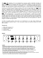
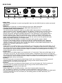
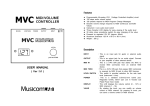
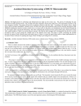
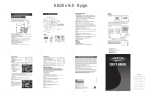
MIDI SWITCHER
Z-11
Operator´s Manual
Please, first read this manual carefully!
The
MIDI Switcher Z-11 was designed for accessing specific switchable functions of
amps (e.g.
"Ritchie Blackmore Signature", "Thunder 50", "Screamer", 19" rack units E530 or
E840) via MIDI that are switched via conventional 1/4" jack/plug-compatible footswitches.
Settings (e.g. Lead channel, Contour activ, Reverb activ, ...) are saved to 100 MIDI program
locations. You also have the option of selective access via 8 POLY channels or comprehensive
transmission of MIDI Program Change commands 0 to 100 via OMNI Mode. The
MIDI
Switcher is equipped with six switching loops, whereby four circuits are accessible via two 1/4"
stereo jacks and the other two switching loops are accessible via two 1/4" mono jacks. This
makes it much easier to connect devices equipped with 1/4" stereo jacks for use with dual
footswitches. Another advantage of this device is that when it used in conjunction with the
MIDI Footcontroller Z- 12, the power for the footcontroller is routed from the MIDI
Switcher via the MIDI cable. In Practice this means the only cable you have to contend with is
the MIDl cable to the footswitch! This device is easy to operate and offers loads of comfortable
handling options, but you should still read this user's manual carefully and heed all cautions and
warnings. Keep it in a safe place for further reference when you have questions or need to
engage in trouble-shooting activities.
In order to simplify matters, from here on all references to an amp simply indicate any
type of amplifier (combos, heads, 19" pre- and power amps) and switcher denotes the ENGL
MIDI Switcher.
Components
1.
2.
3.
4.
ENGL MIDI Switcher Z-11
4 adhesive rubber pads
2 velcro strips
Operator’s Manual
FRONT
MIDI SWITCHER
WRITE
MIDI
CHANNEL
SWITCH
LOOP 1
SWITCH
LOOP 2
SWITCH
LOOP 3
SWITCH
LOOP 4
SWITCH
LOOP 5
SWITCH
LOOP 6
1
2
3
4
5
6
7
8
1 WRITE
This button is used to save the settings for Switch Loops 1 through 6 after you have
selected a MIDI program location. The settings are saved when you held the WRITE button
depressed for approx. 1 second. The Status LED located above this button illuminates briefly
to indicate the setting was saved. You can update or change one or several settings at any
time. The new settings are saved when you press the WRITE button; a delay of approx.
1 sec. prevents inadvertent deleting or overwriting. The previous setting(s) is/are overwritten.
The red Status LED indicates the following:
A) The LED flashes slowly three times after you power the device up. This is the internal
system self-test. The LED estinguishes to indicate normal operating status after the system is proved.
B) The LED flashes rapidly after you switch the device on to indicate a
system error. A possible source of the fault is a defective EEprom.
C) The LED flashes rapidly after you have selected a MIDI program location: The MIDI
program change has been transmitted via a MIDI channel which is not selected on the
Switcher. In other words the MIDI channel being sent from the MIDI device (e.g. a MIDI
Footcontroller) is not in accordance with the MIDI channel on the Switcher and
therefore the Switcher does not change to this program location. As soon as a new MIDI
program change command is received via the selected MIDI channel, the LED stops
flashing and the Switcher changes to the respective program location.
D) The LED illuminates briefly when you press the WRITE button or shortly thereafter. This
indicates the settings for all switching loops have been saved on the selected program location.
E) The LED illuminates continually when you press the WRITE button. This indicates you did
not select a MIDI program location after you powered the Switcher up. Consequently, the
device cannot save the setting. The same situation occurs when the MIDI channel setting on the
Switcher is not identic to the MIDI channel where the program change comand has been transmitted.
2 MIDI CHANNEL
These code switches enable you to set the MIDI channels to OMNI or POLY 1 through 8 for
MIDI data reception. The table below depicts the switch settings for the respective channels.
The same table is also located on the top panel of the Switcher.
MIDI Data
reception via
OMNI-Mode
POLY Channel 1
POLY Channel 2
POLY Channel 3
POLY Channel 4
POLY Channel 5
POLY Channel 6
POLY Channel 7
POLY Channel 8
1
Switch settings
2
3
code switches:
4
up
x
x
x
down
up
up
up
down
up
up
down
down
up
down
up
down
up
down down
down
down
up
up
down
down
up
down
down
down
down
up
down
down
down down
x => setting does not affect mode
up
down
1 2 3 4
3 SWITCH LOOP 1
This button is used to determine the status of Switch Loop 1. The contacts for the
switch loop are located at the 1/4" stereo jack (12). The red LED located above the button
indicates the status: LED off => open Switch Loop 1, Function* 1 passive,
LED on => Switch Loop 1 closed, Function* 1 active.
4 SWITCH LOOP 2
This button is used to determine the status of Switch Loop 2. The contacts for the
switch loop are located at the 1/4" stereo jack (12). The red LED located above the button
indicates the status: LED off => open Switch Loop 2, Function* 2 passive,
LED on => Switch Loop 2 closed, Function* 2 active.
5 SWITCH LOOP 3
This button is used to determine the status of Switch Loop 3. The contacts for the
switch loop are located at the 1/4" stereo jack (13). The red LED located above the button
indicates the status: LED off => open Switch Loop 3, Function* 3 passive,
LED on => Switch Loop 3 closed, Function* 3 active.
6 SWITCH LOOP 4
This button is used to determine the status of Switch Loop 4. The contacts for the
switch loop are located at the 1/4" stereo jack (13). The red LED located above the button
indicates the status: LED off => open Switch Loop 4, Function* 4 passive,
LED on => Switch Loop 4 closed, Function* 4 active.
7 SWITCH LOOP 5
This button is used to determine the status of Switch Loop 5. The contacts for the
switch loop are located at the 1/4" mono jack (14). The red LED located above the button
indicates the status: LED off => open Switch Loop 5, Function* 5 passive,
LED on => Switch Loop 5 closed, Function* 5 active.
8 SWITCH LOOP 6
This button is used to determine the status of Switch Loop 6. The contacts for the
switch loop are located at the 1/4" mono jack (15). The red LED located above the button
indicates the status: LED off => open Switch Loop 6, Function* 6 passive,
LED on => Switch Loop 6 closed, Function* 6 active.
* : the function on the amp contolled via the respective loop.
Usually a function is active when the switching loop is closed.
REAR PANEL
MIDI SWITCHER, TYPE Z-11 MADE IN GERMANY
POWER SUPPLY
7-14 Volts AC
9-20 Volts DC
300 mA
x
MIDI THRU
MIDI IN
MIDI
FOOTCONTROLLER
LOOP 1 & 2
COM. 2 1
LOOP 3 & 4
COM. 4 3
LOOP 5
9
10
11
LOOP 6
SERIAL NO.
Z-12
12
13
14
15
16
9 MIDI THRU
Standard 5-pin diode jack. It sends incoming MIDI data from the MIDI IN jack to another connected
MIDI device.
10 MIDI IN
Standard 5-pin diode jack. It receives MIDI data from your MIDI footswitch.
This jack also supplies the current for the ENGL MIDI Footcontroller Z-12.
11 POWER SUPPLY SELECTOR SWITCH
This switch activates the power supply to the ENGL MIDI Footcontroller Z- 12 via the MIDI
cable. In position x (left), the power supply of the Switcher is routed via Pin 1 and Pin 2 of the
MIDI IN port. If you use a MIDI footswitch of a another brand, set the switch to the right
position to prevent damage to the MIDI footswitch. If the footswitch is also equipped with a
phantom power circuit, refer to the footswitch user´s manual to determine which pins are
used to route the power supply as well as the voltage and current values. If the voltage and
power routing specifications are identical, you can set the switch to the left position to route
power to the MIDI footswitch via the MIDI cable.
PLEASE HEED THE FOLLOWING: A standart AC power pack provides approx. 300mA
of current. The Switcher requires a maximum of 140 mA; a MIDI footswitch that is powered
remotely via the AC power pack may not consume more than 160 mA of current, otherwise
a bigger AC power pack must be used. To feed the Switcher and the ENGL Footcontroller Z-12
with current a standart power pack is sufficient.
12 LOOP 1 & 2
Switch LOOP 1 and Switch Loop 2 are routed to this 1/4" stereo jack. These two switch loops are set
via buttons (3) and (4). The first contact of Switch Loop 1 is located on the tip of the 1/4" plug and
the second contact on the bottom portion of the plug, along with the second contact of Switch Loop 2
(usually ground). The first contact of Switch Loop 2 is located at the shielded portion of the plug,
midway between the tip and the base.
13 LOOP 3 & 4
Switch LOOP 3 and Switch Loop 4 are routed to this 1/4" stereo jack. These two switch loops are set
via buttons (5) and (6). The first contact of Switch Loop 3 is located on the tip of the 1/4" plug and
the second contact on the bottom portion of the plug, along with the second contact of Switch Loop 4
(usually ground). The first contact of Switch Loop 4 is located at the shielded portion of the plug,
midway between the tip and the base.
14 LOOP 5
This 1/4" mono jack is connected to Switch Loop 5 and is set via buttons (7). The first contact of
Switching Loop 5 is located on the tip of the1/4" plug and the second contact on the
bottom portion of the plug (usually ground).
15 LOOP 6
This 1/4" mono jack is connected to Switch loop 6 and is set via buttons (8). The first contact of
Switching Loop 6 is located on the tip of the1/4" plug and the second contact on the
bottom portion of the plug (usually ground).
16 POWER SUPPLY
Power supply jack for the MIDI Switcher. Insert the AC power pack's plug to this
jack. The polarity is irrelevant. The Switcher is ready to operate as soon as you have
connected the requisite current to this jack. Please ensure that a switchable universal AC power pack
is set to a minimum of 9 volts and when you are feeding power to a MIDI footswitch, to a
minimum of 12 volts.
Setup and Installation:
There are a number of setup and installation options:
1. Place it on a flat surface: Attach the four adhesive rubber pads to bottom of the device.
2. Attach it to your ENGL device using the velcro strips ( e.g. to the SAVAGE 120’s rear panel or inside
the speaker box of a combo).
3. Mount it in a 19" rack system: This requires the optional rack-mount panel that you can attach to
the Switcher’s front panel via four screws.
Connections:
1.It is highly recommended that you connect the amp and the Switcher when both devices are off.
2.Conventional cables equipped with 1/4" mono or stereo plugs are suitable for connecting the
Switcher to your amp. If necessary, you can use a Y adaptor to split a stereo plug into two mono plugs
externally. Always connect stereo switching outputs at the amp that allow access to two switching
functions to the stereo switching inputs at the Switcher via cables equipped with 1/4" stereo plugs.
3.Connect a MIDI footswitch or other MIDI Send device to the MIDI IN port (10) via adiode cable.
Connect other MIDI devices (e.g. signal processors, etc.) to the MIDI-THRU port via a MIDI cable.
4. IMPORTANT: The cable should never be bent at a severe angle near the plugs (at the amp
and Switcher, nor should the connectors/ports be subjected to tensile force. In other words,
don't jerk or force the plugs or MIDI cable.
Operating the Switcher and practical tips:
Once you have established all the required connections, you should first check out the
allocation of the switching loops to the diverse functions at the amp. You can execute this test
after you have powered the amp and the Switcher up without selecting a MIDI program
location. In ENGL amps, the function switch (e.g. Clean/Lead) is deactivated as soon as a 1/4"
plug is inserted in the corresponding jack. Ensure you use a 1/4" stereo plug for 1/4" stereo
jacks (this means all jacks that control two functions!). A mono plug blocks the second
function.
Recommendation: It is advisable to label the switching function (e.g. Clean/Lead, etc.) at the
amp and the corresponding button at the Switcher before you start programming. If you are
planning to disconnect the components and set them up somewhere else, you might want to
use different colored cables or some other type of color code for the connections between the
amp and Switcher. Simply stick a piece of tape of the same color to the jacks and ports on
both devices. You could also number the cables, jacks, etc, to avoid confusion when you set
your rig up again. Once you have finished programming, you definitely want to prevent
malfunctions at the amp due to incorrectly connected cables.
Programming:
1.Select a MIDI program location, for instance via the ENGL MIDI Footswitch Z- 12.
2.Use buttons (3) through (8), depending on the requisite switch loop, to determine the
desired settings at the amp.
3.Press the Write button (3) and hold it down for approx, 1 second (delay to prevent
inadvertent programming/deleting).
4.The Status LED illuminates briefly to indicate the program is being saved.
5.Program other MIDI program locations in the same manner.
6.If you want to change a program you saved earlier, use the same procedure described in
Steps 1 through 4.
Technical Data:
Power supply: External power pack 7-15 volts AC or 9-20 volts DC, approx. 300 mA; Maximum power
consumption by the Switcher: approx. 140 mA. Power supply via the MIDI cable Pin 1 and
Pin 2 (center) can be activated for the ENGL MIDI Footcontroller Z-12;
Consult Table below for pin assignments.
System:
Controller AT 89C51 with internal 4k FLASH memory for software (protected),
12 MHz system clock; Memory: EEprom, no backup battery required.
Dimensions: 18 x 3,5 x 11 cm, the switcher can be installed in a one rack space 19" rack system
by means of the optional rack front panel.
Weight:
approx. 0,7 kg
MIDI INPUT Port pin assignment:
Pin 3 - not connected
Pin 5 - MIDI-wire
Pin 1 - power supply
Pin 4 - MIDI-wire
Pin 2 power supply
Switching loop´s schematics:
LOOP
1&2
(14)
SWITCH 2
SWITCH 1
LOOP
3&4
(13)
LOOP 5 (14)
SWITCH 5
SWITCH 4
SWITCH 3
LOOP 6 (15)
SWITCH 6
ENGL Gerätebau GmbH, Germany;
Internet: www.engl-amps.com
Text, design, grafics and layout by Horst Langer
We reserve the right to make
unannounced technical upgrades!