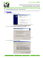
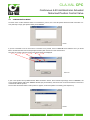
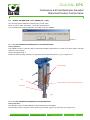
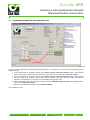
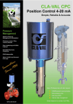
1
CLA-VAL CPC
Continuous 4-20 mA Electronic Actuated
Motorized Position Control Valve
` User Manual
` CLA-VAL Europe
www.cla-val.ch
[email protected]
© Copyright CLA-VAL Europe - Specifications subject to change without notice - no contractual illustrations.
1 - LIN040UE
B 10/09
CLA-VAL CPC
Continuous 4-20 mA Electronic Actuated
Motorized Position Control Valve
Table of Contents
1 ` Introduction..................................................................................................................... 3
1.1
1.2
1.3
1.4
1.5
Precautions Before Starting ......................................................................................................3
Troubleshooting ........................................................................................................................3
General Disclaimer ...................................................................................................................3
Environmental Protection..........................................................................................................3
Typography ...............................................................................................................................4
2 ` CPC Characteristics ....................................................................................................... 5
3 ` How to Use the CPC? ..................................................................................................... 6
3.1
3.2
3.3
3.4
3.5
3.6
3.7
3.8
3.9
Wiring Connections...................................................................................................................6
CPC Technical Data .................................................................................................................7
Connection................................................................................................................................8
Installation Instructions .............................................................................................................9
Software / Firmware Update .....................................................................................................9
Firmware Update (Internal Software)......................................................................................10
USB Driver Installation............................................................................................................10
Update USB Driver or Install on another Port .........................................................................11
Configuration Mode.................................................................................................................13
4 ` How to calibrate the CPC? ........................................................................................... 14
4.1 Display ....................................................................................................................................14
4.2 Static Calibration - Full Range (0% - 100%) ...........................................................................15
4.2.1
4.2.2
4.2.3
4.3
4.4
4.5
4.6
0%-100% Calibration Mode WITHOUT System Pressure...............................................................15
0%-100% Calibration Mode WITH System Pressure ......................................................................15
0-100% Calibration Mode WITH or WITHOUT System Pressure ...................................................16
Calibration - Variable Range...................................................................................................17
Extended Calibration: High Position Point ..............................................................................18
Configuration...........................................................................................................................19
Alarms.....................................................................................................................................20
5 ` Some Tips .....................................................................................................................21
` CLA-VAL Europe
www.cla-val.ch
[email protected]
© Copyright CLA-VAL Europe - Specifications subject to change without notice - no contractual illustrations.
2 - LIN040UE
B 10/09
CLA-VAL CPC
Continuous 4-20 mA Electronic Actuated
Motorized Position Control Valve
1
` INTRODUCTION
1.1
PRECAUTIONS BEFORE STARTING
: Before commencing work on site, connect to our internet address to update your CPC with the latest version of the
Software and Firmware (chapter 3.5).
1.2
TROUBLESHOOTING
•
Diagnostic for the LED
At start-up, the LED remains red for 5 seconds, then switches to solid Green.
•
Green
Status OK.
•
No light
Check power supply.
•
Red
Exceed the High torque limit - Power down and power up again. If problem persists contact CLA-VAL.
Excess Voltage (Above 32 V).
•
Blinking red/green
Calibration was not completed correctly - recalibrate.
•
Changing a set-point without a command signal with a CPC - USB cable connected
1. Calibrate your range.
2. Select ‘Last position’ in loss of signal mode.
3. Go to ‘Display’ tab, select your Milliamp value and tick the check box to activate.
1.3
GENERAL DISCLAIMER
In accordance with our policy of continuous development and improvement, CLA-VAL Europe reserves the right to modify or
improve these products at any time without prior notice. CLA-VAL Europe assumes no liability or responsibility for any errors
or omissions in the content of this document.
1.4
ENVIRONMENTAL PROTECTION
Help to preserve and protect the environment. Recycle used batteries and accessories.
` CLA-VAL Europe
www.cla-val.ch
[email protected]
© Copyright CLA-VAL Europe - Specifications subject to change without notice - no contractual illustrations.
3 - LIN040UE
B 10/09
CLA-VAL CPC
Continuous 4-20 mA Electronic Actuated
Motorized Position Control Valve
1.5
TYPOGRAPHY
Throughout this manual, the following typographical conventions and symbols have been adopted to help readability:
a.
"Bold": Menu, command, tab and button.
b.
BOLD ITALIC: Important information.
c.
(1): Number of the reference marks on image.
d.
www.cla-val.ch: Internet address.
e.
: Some tips.
f.
: Warning!
` CLA-VAL Europe
www.cla-val.ch
[email protected]
© Copyright CLA-VAL Europe - Specifications subject to change without notice - no contractual illustrations.
4 - LIN040UE
B 10/09
CLA-VAL CPC
Continuous 4-20 mA Electronic Actuated
Motorized Position Control Valve
2
` CPC CHARACTERISTICS
Thank you for purchasing a CLA-VAL CPC. With appropriate care, this CPC will provide accurate and reliable control of your
valve for many years. The CPC is built with the latest technology together with very high quality components.
The CPC is a 4-20 mA standalone actuated control which is PC calibrated and able to remotely control any CLA-VAL valve.
The pilot setting can be adjusted with a standard 4-20 mA signal. It also incorporates a 4-20 mA position feedback signal to
cross check if the requested position is reached.
CPC
Maintenance port
Led indicator
Power supply cable
moulded 10 meter
standard execution
Security High Sensor
Input/Output cable moulded
10 meter standard execution
Security Low Sensor
Maintenance cable
Adaptable side
PC Connection
Adapter socket
CPC Connection
` CLA-VAL Europe
www.cla-val.ch
[email protected]
© Copyright CLA-VAL Europe - Specifications subject to change without notice - no contractual illustrations.
5 - LIN040UE
B 10/09
CLA-VAL CPC
Continuous 4-20 mA Electronic Actuated
Motorized Position Control Valve
3
` HOW TO USE THE CPC?
3.1
WIRING CONNECTIONS
Cable 1
Code cable 1
Cable 1 function
Colour
Connect with ground
principal
0V
+24 VDC
Power supply
blue
brown
Cable 2
Code cable 2
` CLA-VAL Europe
Cable 2 function
Colour
+4-20 mA
Position Feedback
green
Common -
For position feedback &
contact security
+4-20 mA-
Set point +
yellow
-4-20 mA
Set point -
grey
Alarm 1
Input low contact relay
Alarm 1
Output low contact relay
blue
Alarm 2
Input high contact relay
orange
Alarm 2
Output high contact relay
pink
brown
white
Low security
Low contact security
turquoise
High security
High contact security
purple
www.cla-val.ch
[email protected]
© Copyright CLA-VAL Europe - Specifications subject to change without notice - no contractual illustrations.
6 - LIN040UE
B 10/09
CLA-VAL CPC
Continuous 4-20 mA Electronic Actuated
Motorized Position Control Valve
3.2
CPC TECHNICAL DATA
Electrical Specifications
Electrical Power:
• 24 VDC, 6 / 10 / 15 rpm / sizes
300 mA max. load draw
85 mA stand-by (no load draw)
Power Protection
Max. 32 VDC over voltage
Max. 1000 mA torque load
Reverse polarity & short circuit
80°C stop @ high temperature
Led display:
Green LED
Electrical connection:
2 x Moulded 10 m cables
Input command:
• 4-20 mA (2 wires)
• 2 x dry contact (contact security)
Input 4-20 mA Protection
Max. 32 VDC over voltage
Optocoupler isolation @ CMR 1000 V
(CMR: common mode rejection)
Insulated (2 wires)
Output feedback:
• 4-20 mA (Output charge ≤ 500 Ω)
• 2 x programmable position alarms
Output 4-20 mA Protection
Max. 32 VDC over voltage
(The input dry contact and 4-20 mA output have the same common or earth
but are not individually isolated)
Other Specifications
Sizes:
GE 50 - 300 / NGE 80 - 400
Operating pressure:
PN 16 bar standard
Operation type:
Continuous Control
Operating temperature range:
-10°C to +80°C
Protection:
IP68 standard allowing full immersion (solenoid, junction box, sensor, not
included in IP68)
Interface:
Plug & Play / NT / 2000 / XP / Vista
Default mode
Troubleshooting:
Refer to user manual for LED diagnostics (red-green-blinking)
Remote command failure:
Options available: maintain current position, go to 4 mA position, go to
20 mA position
` CLA-VAL Europe
www.cla-val.ch
[email protected]
© Copyright CLA-VAL Europe - Specifications subject to change without notice - no contractual illustrations.
7 - LIN040UE
B 10/09
CLA-VAL CPC
Continuous 4-20 mA Electronic Actuated
Motorized Position Control Valve
3.3
CONNECTION
Output:
LIN040UE-09
` CLA-VAL Europe
www.cla-val.ch
[email protected]
© Copyright CLA-VAL Europe - Specifications subject to change without notice - no contractual illustrations.
8 - LIN040UE
B 10/09
CLA-VAL CPC
Continuous 4-20 mA Electronic Actuated
Motorized Position Control Valve
3.4
INSTALLATION INSTRUCTIONS
1- The CPC should be mounted in the vertical position. For a position horizontal, please contact CLA-VAL.
2- All installation, adjustment and maintenance should be carried out by a competent electrician.
3- Do not exceed the maximum ratings given in the specifications and printed on the label.
4- The electrical connections should be made as described in the user’s manual.
5- Before any maintenance operation the main power should be turned off.
: Do not attempt to open the product as this will invalidate the warranty!
3.5
SOFTWARE / FIRMWARE UPDATE
For Software updates please visit our web site www.cla-val.ch:
Select "download e-Line", you will find all the latest Software (PC) & Firmware (internal software) updates. Just click on the
logo to download automatically.
All the software is multi-language, only the install Software is in French or English.
` CLA-VAL Europe
www.cla-val.ch
[email protected]
© Copyright CLA-VAL Europe - Specifications subject to change without notice - no contractual illustrations.
9 - LIN040UE
B 10/09
CLA-VAL CPC
Continuous 4-20 mA Electronic Actuated
Motorized Position Control Valve
3.6
FIRMWARE UPDATE (INTERNAL SOFTWARE)
: Before the Firmware update, save program on your PC.
1- Connect the USB wire to the USB connection of your PC.
2- Connect the CPC to the USB wire.
3- Select "Read Parameters" to read CPC settings and record output parameters.
4- Select "Firmware update" in "Parameters".
5- Open the corresponding ".hex" file.
6- Select "Read Parameters" to check that the Firmware is updated.
3.7
USB DRIVER INSTALLATION
When you connect the CPC cable for the first time, your PC will detect it and request a driver.
Windows 1
a.
Select "Cancel".
b.
Install the "Multi-USB driver setup" software on your PC (you can download this software from the internet
www.cla-val.ch).
c.
When you see this message below, select "Continue Anyway".
Windows 3
Installation of the USB driver is now finished.
Windows 5
` CLA-VAL Europe
www.cla-val.ch
[email protected]
© Copyright CLA-VAL Europe - Specifications subject to change without notice - no contractual illustrations.
10 - LIN040UE
B 10/09
CLA-VAL CPC
Continuous 4-20 mA Electronic Actuated
Motorized Position Control Valve
3.8
UPDATE USB DRIVER OR INSTALL ON ANOTHER PORT
To update your USB driver, please follow procedure below. Install the software «Multi-USB Driver Setup» download from our
web site www.cla-val.ch.
Connect your USB cable to your PC.
a.
Select: "Install from a list or specific location".
Windows-1
b.
Browse to file: C\Program Files\CLA-VAL\Multi-USB Driver Setup.
Windows-2
c.
Microsoft validation press “Continue Anyway”
Windows-3
` CLA-VAL Europe
www.cla-val.ch
[email protected]
© Copyright CLA-VAL Europe - Specifications subject to change without notice - no contractual illustrations.
11 - LIN040UE
B 10/09
CLA-VAL CPC
Continuous 4-20 mA Electronic Actuated
Motorized Position Control Valve
d.
Installation.
Windows-4
e.
Installation completed.
Windows-5
Visit our web site www.cla-val.ch frequently to download the latest updates and news.
` CLA-VAL Europe
www.cla-val.ch
[email protected]
© Copyright CLA-VAL Europe - Specifications subject to change without notice - no contractual illustrations.
12 - LIN040UE
B 10/09
CLA-VAL CPC
Continuous 4-20 mA Electronic Actuated
Motorized Position Control Valve
3.9
CONFIGURATION MODE
To launch CPC / e-Drive Software when not connected to your PC, the e-Line list (which allows the multi connection of eLine products) is empty (see picture below), click "Cancel".
GEN001
If you are connected to one or more CPC’s or another e-Line product, click on "View All" then select the CPC you would
like to communicate with from the list (see picture below) then click once on left mouse button.
The name of product, Firmware version and serial number are displayed.
LIN040U-01
If your e-Line product isn’t updated with the “Multi connection” version, the e-Line list stays empty. Click on "View All", the
e-Line product appears with name "Generic e-Line" (see picture below), then click once on left mouse button on this line to
communicate with the product.
For the name and serial number of this product to appear, a Firmware update is necessary (see chapter 3.6).
GEN002
` CLA-VAL Europe
www.cla-val.ch
[email protected]
© Copyright CLA-VAL Europe - Specifications subject to change without notice - no contractual illustrations.
13 - LIN040UE
B 10/09
CLA-VAL CPC
Continuous 4-20 mA Electronic Actuated
Motorized Position Control Valve
` HOW TO CALIBRATE THE CPC?
DISPLAY
Activated continuous
reading
Activated override
set point
Configuration information
4.1
General
information
4
Display pressure values
Display Set point and
feedback position
LIN040UE-01
Connect your PC to the CPC with the USB cable.
1-
Start the CPC / e-Drive CLA-VAL Software.
2-
Selected the CPC in the e-Line list.
3-
Selected your language and click "Read parameters".
4-
On the right side the configuration information is displayed. On the top general information including the date of
the latest calibration, the average & total working time since the first power up, the number of starts, the serial
number, the Firmware version and the maximum and minimum recorded temperature is displayed.
5-
Click on continuous reading if you would like see the position of CPC, set point (mA) and feedback position (mA
and units).
6-
If you would like to manually change the setting, write your setting and click on "Override Setpoint".
Improper use of "Override Setpoint" may cause damage to your system.
: a- Display configuration text colour is blue by default. If you amend any parameters, the text colour will change to
black. To restore text to blue, select "Read parameters".
` CLA-VAL Europe
www.cla-val.ch
[email protected]
© Copyright CLA-VAL Europe - Specifications subject to change without notice - no contractual illustrations.
14 - LIN040UE
B 10/09
CLA-VAL CPC
Continuous 4-20 mA Electronic Actuated
Motorized Position Control Valve
4.2
STATIC CALIBRATION - FULL RANGE (0% - 100%)
The “Set range” allows calibration in either dynamic or static mode.
When you click on folder “Set Range”, you see this message below.
If you would like to proceed with calibration, click "OK", if not click "Cancel".
LIN039UE-02
4.2.1 0%-100% CALIBRATION MODE WITHOUT SYSTEM PRESSURE
Initial preparation:
This calibration mode is commonly used for either field installations where there is no water in the valve (Valve is naturally
closed) or Factory settings.
Remove the plug (see Fig. 1).
Position the orifice coupling until there is no gap (flush) with the stem tube (see Fig. 1), go to chapter 4.2.3.
Orifice coupling
Plug
No gap between orifice coupling and stem tube
Stem tube
Fig. 1
4.2.2 0%-100% CALIBRATION MODE WITH SYSTEM PRESSURE
Initial preparation:
This calibration mode is for field installations where water pressure is available.
Use necessary means to verify the valve is closed e.g. Flow meter, gauge or by sound then go to chapter 4.2.3.
` CLA-VAL Europe
www.cla-val.ch
[email protected]
© Copyright CLA-VAL Europe - Specifications subject to change without notice - no contractual illustrations.
15 - LIN040UE
B 10/09
CLA-VAL CPC
Continuous 4-20 mA Electronic Actuated
Motorized Position Control Valve
4.2.3 0-100% CALIBRATION MODE WITH OR WITHOUT SYSTEM PRESSURE
Select the valve size to be calibrated from the drop down menu (3).
To determine the number of turns required to achieve the complete lift.
Open CPC / e-Drive Software then go to "Set Range" tab and click OK on the menu.
1- Select "Static Calibration" Mode and check "CPC Motor" box is checked and select trim size from the drop down
menu (3).
2- Select units.
3- Enter 4 mA value and 20 mA value.
Using the "Increase actuator"/ "Decrease actuator" Buttons, adjust the position of the orifice coupling until there
is no gap (flush) with the stem tube (See Fig. 1, page 15).
4- Turns to low point (1): Enter the number ‘1’.
5- Turns to high point (2): Enter the “Number of turns” value for the valve selected (4).
7- Select "Write Set Range" to upload settings to CPC.
Your CPC is calibrated.
Go to chapter 4.5.
(3)
(1)
(4)
(2)
LIN040UE-05
` CLA-VAL Europe
www.cla-val.ch
[email protected]
© Copyright CLA-VAL Europe - Specifications subject to change without notice - no contractual illustrations.
16 - LIN040UE
B 10/09
CLA-VAL CPC
Continuous 4-20 mA Electronic Actuated
Motorized Position Control Valve
4.3
CALIBRATION - VARIABLE RANGE
Calibration Mode to a specific process WITH System pressure.
Initial preparation:
This calibration mode is for field installations where water pressure is available and you want to control flow over a specific
range of positions.
Now you are in the calibration, please enter the required settings:
LIN040UE-03
1- Select "Dynamic Calibration" mode and ensure that the "CPC Motor" check box is checked (Enabled).
2- Select units.
3- Enter the required setting Value at 4 mA point and Value at 20 mA point.
4- Look at the position on the display and use the "Increase actuator / Decrease actuator" button, until it reaches
the low position point. When the low position point is reached then click on the button "Low point setting".
5- Look at the position on the display and use the "Increase actuator / Decrease actuator" button, until it reaches
the high position point. When the high position point is reached then click on the button "High point setting".
7- When all values have been entered, click on "Write Set Range".
Your calibration is done.
` CLA-VAL Europe
www.cla-val.ch
[email protected]
© Copyright CLA-VAL Europe - Specifications subject to change without notice - no contractual illustrations.
17 - LIN040UE
B 10/09
CLA-VAL CPC
Continuous 4-20 mA Electronic Actuated
Motorized Position Control Valve
4.4
EXTENDED CALIBRATION: HIGH POSITION POINT
Projected calibration
LIN040UE-04
If you can not physically reach the requested High position point, in this situation you have to follow the extended dynamic
calibration mode:
4- Look at the position on the display and use the "Increase actuator / Decrease actuator" button, until it reaches
the low position point. When the low position point is reached then click on the button "Low point setting".
5- Look at the position on the display and use the "Increase actuator / Decrease actuator" button, until it reaches
the high position point. When the position does not increase any more then stop the actuator. Decrease the
position by a small amount, as soon as you see the display changing stop again.
6- Enter the indicated value in the projected calibration window "Attainable high point value" as described above,
then click on "High point setting".
7- When all values have been entered, click on "Write Set Range".
Your calibration is done.
` CLA-VAL Europe
www.cla-val.ch
[email protected]
© Copyright CLA-VAL Europe - Specifications subject to change without notice - no contractual illustrations.
18 - LIN040UE
B 10/09
CLA-VAL CPC
Continuous 4-20 mA Electronic Actuated
Motorized Position Control Valve
4.5
CONFIGURATION
The configuration tab sets the Rotation speed and the Deadband.
•
The Rotation speed affects the response time of the valve between set-points.
The default condition is 0 seconds "On-time" and 0 seconds "Off-time" achieving continuous rotation speed which
will vary corresponding to the size of your valve.
Make sure that the values entered are appropriate to your system to minimise potential for surge.
•
Dead band - The default value is 0.1 mA which may need to be increased depending on the stability of the
electrical signal.
Choose the loss of signal mode.
•
Go to 4 mA:
CPC will default to the 4 mA position (low set point).
•
Last position:
CPC will maintain the last position.
•
Go to 20 mA:
CPC will default to the 20 mA position (high set point).
Note: Loss of signal can occur on the SCADA system which generates the 4-20 mA command but at the same time the
CPC can stay powered, so it is important to select the right option.
When you have finished your configuration, click on "Write Configuration".
Your CPC is configured.
LIN040UE-06
` CLA-VAL Europe
www.cla-val.ch
[email protected]
© Copyright CLA-VAL Europe - Specifications subject to change without notice - no contractual illustrations.
19 - LIN040UE
B 10/09
CLA-VAL CPC
Continuous 4-20 mA Electronic Actuated
Motorized Position Control Valve
4.6
ALARMS
The CPC incorporates a LOW and HIGH Alarm with an adjustable hysteresis.
Note: The low and High alarm levels are activated within the range:
•
Example:
10% low alarm = 4 + (10% x 16) = 5.6 mA.
90% High alarm = 4 + (90% x 16) = 18.4 mA.
•
Hysteresis:
The calculation is: 4 + (2% x 16) = 0.32 mA.
Low alarm hysteresis in this example = 5.6 mA + 0.32 mA = 5.92 mA.
High alarm hysteresis in this example = 18.4 mA - 0.32 mA = 18.08 mA.
Enter the requested percentage, for the alarms and hysteresis.
2-
Click on "Test" to close or open your contact relay.
3-
Click on "Write Alarms" (1) once your alarm settings are correct.
Adjustment of alarms high, low
level and hysteresis alarm level
2%
1-
(1)
LIN040UE-07
"Low Level" alarm
range
"Low Level" alarm
value
"Low Level" hysteresis alarm
value
` CLA-VAL Europe
www.cla-val.ch
"High Level" alarm
range
"High Level" alarm
value
"High Level" hysteresis
alarm range
[email protected]
© Copyright CLA-VAL Europe - Specifications subject to change without notice - no contractual illustrations.
20 - LIN040UE
B 10/09
CLA-VAL CPC
Continuous 4-20 mA Electronic Actuated
Motorized Position Control Valve
` SOME TIPS
5
a.
To generate a calibration report, select "Parameters" and then "Report".
•
Enter a reference number.
•
Click on "Report".
The Software will automatically generate a TXT report file (C:\Program Files\CLA-VAL\e-Drive Setup) including all
the calibration settings.
b.
To retrofit CPC motor to an existing valve refer to the <<Retrofit Instructions>>.
` CLA-VAL Europe
www.cla-val.ch
[email protected]
© Copyright CLA-VAL Europe - Specifications subject to change without notice - no contractual illustrations.
21 - LIN040UE
B 10/09