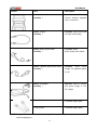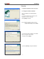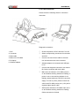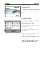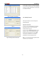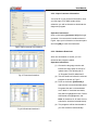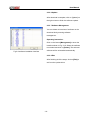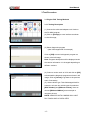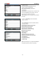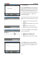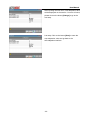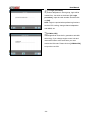
1
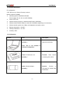
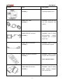
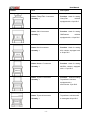
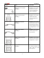
PC-MAX
Wireless Automotive Diagnostic System
USER MANUAL
Version 1.0
User Manual
Statement
Copyright © 2009 by AUTOBOSS TECH. INC. (short for "AUTOBOSS"). All rights reserved. No part of
this publication can be reproduced, stored in a retrieval system, or transmitted in any form or by any
means, electronic, mechanical, photocopying, recording or otherwise, without the prior written
permission of AUTOBOSS. The information contained herein is designed only for the use of this unit.
AUTOBOSS is not responsible for any use of this information as applied to other units.
Neither AUTOBOSS nor its affiliates shall be liable to the purchaser of this unit or third parties for
damages, losses, costs, or expenses incurred by purchaser or third parties as a result of: accident,
misuse, or abuse of this unit, or unauthorized modifications, repairs, or alterations to this unit, or
failure to strictly comply with AUTOBOSS operating and maintenance instructions.
AUTOBOSS shall not be liable for any damages or problems arising from the use of any options or
any consumable products other than those designated as Original AUTOBOSS Products or
AUTOBOSS Approved Products by AUTOBOSS.
General Notice: Other product names used herein are for identification purposes only and may be
trademarks of their respective owners. AUTOBOSS disclaims any and all rights in those marks.
The PC-MAX can only be operated by qualified technicians.
Trade mark
AUTOBOSS is a registered trademark of AUTOBOSS TECH. INC. (short for AUTOBOSS) in China
and other countries. All other AUTOBOSS trademarks, service marks, domain names, logos, and
company names referred to in this manual are either trademarks, registered trademarks, service
marks, domain names, logos, company names of or are otherwise the property of AUTOBOSS or its
affiliates. In countries where any of the AUTOBOSS trademarks, service marks, domain names, logos
and company names is not registered, AUTOBOSS claims other rights associated with unregistered
trademarks, service marks, domain names, logos, and company names. Other products or company
names referred in this manual may be trademarks of their respective owners. You may not use any
trademark, service mark, domain name, logo, or company name of AUTOBOSS or any third party
without permission from the owner of the applicable trademark, service mark, domain name, logo, or
company name.
You may contact AUTOBOSS by visiting AUTOBOSS at www.obdchina.com , or writing to
AUTOBOSS, Feicui Huating, Bao’an District,518010 Shenzhen, China , to request written permission
to use Materials on this manual for purposes or for all other questions relating to this manual.
-I-
User Manual
PC-MAX User Manual instructions
l
Please read this user manual carefully before using the scanner.
l
The current user manual is based on the current features and functions available. Any new
added features and functions of PC-MAX will be added to the user manual in the future. Updated
versions of user manual will be available to download at AUTOBOSS website
(http://www.obdchina.com).
l
When reading the manual, please pay special attention to the words “Note”, “Caution” and
“Warn”. Read them carefully for appropriate operation.
PC-MAX main unit maintenance:
l
Avoid shaking or dismantling as it may damage the internal components
l
Do not use hard or sharp objects to touch it; do not use excessive force; do not expose the
screen to strong sunlight for a long period
l
Caution: keep it away from water, moisture, high temperature or very low temperature;
l
Keep the main unit away from strong magnetic fields.
Operation Instructions
l
For safe operation please follow the instructions below;
l
Keep the scanner away from heat or fumes when using it;
l
If the vehicle battery contains acid, Please keep your hands and skin or fire sources away from
the battery during test
l
Exhaust gas of vehicle contains harmful chemicals, please ensure adequate ventilation.
l
Do not touch the cooling system components or exhaust manifolds when engine is running to
high temperature;
l
Make sure the car is securely parked and the selector is at P or N position to prevent the vehicle
from moving when engine starts;
l
Make sure the diagnostic link connector (DLC) is OK before starting the test; otherwise the
scanner may be damaged. Autoboss suggests you test the Power/Earth with multi-meter first.
l
Do not switch off the power or unplug the connectors during testing, otherwise you may damage
the ECU or scanner;
- II -
User Manual
Content
1 Introduction .................................................................................................................................1
1.1 FUNCTION AND FEATURE ...........................................................................................................1
1.2 LAYOUT OF MAIN UNIT ..............................................................................................................1
1.3 TECHNICAL PARAMETERS ..........................................................................................................2
1.4 CONFIGURATION ......................................................................................................................2
2 Operation ....................................................................................................................................7
2.1 SOFTWARE INSTALLATION & CABLE CONNECTION ...........................................................................7
2.1.1 Diagnostic software installation ......................................................................................7
2.1.2 Cable connection ..........................................................................................................8
2.2 INTERFACE INSTRUCTION ..........................................................................................................9
2.2.1 Starting Interface ...........................................................................................................9
2.2.2 Diagnostic Program.......................................................................................................9
2.2.3 System Setting............................................................................................................10
2.2.4 Self check ................................................................................................................... 11
2.2.5 Version Information ..................................................................................................... 11
2.2.6 Homepage .................................................................................................................. 11
2.2.7 Print............................................................................................................................ 11
2.2.8 Exit .............................................................................................................................12
2.3 SOFTWARE UPDATE ................................................................................................................13
2.3.1 Upgrading Instructions.................................................................................................13
3 Test Procedure ..........................................................................................................................17
3.1 Engine ECU Testing Methods .........................................................................................17
Order Information .........................................................................................................................25
- III -
User Manual
1 Introduction
1.1 Function and Feature
l
OE level coverage for European, Asian,
American and Chinese cars
l
Supports Multi-language
l
Multi-functions
l
Wireless diagnosis operated on PC
l
CAN-BUS with high/low speed
l
One OBDII connector for all CAN bus
systems
l
Continuous software update online
l
6-layer electronic circuit board
l
Self-check function
1.2 Layout of Main Unit
The main unit layout is as shown in left picture.
① PC/laptop (NOT INCLUDED)
② Wireless adaptor
③ PC-MAX main unit
④ Vehicle (ECU)
⑤ Main cable port
⑥ Power indicator
⑦ Wireless operation indicator
⑧ USB port
⑨ Power supply (+12V) port
-1-
User Manual
1.3 Technical Parameters
PC configuration
CPU: Pentium 4 (or Celeron R series) or above
Memory: Minimum 256MB
l
Operating system: WINDOWS XP/2000
Power supply: DC 12V, AC 110~250V 50/60Hz;
l
Power: DC 9~15V
l
Wireless working frequency: 2400 MHz-2483.5 MHz. (ISM-Band)
l
Wireless communication distance: around 20~100 Meters (depending on environment)
l
Wireless transfer speed: max. 2Mbps, self-adaptation and power control
l
Memory temperature: -30~90ºC
l
Working temperature: -10~70ºC
l
Humidity: <90%
1.4 Configuration
Picture
Item
Description
Name: PC/laptop
Function: Used for wireless
Quantity: 1
diagnosis and display
Note: This is not included in
standard configuration.
Name: PC-MAX main unit
Function:
Quantity: 1
connecting with vehicle
Name: Wireless adaptor
Function:
Quantity:1
PC/Laptop for wireless data
transmission
-2-
Data
transfer
Connect
to
User Manual
Picture
Item
Description
Name: Installation CD
Function: Used to install
Quantity: 1
operating software in PC
Name: Main Cable
Function: Connect the main
Quantity: 1
unit and connectors with
vehicle
Name: BENZ-38 connector
Function: Used for testing
Quantity: 1
Mercedes-Benz
vehicles
equipped with a circular
38-pin DLC
Name: Benz-14 connector
Function: Used for testing
Quantity: 1
Mercedes-Benz sprinter
Name: Chrysler-16 connector
Function: Used for testing
Quantity: 1
Chrysler with CCD protocol
Note: Optional adaptor
Name: BMW-20 connector
Function: Used for testing
Quantity: 1
BMW
vehicles
with a 20-pin DLC
-3-
equipped
User Manual
Picture
Item
Description
Name: Chery/Fiat -3 connector
Function: Used for testing
Quantity: 1
Chery/Fiat
vehicles
equipped with a 3-pin DLC
Name: GM-12 connector
Function: Used for testing
Quantity: 1
GM/Daewoo
vehicles
equipped with a 12-pin DLC
Name: Kia-20 connector
Function: Used for testing
Quantity: 1
KIA vehicles equipped with
a 20-pin DLC
Name: Mazda-17 connector
Function: Used for testing
Quantity: 1
MAZDA vehicles equipped
with a 17-pin DLC
Name: Toyota-17 connector
Function: Used for testing
Quantity: 1
Toyota/Lexus vehicles
equipped with a
semi-circular 17pin DLC
Function: Used for testing
Name: Toyota-22 connector
Toyota/Lexus vehicles with
Quantity: 1
a rectangular 22-pin DLC
-4-
User Manual
Picture
Item
Description
Name: MIT-12+16 connector
Function: Used for testing
Quantity: 1
Mitsubishi and Hyundai
vehicles equipped with a
12-pin or 16-pin DLC
Name: Honda-3 connector
Function: Used for testing
Quantity: 1
HONDA and ACURA
vehicles equipped with a
3-pin DLC
Name: Benz-4 connector
Function: Used for testing
Quantity: 1
Mercedes-Benz before 1997
with flash codes, which are
usually equipped with either
a rectangular 8-pin or 16-pin
DLC
Name: Audi-4 connector
Function: Used for testing
Quantity: 1
VW/Audi vehicles with a
4-pin (2x2) DLC
Name: Nissan-14 connector
Function: Used for testing
Quantity: 1
Nissan and Infiniti vehicles
equipped with a 14-pin DLC
Name: OBD-16 connector
Function: Used for testing
Quantity: 1
all vehicles compliant with
OBDII, EOBD and J1962
with 16-pin DLC
-5-
User Manual
Picture
Item
Description
Name: Citroen-16C connector
Function: Used for testing
Quantity: 1
Citroen vehicles equipped
with a 16-pin DLC
Name: Jumper
Function: Short circuit test
Quantity: 1
for flash code reading
Name: Battery power cable
Function: Gains
Quantity: 1
power supply from battery
Name: Cigarette lighter power cable
Function:
Quantity: 1
supply via cigarette lighter
Gains
power
on car
Name: DC adaptor
Function: Used to connect
Quantity: 1
with power supply of 12V
DC voltage
Fuse 5A 30*6
Function: Spare parts
Fuse 5A 20*5
Function: Spare parts
NOTE: Configuration varies as per software package. For complete configuration, please refer to the
relevant shipping list.
-6-
User Manual
2 Operation
2.1 Software installation & cable connection
2.1.1 Diagnostic software installation
Steps for installation of PC-MAX diagnostic
software:
(1). Put the PC-MAX CD into CD driver in PC.
Installation information will popup.
Click on [Next] to continue.
(2). In PC-MAX installation interface, click on
[I agree this license] and then [Next].
(3). Choose the path for installation. The default
path is C:\Program Files\PC-MAX.
To continue, click on [Next].
(4). Click on [Finish] to complete Installation.
.
-7-
User Manual
2.1.2 Cable connection
Please check the following chart for connection
instruction:
Diagnostic connection:
1. DLC
① Check the position of DLC and see if it is OK.
2. Connector
② Select corresponding connectors for car make
3. Main cable
4. Main unit of PC-MAX
and DLC.
③ Connect one end of main cable to the main
5. PC/laptop
6. Wireless adaptor
unit and the other end to the connector.
④ Wireless adaptor is connected with USB port
in PC
⑤ Connect the diagnostic connector with vehicle
DLC after connecting with main cable.
⑥ Make sure the indicator of PC-MAX power is
on and wireless working indicator is flashing. If
power is not on and working indicator is not
flashing, please make sure the DLC has power
supply. If it has no power, please connect the
vehicle with PC-MAX power port (+12V) with a
cigarette lighter power cable.
⑦ When power indicator of PC-MAX main unit is
on and wireless working indicator is flashing.
Cable connection is finished.
-8-
User Manual
2.2 Interface Instruction
2.2.1 Starting Interface
The interface shown on the left picture will appear
on the screen after the PC-MAX software is run on
PC.
2.2.2 Diagnostic Program
In the diagnostic interface you can select regional
vehicle makes including: China, Europe, Asia,
America and Others (OBDⅡ/EOBD).
Europe: This section includes diagnostic programs
for European vehicles.
Asia: This section includes diagnostic programs for
Asian vehicles.
America:
This
section
includes
diagnostic
programs for American vehicles.
China: This section includes diagnostic programs
for Chinese vehicles.
Others: This diagnostic program can test all
vehicles with OBDⅡ/EOBD and CAN-OBD.
-9-
User Manual
2.2.3 System Setting
Click on the button [Option] to enter settings
for language, Compulsive download MCU
software and communication port selection.
.2.2.3.1 Language Setting
PC-MAX supports Multilanguage. Choose any
language needed under [working language] and
press [OK] to finish language setting.
2.2.3.2 Compulsive download MCU software
If you choose this option, it will download the
program again every time when you choose a car
for testing in order to insure the success of test.
2.2.3.3 Select communication port
After connecting with wireless adaptor, you will see
different options for communication port selection.
If there is more that one port, please choose the
right one.
- 10 -
User Manual
2.2.4 Self check
This is for hardware checking. Click on the button
[Self check] in [Option] and any hardware faults
will be displayed. Please contact local distributor if
a hardware problem is reported.
If there are no hardware errors, the checking result
will be like the left photo.
Note: The main cable should be disconnected
when self checking. And PC-MAX main unit is
connected with power supply.
2.2.5 Version Information
Click on the button [About] in [Option] to get the
version information of Hardware, Software Serial
number, Release date, etc
You will also see the register password at the
bottom.
Note: Every time when you enter
“PC-MAXClient.exe”, you will need the serial
number and password to login.
2.2.6 Homepage
Due to certain reasons, the operating interface may
freeze up. You could click on the button [Home] to
exit and continue testing.
2.2.7 Print
Every time when you click on [Print], the
information will be saved in the folder named ”print”
in your PC. To print the information, please refer to
the relevant path.
- 11 -
User Manual
2.2.8 Exit
Click on [Exit] of main menu and choose [OK] to
exit from the operating program and choose
[Cancel] to continue the diagnosis.
- 12 -
User Manual
2.3 Software update
2.3.1 Upgrading Instructions
2.3.1.1 Run PC-MAX update client program
Double click to run the “PC-MAXClient.exe”
program under the folder named “tools” in the
CD program. You will go to update interface as
shown in Fig 2-1.
2.3.1.2 Login the Server
(1) Input the serial number and click on
[Connect to server] to enter the Fig 2-2
Fig 2-1 update client starting interface
interface.
(2) Server. The default server is
‘www.obdchina.com’. Normally you do not
need to change the server.
(3) Input the password (see 2.2.5) and click on
[OK].
Note:
① Be sure that both S/N and password are
Fig 2-2 login interface
correct. Please pay attention if the
letters are capitalized or not.
② If login takes a long time because of low
internet speed, you can exit and retry;
③ Internet firewall might affect the login. If
login fails, please make sure you have
an internet connection, and ensure any
installed firewall is not blocking the
connection to the server. You may
contact your local distributor for further
operating instructions.
- 13 -
User Manual
(4) After login succeeds, the diagnosis program
for the different manufacturers will be displayed
as shown in Fig2-3, please wait for a short time
for complete download.
Fig2-3 Program list interface
2.3.3.3 Modify Password
After login succeeds, users can change the
original password.
Operation instruction:
Fig2-4
(1) Click on the button [Connect to server] in
the interface shown in Fig.2-3 to enter the
interface shown in Fig.2-4.
(2) Click on button [Modify password] to enter
interface in Fig.2-5. After inputting the current
password and new password, click on [OK].
You will get a confirmation for successful
modification if the new password is OK.
Fig2-5 Modify password interface
Note: If you forget the password, please contact
Autoboss or your local dealer.
- 14 -
User Manual
2.3.3.4 Input Customer Information
You must fill in your personal information when
you first login to PC-MAX update client;
otherwise you will not be able to download the
diagnostic program.
Operation instruction:
Click on the button [Customer info] after login
succeeds. You can see the interface shown in
Fig2-6. Input your information in relevant space
and click [OK] to save the information.
Fig2-6 Input customer info interface
2.3.3.5 Software Download
After user information is saved, you can
download the program needed.
Operation instruction:
(1) Choose the language version and
browse the setup path on the top of
update client. The default path is
“C:\Program Files\PC-MAX\work\”.
Fig.2-7 Download interface
(2) Tick the small box before the relevant
program as shown in Fig.2-7;
(3) Click on the button [Download] in
right column to enter download status.
Programs that are not downloaded
are in black. If download succeeds,
they will be highlighted in blue. Failed
downloads are highlighted in red.
Note: A maximum of 10 items can be
selected to download simultaneously.
(4) The programs will be downloaded to
your PC hard drive automatically.
Fig.2-8 Download interface 2
- 15 -
User Manual
2.3.3.6 Update
After download is complete, click on [Update] on
the right column to finish the software update.
2.3.3.7 Software Management
You can delete old versions of software on the
download list by entering software
management.
Operating instruction:
Click on the button [Management] to enter the
interface shown in Fig. 2-10. Select the software
not needed and click on [Delete]. The selected
Fig.2-9 software installation interface
software will be uninstalled automatically.
2.3.3.8 Exit
After finishing all of the steps, click on [Exit] to
exit from the update client.
- 16 -
User Manual
3 Test Procedure
3.1 Engine ECU Testing Methods
3.1.1 Testing Description
(1) Connect the cable and adaptors well. And run
the PC-MAX program.
(2) Click on [Europe] to enter interface as shown
on the left image;
(3) Select diagnostic program
(take Volkswagen/Audi for example)
Click on [VW] to enter its diagnostic program as
shown in the left image.
Note: Program descriptions will be displayed under
the version information. It is changed depending on
different versions.
(4). Select a version such as V3.2 and click on [OK]
to download the diagnosis program as shown in left
image. Click on [Cancel] to go back to the previous
menu if necessary;
(5). Select vehicle type. Take Volkswagen/Audi for
example, we have two vehicle types for selection:
[With Canbus] and [Without Canbus]. Here we
choose [Without CANbus] as an example to
introduce the test.
NOTE: VEHICLES WITH CANBUS WILL HAVE
DLC PINS 6 AND 14 POPULATED
- 17 -
User Manual
(6) Select system:
[Common system Auto-Scan]: Test the
common-use ECU automatically;
[All system Auto-Scan]: Test all ECU
automatically;
[Common]: by choosing this item, all common-use
ECU will be displayed on the screen, users can
then select ECU required accordingly;
Other systems: Enter the systems as per relevant
ECU type.
(7) Click on [Common] to enter the interface
shown on the left.
Select [01-Engine] to enter the interface with the
following functions.
[01-Interrogate control unit versions]
[02-Interrogate fault memory]
[03-Final control diagnosis]
[04-Introduction of basis setting]
[05-Erase fault memory]
[06-End output]
[07-Coding]
[08-Read measuring value block]
[09-Read individual measuring value]
[10-Adaptation]
[11-Login procedure]
[15-Write VIN]
Note: Functions 04,07,10,15 require knowledge of
the systems operation, please use properly.
- 18 -
User Manual
①[01-Interrogate control unit versions]
Click on [01-Interrogate control unit versions] to
see the information of control unit as shown on the
left.
Note: Read out old ECU codes with this function
when performing ECU coding.
② [02-Interrogate fault memory]
To display the DTC saved in the current control unit,
click [02-Interrogate fault memory]. Please refer
to the left image.
③ [03-Final control diagnosis]
Click on the button [03-Final control diagnosis] to
test relevant actuator automatically as shown on
the left image. Click on [Active Test] to begin the
actuator test.
④ [04-Introduction of basis setting]
Click on the button [04-Introduction of basis
setting] for basic setting. Input desired text using
the number keys and click on the button [OK] to
start the basic setting.
l
[Del]: Delete the input numbers;
l
[Left]: Move cursor to left;
l
[Right]: Move cursor to right;
l
[Home]: Move cursor to Home;
l
[End: Move cursor to End;
l
[Enter]: confirm enters.
- 19 -
User Manual
The window of “Basic setting!” in left image will
popup after Basic Setting is done.
l
[Input]: continue to Input Channel number;
l
[Back]: Back to the Function Menu.
Note: Under basic setting mode, you can perform
solenoid and engine control unit adaptation without
starting the engine, or finish λ control process
self-adaptation when engine starts. Also you can
check faults or ignition timing by connecting or
disconnecting λ control.
⑤ [05-Erase fault memory]
Click on the button [05-Erase fault memory] to
erase DTC as shown on the left image.
l
[OK]: Return to the previous menu
⑥ [06-End output]
To exit from the diagnostic program, please click on
[06-End output].
l
[Yes]: Exit the diagnosis program
[No]: Return to the previous menu
⑦ [07-Coding]
Click on [07-Code control unit] to go to interface
shown in left image. Then input the code and click
on [OK], the scanner will begin the coding. Click on
[OK] after coding succeeds.
Note: Please only code the ECU after the ECU has
been changed or a function has been added (ie
Cruise control). You can get the code of the old
ECU by choosing [01-Interrogate control unit
versions], then recode the new ECU accordingly.
- 20 -
User Manual
⑧ [08-Read measuring value block]
Click on [08-Read measuring value block] to
enter interface shown in left image. Please input
the relevant channel number, and click on [OK] to
read data stream information.
Note: For channel definition, please refer to
relevant technical manual.
The left image is the data stream of Group 01.
l
[PageUp]: See previous group data stream;
l
[PageDown]: See next group data stream;
l
[Waveform]: Review data stream in graph;
l
[Replay]: Review data stream;
l
[Channel]: Return to the interface to input
channel number;
l
[Back]: Return to the Function Menu.
l
[Print]: save the current screen to SD card.
⑨ [09-Read individual measuring value]
Click on [09-Read individual measuring value] to
enter the interface shown in the left image. Input
the channel number and click on [OK] to view the
relative data.
Click on [Read Value], and current value will be
displayed.
l
[Input]: Back to the input interface;
l
[Increase]: View the data of next channel
number.
l
[Decrease]: View the data of the previous
channel number;
l
[Read value]: Read current value;
l
[Back]: Back to function list menu;
l
[Print]: Save the current screen to SD card
- 21 -
User Manual
⑩ [10-Adaptation]
Click on [10-Adaptation] to enter the interface of
inputting channel number as shown in left image.
Note: Self-adaptation includes: self-study during
idle, service reset, IMMO adaptation and so on.
You should login first for some of the functions. For
login methods, please refer to
[11-Login
procedure] on page 26.
After inputting the relative channel number, click on
[OK] to enter the interface as shown in left image.
l
[Input]: Back to the “input channel number”
interface;
l
[Read]: Read the adaptation value of current
channel;
l
[Back]: Back to function list interface;
l
[Print]: Save the current screen to SD card.
Click on the button [Read] to read the adaptation
value of current channel.
l
[Input]: Input new adaptation value;
l
[Back]: Back to function list menu.
l
[Print]: Save the current screen to SD card.
Click on [Input] in enter the “input adaptation
value” interface shown on the left. Input the new
value and then click the button [Ok] to go to the
next step.
- 22 -
User Manual
After inputting the new value, new adaptation value
will be displayed on the screen. If no error is found,
please click on the button [Change] to go to the
next step.
Last step: Click on the button [Save] to save the
new adaptation value and go back to the
self-adaptation interface.
- 23 -
User Manual
[11-Login procedure]
To perform adaptation in some group, login will be
needed first. Just click on the button [11-Login
procedure], input the code number and then click
on [OK].
Note: Login is required when performing functions
such as ECU coding, change channel adaptation
and IMMO, etc.
[15-Write VIN]
Volkswagen/Audi uses the 3rd generation anti-theft
technology, if you change engine control unit and
instrument cluster at the same time you must
rewrite the VIN code. Please click on [15-Write VIN]
to input the new VIN.
- 24 -
User Manual
Order Information
AUTOBOSS TECH. INC.
Address: No.1102, Building B of Futian Tian'an Hi-Tech Venture Park, Futian District,
Shenzhen, China
Email: [email protected]
Tel: +86-755-2780 9663
Fax: +86-755-3386 5813
Website: http://www.obdchina.com
FCC NOTE:
THE MANUFACTURER IS NOT RESPONSIBLE FOR ANY RADIO OR TV INTERFERENCE
CAUSED BY UNAUTHORIZED MODIFICATIONS TO THIS EQUIPMENT.
SUCH MODIFICATIONS COULD VOID THE USER'S AUTHORITY TO OPERATE THE
EQUIPMENT.
- 25 -