1
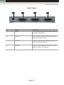
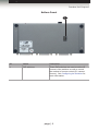
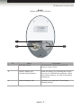
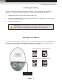
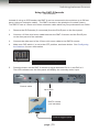
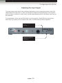
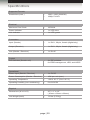
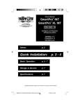
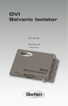
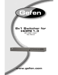
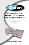
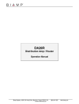
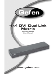
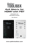
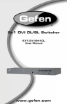
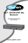
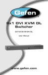
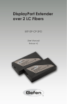
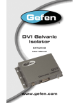
Audio
Mini
DVI
Switcher
3GSDI Embedder
EXT-MINIDVI-241N
User Manual
Release A3
Mini DVI Switcher
Important Safety Instructions
GENERAL SAFETY INFORMATION
1.
Read these instructions.
2.
Keep these instructions.
3.
Heed all warnings.
4.
Follow all instructions.
5.
Do not use this product near water.
6.
Clean only with a dry cloth.
7.
Do not block any ventilation openings. Install in accordance with the manufacturer’s
instructions.
8.
Do not install or place this product near any heat sources such as radiators, heat
registers, stoves, or other apparatus (including amplifiers) that produce heat.
9.
Do not defeat the safety purpose of the polarized or grounding-type plug. A polarized
plug has two blades with one wider than the other. A grounding type plug has two
blades and a third grounding prong. The wide blade or the third prong are provided for
your safety. If the provided plug does not fit into your outlet, consult an electrician for
replacement of the obsolete outlet.
10. Protect the power cord from being walked on or pinched particularly at plugs,
convenience receptacles, and the point where they exit from the apparatus.
11. Only use attachments/accessories specified by the manufacturer.
12. To reduce the risk of electric shock and/or damage to this product, never handle or
touch this unit or power cord if your hands are wet or damp. Do not expose this
product to rain or moisture.
13. Unplug this apparatus during lightning storms or when unused for long periods of time.
14. Refer all servicing to qualified service personnel. Servicing is required when the
apparatus has been damaged in any way, such as power-supply cord or plug is
damaged, liquid has been spilled or objects have fallen into the apparatus,
the apparatus has been exposed to rain or moisture, does not operate normally,
or has been dropped.
15. Batteries that may be included with this product and/or accessories should never be
exposed to open flame or excessive heat. Always dispose of used batteries
according to the instructions.
ii
Mini DVI Switcher
Warranty Information
Gefen warrants the equipment it manufactures to be free from defects in material and
workmanship.
If equipment fails because of such defects and Gefen is notified within two (2) years from
the date of shipment, Gefen will, at its option, repair or replace the equipment, provided
that the equipment has not been subjected to mechanical, electrical, or other abuse or
modifications. Equipment that fails under conditions other than those covered will be
repaired at the current price of parts and labor in effect at the time of repair. Such repairs
are warranted for ninety (90) days from the day of reshipment to the Buyer.
This warranty is in lieu of all other warranties expressed or implied, including without
limitation, any implied warranty or merchantability or fitness for any particular purpose, all of
which are expressly disclaimed.
1.
Proof of sale may be required in order to claim warranty.
2.
Customers outside the US are responsible for shipping charges to and from Gefen.
3.
Copper cables are limited to a 30 day warranty and cables must be in their original
condition.
The information in this manual has been carefully checked and is believed to be accurate.
However, Gefen assumes no responsibility for any inaccuracies that may be contained
in this manual. In no event will Gefen be liable for direct, indirect, special, incidental, or
consequential damages resulting from any defect or omission in this manual, even if
advised of the possibility of such damages. The technical information contained herein
regarding the features and specifications is subject to change without notice.
For the latest warranty coverage information, refer to the Warranty and Return Policy under
the Support section of the Gefen Web site at www.gefen.com.
PRODUCT REGISTRATION
Please register your product online by visiting the Register Product page under the
Support section of the Gefen Web site.
iii
Mini DVI Switcher
Contacting Gefen Technical Support
Gefen, LLC
c/o Customer Service
20600 Nordhoff St.
Chatsworth, CA 91311
Telephone:
(818) 772-9100
(800) 545-6900
Fax:
(818) 772-9120
Email:
[email protected]
Visit us on the Web:
www.gefen.com
Technical Support Hours:
8:00 AM to 5:00 PM Monday - Friday, Pacific Time
Mini DVI Switcher is a trademark of Gefen, LLC.
Important Notice
Gefen, LLC reserves the right to make changes in the hardware, packaging, and any
accompanying documentation without prior written notice.
© 2013 Gefen, LLC. All Rights Reserved.
All trademarks are the property of their respective owners.
iv
3GSDI
Mini
DVI
Audio
Switcher
Embedder
Operating Notes
This page left intentionally blank
v
Mini DVI Switcher
Features and Packing List
Features
•
Saves money on hardware and space on your desktop - there is no need to purchase
multiple displays
•
Saves time - there is no need to disconnect and reconnect equipment - everything is
always connected and accessible
•
Maintains hi-res video modes up to 1080p (HDTV) and 1920x1200 (computers)
•
Compatible with all DVI-equipped devices
•
Offers operational flexibility - Switch sources with the front panel button on the
Switcher or with the IR remote control
•
Conforms with DVI 1.0 specifications for resolutions up to 1920 x 1200
•
Easy to install and simple to operate
1080P
Packing List
The Mini DVI Switcher ships with the items listed below. If any of these items are not
present in your box when you first open it, immediately contact your dealer or Gefen.
•
•
•
•
•
1 x Mini DVI Switcher
2 x 6 ft. dual-link DVI cables (M-M)
1 x IR remote control unit
1 x 5V DC power supply
1 x Quick-Start Guide
vi
3GSDI
Mini
DVI
Audio
Switcher
Embedder
Table of Contents
01
Getting Started
Panel Layout.......................................................................................................... 2
Front Panel..................................................................................................... 2
Back Panel..................................................................................................... 3
Bottom Panel.................................................................................................. 4
IR Remote Control Unit.......................................................................................... 5
Front............................................................................................................... 5
Back............................................................................................................... 6
Installing the Battery....................................................................................... 7
Setting the IR Channel................................................................................... 7
Installation.............................................................................................................. 8
Connecting the Mini DVI Switcher.................................................................. 8
Sample Wiring Diagram................................................................................. 8
02
Operating the Mini DVI Switcher
Configuring the Switcher...................................................................................... 12
DIP Switches................................................................................................ 12
Switching between Sources................................................................................. 13
Using the Select button................................................................................ 13
Using the IR Remote Control Unit................................................................ 14
Using the RMT-2 Remote............................................................................ 15
Adjusting the Input Signal............................................................................ 16
03Appendix
Specifications....................................................................................................... 20
viii
Mini DVI Switcher
01 Getting Started
Panel Layout.......................................................................................................... 2
Front Panel..................................................................................................... 2
Back Panel..................................................................................................... 3
Bottom Panel.................................................................................................. 4
IR Remote Control Unit.......................................................................................... 5
Front............................................................................................................... 5
Back............................................................................................................... 6
Installing the Battery....................................................................................... 7
Setting the IR Channel................................................................................... 7
Installation.............................................................................................................. 8
Connecting the Mini DVI Switcher.................................................................. 8
Sample Wiring Diagram................................................................................. 8
Getting Started
Panel Layout
Front Panel
1
2
3
4
5
6
7
8
ID
Name
Description
1
Power
This LED indicator will glow bright red when
the unit is powered.
2
IR
Receives IR signals from the included IR
remote control unit.
3
Ext-IR
Connect an IR Extender (Gefen part
no. EXT-RMT-EXTIR) or RMT-2 remote
(Gefen part no. EXT-RMT-2) to this port.
See Switching between Sources for more
information.
4
1
This LED will glow bright blue when the unit
is powered and the currently selected input
is DVI In 1.
5
2
This LED will glow bright blue when the unit
is powered and the currently selected input
is DVI In 2.
6
Select
Press this button to switch between DVI
In 1 and DVI In 2. The indicator LEDs on
the front panel will indicate the currently
selected input.
7
EQ 1
Use this trimpot to adjust the output signal
when DVI In 1 is the active input.
8
EQ 2
Use this trimpot to adjust the output signal
when DVI In 2 is the active input.
page | 2
Getting Started
Sender Unit Layout
Back Panel
1
2
3
4
ID
Name
Description
1
5V DC
Connect the included 5V DC power supply to
this power receptacle.
2
DVI In 1
Connect a DVI source to this port using one
of the included DVI cables.
3
DVI In 2
Connect a DVI source to this port using one
of the included DVI cables.
4
DVI Out
Connect a DVI cable from this port to a DVI
display (or other sink device).
page | 3
Getting Started
Sender Unit Layout
Bottom Panel
1
ID
Name
Description
1
DIP switches
These DIP switches are used to set the IR
channel of the switcher as well as control
the method of remote control (IR / contact
closure). See Configuring the Switcher for
more information.
page | 4
Getting Started
IR Remote Control Unit
Front
1
2
ID
Name
Description
1
Activity indicator
This LED glows bright orange when a key
is pressed on the remote.
2
Buttons (1 - 2)
Used to select the desired input.
NOTE: If the Activity Indicator, on the IR remote control unit,
flashes quickly while holding down any one of the buttons, then this
indicates a low battery. Replace the battery as soon as possible.
page | 5
Getting Started
IR Remote Control Unit
Back
(shown with cover removed)
1
2
ID
3
Name
Description
1
DIP switch bank
Use these DIP switches to set the IR
channel of the remote.
2
Primary battery slot
(shown without battery)
Holds the battery for operating the remote.
Use only 3V CR2032-type batteries. Make
sure that the positive (+) side of the battery
is facing up.
3
Alternate battery slot
Allows for the installation of secondary
(backup) battery.
page | 6
Getting Started
IR Remote Control Unit
Installing the Battery
The IR remote control unit ships with two batteries. Only one battery is required for
operation. The second battery is a spare. Use only 3V CR2032-type batteries.
1.
Remove the back cover the IR Remote Control unit.
2.
Insert the included battery into the primary battery slot. The positive (+) side of the
battery should be facing up.
3.
Replace the back cover.
WARNING: Risk of explosion if battery is replaced by an incorrect
type. Dispose of used batteries according to the instructions.
Setting the IR Channel
In order for the included IR remote control to communicate with the Mini DVI Switcher, the
IR remote control must be set to the same channel as the matrix. See Configuring the
Switcher for instructions on setting the IR channel of the switcher.
Channel 0 (default):
Remote Channel 1:
ON
1
2
Remote Channel 2:
ON
1
Remote Channel 3:
ON
1
DIP switches
page | 7
2
2
ON
1
2
Getting Started
Installation
Page Title
Connecting the Mini DVI Switcher
1.
Connect 2 DVI sources to both DVI In 1 and DVI In 2 ports on the switcher using the
included DVI cables.
2.
Use another DVI cable to connect the display to the DVI Out port on the switcher.
3.
Connect the included 5V DC power supply to the switcher, then connect the AC power
cord to an available electrical outlet.
4.
Before operating this product, see DIP Switches for important configuration
information.
Sample Wiring Diagram
DVI CABLE
DVI Source
DVI Source
Switcher
DVI Display
EXT-MINIDVI-241N
page | 8
Mini DVI Switcher
02 Operating the Mini DVI Switcher
Configuring the Switcher...................................................................................... 12
DIP Switches................................................................................................ 12
Switching between Sources................................................................................. 13
Using the Select button................................................................................ 13
Using the IR Remote Control Unit................................................................ 14
Using the RMT-2 Remote............................................................................ 15
Adjusting the Input Signal............................................................................ 16
Operating the Mini DVI Switcher
Configuring the Switcher
DIP Switches
On the bottom panel of the Mini DVI Switcher are a bank of 4 DIP switches. Remove the
piece of colored tape to reveal the DIP switch bank. DIP switches 3 and 4 are used to set
the IR channel of the switcher. DIP switch 1 switches control between IR and the RMT-2
remote (not included). DIP switch 2 is not used.
DIP Switch
Setting
Description
1
OFF (default)
Enables the use of the RMT-2 control,
if connected. The RMT-2 uses contactclosure to toggle between inputs.
ON
Uses the IR Extender (if connected).
2
NOT USED
DIP Switch
IR channel 1
IR channel 2
IR channel 3
IR channel 4
3
OFF
(default)
OFF
ON
ON
4
OFF
(default)
ON
OFF
ON
IMPORTANT: If using an IR Extender, DIP switch 1 must be in the
ON (up) position in order for the IR Extender to function correctly.
page | 12
Operating the Mini DVI Switcher
Switching between Sources
Page Title
Using the Select button
1.
Make sure the Mini DVI Switch is powered. The Power LED should glow bright red
if the unit is properly powered.
2.
Press the Select button on the front panel to toggle between DVI In 1 and DVI In 2.
3.
The active input will be indicated on the front panel. In the example below, LED 1 is
active indicating that DVI In 1 is the selected input.
DVI In 1 is
selected
4.
Press the
Select button
Pressing the Select button, again, will toggle the input to DVI In 2. LED 2 will glow
bright blue, indicating that DVI In 2 is the active input.
DVI In 2 is
selected
page | 13
Operating the Mini DVI Switcher
Page
Title
Switching between
Sources
Using the IR Remote Control Unit
1.
Point the IR remote control at the IR sensor on the front panel of the switcher.
If an IR Extender is connected to the switcher, make sure to point the IR remote
control unit at the IR sensor on the IR Extender.
2.
The IR remote control unit provides discrete switching: Press the button on the IR
remote control unit that corresponds with the input to be selected. For example,
to select DVI In 1, press button 1 on the IR remote control unit.
LED indicates a
button was pressed
Press button 1
DVI In 1 is
selected
3.
Pressing button 2 on the IR remote control unit will select DVI In 2. LED 2 will glow
bright blue, indicating that DVI In 2 is the active input.
page | 14
Operating the Mini DVI Switcher
Switching between Sources
Using the RMT-2 Remote
(not included)
Instead of using an IR Extender, the RMT-2 can be connected to the switcher up to 50 feet
away (using an extension cable). The RMT-2 works on the principle of contact closure.
The RMT-2 uses a 3.5mm mini-mono extension cable which may be purchased from Gefen
1.
Remove the IR Extender (if connected) from the Ext-IR port on the front panel.
2.
Connect a 3.5mm mini-mono cable between the RMT-2 remote and the Ext-IR port
on the front panel of the switcher.
3.
Connect the other end of the 3.5mm mini-mono cable to the RMT-2 remote.
4.
Make sure DIP switch 1 is set to the OFF position, as shown below. See Configuring
the Switcher for more information.
DIP switch 1 in the OFF position
5.
Press the button on the RMT-2 remote to toggle between DVI In 1 and DVI In 2.
The LED indicators on the front panel will display the currently active input.
Control cable
Up to 50 ft.
RMT-2 control
(not included)
Push to toggle inputs
page | 15
Operating the Mini DVI Switcher
Configuring the Switcher
Adjusting the Input Signal
The input signal may need to be equalized depending on the length and quality of the DVI
cables that are being used. If, after connecting all equipment and powering on the system,
there is either no picture or video noise on the output display device, the signal may have to
be equalized.
For equalization, there are two EQ knobs on the front panel. Each EQ knob represents
each input. According to the length of the cable, the EQ knob should be adjusted.
Adjusts signal for
DVI In 1
Adjusts signal for
DVI In 2
page | 16
Mini DVI Switcher
03Appendix
Specifications....................................................................................................... 20
Appendix
Specifications
Supported Formats
Resolutions (max.)
•
•
1920 x 1200 (WUXGA)
1080p Full HD
Maximum Pixel Clock
•
165 MHz
Power Indicator
•
1 x LED, blue
Link Indicator
•
1 x LED, green
Input (Sender)
•
1 x DVI-I, 29-pin, female (digital only)
Output (Receiver)
•
1 x DVI-I, 29-pin, female (digital only)
Link (Sender / Receiver)
•
1 x RJ-45
•
4 x DIP switches
for EDID management, HPD, and HDCP
Power Input (Sender / Receiver)
•
1 x 5V DC
Power Consumption (Sender / Receiver)
•
10W per unit (max.)
Operating Temperature
•
+32 to 113 °F (0 to +45 °C)
Operating Humidity (non-condensing)
•
0 to 90% RH
Dimensions (W x H x D)
•
4.3” x 1” x 4.3”
(110mm x 26mm x 86mm)
Unit Weight (each)
•
1.5 lbs (0.70 kg)
Electrical
Connectors
Control
DIP Switches (Sender unit)
Operational
Physical
page | 20
Stretch it, Switch it, Split it, Control it.
Gefen’s got it. ®
20600 Nordhoff St., Chatsworth CA 91311
1-800-545-6900 818-772-9100 fax: 818-772-9120
www.gefen.com [email protected]
Pb
This product uses UL or CE listed power supplies.