1
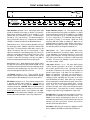
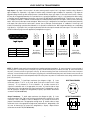
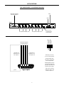
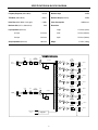
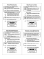
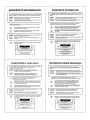
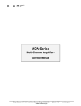
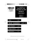
DA28R
Distribution Amp / Router
Operation Manual
Biamp Systems, 10074 S.W. Arctic Drive, Beaverton, Oregon 97005 U.S.A.
an affiliate of Rauland Borg Corp.
(503) 641-7287
www.biamp.com
blank
print update
September 7, 2005
DA28R
INTRODUCTION
TABLE OF CONTENTS
Front & Rear Panel Features
pg. 2
Logic Input & Transformers
pg. 3
Applications
Specifications & Block Diagram
Warranty
pgs. 4 & 5
pg. 6
The DA28R is a 2-in by 8-out distribution amp/router. Each input channel
accepts mic or line-level signals, and includes phantom power for condenser
microphones. All outputs are electronically balanced & floating line-level, with
600 ohm drive capability. Logic inputs allow routing of each input to specific
outputs via external contact-closures. The DA28R can operate as a flexible
2x8 distrubution amp, or as a complete 8-zone page-over-music routing
system. The DA28R carries a five-year warranty.
DA28R features include:
♦ two electronically balanced, differential mic/line inputs
♦ pad switch, trim control, & peak indicator on each input
♦ 24 volt phantom power switch on each input channel
♦ eight electronically balanced & floating line outputs
(600 ohm line output drive capability)
♦ screwdriver adjustable level control for each output
♦ sixteen logic inputs with invert function switches
(mute/assign inputs to outputs via external switches)
♦ inputs & outputs on plug-in barrier strip connectors
♦ optional input and output isolation transformers
♦ covered by Biamp Systems’ five-year warranty
♦
1
marked and UL / C-UL listed power source
FRONT & REAR PANEL FEATURES
DA28R
on
OUTPUTS
DA28R
INPUTS
BIAMP SYSTEMS
invert logic
phantom
invert logic
phantom
~
27V
50/60 Hz
Portland, Oregon
an affiliate of Rauland-Borg Corp.
level
level
level
level
level
level
level
level
trim
trim
pad
output 8
output 7
output 6
output 5
output 4
output 3
output 2
output 1
CH 1
logic inputs
CH 2
+10
12 watts
class 2 wiring
pad
+10
CH 2
CH 1
Output Connectors (Outputs 1~8): These plug-in barrier strips
provide the balanced line-level signals from Outputs 1~8. Output
isolation transformers (model IT-B) are available as a user installed
option (see Transformers on pg. 3). For balanced output, wire high
(+), low (-), and ground (d). For unbalanced output, wire high (+)
and ground (d), leaving (-) unconnected. Signal level will be
reduced by 6dB when outputs are unbalanced. Output 1~8 are
assigned signals from Channel 1 and/or Channel 2, by means of
DIP Switches & Logic Inputs (see below). From the factory, signals
from both input channels are assigned to all Outputs 1~8.
Input Connectors (Channels 1 & 2): These plug-in barrier strips
provide the balanced mic/line inputs for Channel 1 & Channel 2.
Input isolation transformers (model IT-A) are available as a user
installed option (see Transformers on pg. 3). For balanced input,
wire high (+), low (-), and ground (d). For unbalanced input, wire
high (+), and ground to both (d) & (-). Phantom power (+24VDC) is
available for condenser microphones (see DIP Switches below).
Trim (Channels 1 & 2): These screw-driver adjustable controls set
the channel gain (+24dB ~ +60dB) to compensate for different input
signal levels. For best performance, adjust these controls so the
channel +10 indicators flash only on occasional peaks. If input
signal level exceeds the normal operating range of the Trim control,
assign the corresponding channel Pad switch (see below). When
both inputs are assigned to common outputs, it may then be
necessary to reduce the Trim setting on one input, to establish a
proper level relationship (mix) between the two input signals.
Level (Outputs 1~8): These screw-driver adjustable controls
provide level adjustment for the respective outputs. Use the Level
controls individually to set the desired signal level for each sound
system or device being fed. The range of the Level controls is from
‘OFF’ (fully counter-clockwise) to a maximum of +16dB of gain (fully
clockwise). From the factory, all Output 1~8 Level controls are set
fully counter-clockwise, to ‘OFF’.
Pad (Channels 1 & 2): When depressed, these switches reduce
the signal level at the respective input channels by 40dB. Use the
Pad switches whenever signal level at the associated input channel
exceeds the normal operating range of the Trim control. Typically,
a line-level input signal will require use of the Pad.
Logic Inputs (Channels 1 & 2): This 25-pin Sub-D (female)
connector provides Logic Inputs 1~16 (on pins 1~16 respectively)
and a common ground (on pins 17~25). Logic Inputs allow signal
from Channel 1 & Channel 2 to be routed to the various outputs, via
external contact-closures. Logic Inputs 1~8 route Channel 1 to
Outputs 1~8 respectively. Logic Inputs 9~16 route Channel 2 to
Outputs 1~8 respectively. Logic Inputs perform either ‘muting’ or
‘unmuting’ functions, depending upon the position of the ‘Invert
Logic’ DIP Switches (see above). When ‘Invert Logic’ is assigned,
the associated input is normally muted at all outputs, and a contactclosure will ‘unmute’ the input at the desired output. From the
factory, ‘Invert Locic’ is not assigned, both inputs are normally
unmuted at all outputs, and a contact-closure will ‘mute’ the input at
the desired output. Logic Inputs allow a variety of input/output
routing (see Logic Inputs on pg. 3 & Applications on pgs. 4 & 5).
+10 Indicator (Channels 1 & 2): These red LEDs will light
whenever channel signal levels reach +10dB (8dB below clipping).
Use this feature to aid in adjusting the Trim controls (see above).
DIP Switches (Channels 1 & 2): These switches assign functions
to the input channels (when pushed up). Phantom turns on
+24VDC phantom power at the respective input, for use with
condenser microphones. CAUTION: Make sure phantom power is
turned off (switch down) when connecting line-level input signal.
Invert Logic reverses the operation of the respective Logic Inputs,
from ‘muting’ the associated channel at Outputs 1~8, to ‘unmuting’
the associated channel at Outputs 1~8 (see Logic Inputs below).
AC Power Cord: The power transformer provides 27 Volts AC to
the DA28R, and is detachable via a 5-pin DIN connector. The
DA28R has two internal ‘self-resetting’ fuses (there are no user
serviceable parts inside the unit). If the internal fuses blow, they will
attempt to re-set after a short period. However, this may be an
indication that the unit requires service.
On Indicator: When the power transformer is plugged in, and AC
power is applied to the DA28R, the red On indicator remains lit.
2
LOGIC INPUTS & TRANSFORMERS
14
invert logic
phantom
invert logic
phantom
25
invert logic
phantom
invert logic
phantom
1
invert logic
phantom
invert logic
phantom
13
invert logic
phantom
invert logic
phantom
Logic Inputs: Logic Inputs 1~16 are on pins 1~16, and a common ground is on pins 17~25. Logic Inputs 1~8 affect routing of Channel 1
signal to Outputs 1~8, respectively. Logic Inputs 9~16 affect routing of Channel 2 signal to Outputs 1~8, respectively. Logic Inputs are
triggered by being shorted to ground, usually by means of external switches, relays, logic outputs, or other such contact-closures. However,
they may also be triggered permanently, via a ‘hard-wired’ short to ground (see Applications on pg. 5). Logic Inputs perform either ‘muting’
or ‘unmuting’ functions, depending upon the position of the ‘Invert Logic’ DIP Switches (see diagrams below). From the factory, ‘Invert Locic’
is not assigned on Channel 1 or Channel 2, and both inputs are normally unmuted (turned on) at all outputs. Contact-closures can then be
used to ‘mute’ (turn off) either input at selected outputs. When ‘Invert Logic’ is assigned, the associated input is normally muted (turned off)
at all outputs, and contact-closures can be used to ‘unmute’ (turn on) that input at selected outputs. A combination of ‘Invert Logic’ and
normal (non-inverted) logic operation allows Channels 1 & 2 to provide an override function. With a single switch wired to two corresponding
Logic Inputs (i.e…Logic Inputs 1 & 9), one input may be muted, while the other input is unmuted at the same output. This can be extremely
effective in multi-zone, page-over-music applications (see Applications on pgs. 4).
Logic Inputs
pins 1~8
pins 9~16
pins 17~25
assign functions
ch-1 to outputs 1~8
ch-2 to outputs 1~8
common ground
Ch-1 & Ch-2
normally 'on'
(switches mute)
Ch-1 normally 'off'
(switches unmute)
Ch-2 normally 'on'
(switches mute)
Ch-1 normally 'on'
(switches mute)
Ch-2 normally 'off'
(switches unmute)
CH 1
CH 2
CH 1
CH 2
CH 1
CH 2
CH 1
CH 2
logic inputs
Ch-1 & Ch-2
normally 'off'
(switches unmute)
NOTE: The DA28R chassis must be dis-assembled before installing input/output transformers: 1) remove top panel (2 screws at bottom of
each side panel; 1 screw at top-center of rear panel). 2) remove screws from front panel (2 screws at each end). 3) remove hex-nuts from
rear panel (1 hex-nut each side of Logic Inputs connector). 4) remove mounting screws from circuit board (9 screws in front of rear panel
connectors; 2 screws behind each side of front panel). 6) gently pull circuit board forward (front panel comes forward; connectors exit rear
panel). 7) rotate front panel/circuit board upward, away from chassis (leave rear portion of circuit board in chassis, being careful not to strain
power cord connections).
Input Transformers: To install input transformers (see diagram at right): 1) locate
transformer positions T1 & T2 on the circuit board (circle areas located in front of input
connectors). T1 is for Channel 1 & T2 is for Channel 2. 2) un-solder & remove the 2
capacitors located within each of the appropriate circle areas. 3) install & solder an input
transformer at each of the appropriate circle areas (transformer pin 1, designated by a red dot,
must be inserted into the proper hole, designated by a square). Input isolation transformers
are model IT-A (P/N# 909-0010-01).
INPUT TRANSFORMERS
Output Transformers: To install output transformers (see diagram at right): 1) locate
transformer positions T101~T801 on the circuit board (rectangle areas located in front of output
connectors). T101 is for Output 1, T201 is for Output 2, etc. 2) un-solder & remove the 2
jumpers located within each of the appropriate rectangle areas. 3) install & solder an output
transformer at each of the appropriate rectangle areas (transformer pin 1, designated by a red
dot, must be inserted into the proper hole, designated by a square). Output isolation
transformers are model IT-B (P/N# 909-0019-00).
OUTPUT TRANSFORMERS
3
T1
R901
cap
T101
R902
cap
APPLICATIONS
EIGHT ZONES OF PAGE-OVER-MUSIC ROUTING
paging microphone
optional music
assign switches
background music source
1
COMPACT
2:50
DIGITAL AUDIO
zone paging switches
DA28R
OUTPUTS
DA28R
INPUTS
BIAMP SYSTEMS
invert logic
phantom
invert logic
phantom
Portland, Oregon
an affiliate of Rauland-Borg Corp.
level
level
level
level
level
level
level
level
trim
trim
pad
output 8
output 7
output 6
output 5
output 4
output 3
output 2
to equalizers/amplifiers for eight zones of page-over-music
pad
+10
CH 2
CH 1
paging mic (ch 2)
logic inputs set for
inverted operation.
CH 2
zone 8
zone 7
zone 6
zone 5
zone 4
zone 3
zone 2
zone 1
invert logic
phantom
invert logic
phantom
paging microphone
push-to-talk switches
output 1
CH 1
logic inputs
CH 2
+10
12 watts
class 2 wiring
logic inputs 9~16
mute the music
CH 1
~
27V
50/60 Hz
logic inputs 1~8
un-mute the mic
Inverted operation of the
'paging mic' logic inputs
allows the microphone
push-to-talk switches
to un-mute the mic signal
at the appropriate outputs.
13
1
25
ground
Non-inverted operation of
the 'music' logic inputs
assigns music to all outputs.
14
Music assign switches may
be added, which will mute
music at specific outputs
(music assign switches
require diode isolation).
logic inputs
4
APPLICATIONS
TWO INDEPENDENT 1x4 DISTRIBUTION AMPS
input 1
input/output assignment
via hard-wired jumpers
input 2
DA28R
OUTPUTS
INPUTS
Portland, Oregon
an affiliate of Rauland-Borg Corp.
level
level
level
level
level
level
level
level
trim
trim
pad
output 8
output 7
output 6
output 5
output 3
output 2
output 1
four outputs from input 1 (ch 1)
CH 2
CH 1
both ch 1 & ch 2
logic inputs set for
normal operation.
CH 2
input/output assignment
via hard-wired jumpers
logic inputs 9~12
mute input 2 (ch 2)
from outputs 1~4
pad
+10
invert logic
phantom
invert logic
phantom
four outputs from input 2 (ch 2)
output 4
CH 1
logic inputs
CH 2
+10
12 watts
class 2 wiring
logic inputs 5~8
mute input 1 (ch 1)
from outputs 5~8
CH 1
DA28R
BIAMP SYSTEMS
invert logic
phantom
invert logic
phantom
~
27V
50/60 Hz
Both inputs (ch 1 & ch 2)
are set for normal operation.
Normal operation allows
both inputs to be mixed and
sent to all eight outputs.
13
1
25
ground
Hard-wired jumpers are then
connected to the appropriate
logic inputs, which mute each
input from specific outputs.
14
Input 1 (ch 1) is muted at
outputs 5~8. Input 2 (ch 2)
is muted at outputs 1~4.
logic inputs
5
SPECIFICATIONS & BLOCK DIAGRAM
Frequency Response (20Hz~20kHz):
+0/-1dB
Maximum Input:
+24dBu
THD+Noise (20Hz~20kHz):
< 0.03%
Maximum Output (balanced):
+24dBu
Noise Floor (20Hz~20kHz @ unity gain):
< -75dBu
Maximum Gain (mic in to balanced out):
79dB
Power Consumption:
10 Watts max.
Dimensions:
Input Impedance (balanced):
height
1.75 inches (44mm)
mic input
4.3k ohms
width
19 inches (483mm)
line input
5.6k ohms
depth
7.5 inches (190mm)
Output Impedance (balanced):
200 ohms
Weight:
4.75 lbs. (2.16kg)
DA28R Block Diagram
+ 24V
pad
+
input 1
mic/line
com
phantom
power
input
transformer
(optional)
trim
ch 1 bus
-40dB
S
mic
preamp
level 1
output
transformer
(optional)
+ output 1
-
peak
peak
detect
S
level 2
output
transformer
(optional)
com
output 2
+
-
S
level 3
output
transformer
(optional)
com
+
-
S
level 4
output
transformer
(optional)
output 3
com
+
output 4
com
+ 24V
pad
input 2
mic/line
+
-
phantom
power
input
transformer
(optional)
S
level 5
+
trim
ch 2 bus
-40dB
mic
preamp
com
output
transformer
(optional)
peak
S
level 6
output
transformer
(optional)
+
-
peak
detect
S
level 7
output
transformer
(optional)
output 5
com
output 6
com
+
output 7
-
level 8
S
output
transformer
(optional)
com
+
-
output 8
com
logic inputs
1-16
logic input
routing control
6
WARRANTY
BIAMP SYSTEMS IS PLEASED TO EXTEND THE FOLLOWING 5-YEAR LIMITED WARRANTY TO THE
ORIGINAL PURCHASER OF THE PROFESSIONAL SOUND EQUIPMENT DESCRIBED IN THIS MANUAL
1. BIAMP Systems warrants to the original purchaser of new
products that the product will be free from defects in material
and workmanship for a period of 5 YEARS from the date of
purchase from an authorized BIAMP Systems dealer, subject to
the terms and conditions set forth below.
2. If you notify BIAMP during the warranty period that a BIAMP
Systems product fails to comply with the warranty, BIAMP
Systems will repair or replace, at BIAMP Systems' option, the
nonconforming product. As a condition to receiving the benefits
of this warranty, you must provide BIAMP Systems with
documentation that establishes that you were the original
purchaser of the products. Such evidence may consist of your
sales receipt from an authorized BIAMP Systems dealer.
Transportation and insurance charges to and from the BIAMP
Systems factory for warranty service shall be your responsibility.
3. This warranty will be VOID if the serial number has been
removed or defaced; or if the product has been altered,
subjected to damage, abuse or rental usage, repaired by any
person not authorized by BIAMP Systems to make repairs; or
installed in any manner that does not comply with BIAMP
Systems' recommendations.
4. Electro-mechanical fans, electrolytic capacitors, and normal
wear and tear of items such as paint, knobs, handles, and
covers are not covered under this warranty.
5.
THIS WARRANTY IS IN LIEU OF ALL OTHER
WARRANTIES, EXPRESS OR IMPLIED. BIAMP SYSTEMS
DISCLAIMS ALL OTHER WARRANTIES, EXPRESS OR
IMPLIED, INCLUDING, BUT NOT LIMITED TO, IMPLIED
WARRANTIES OF MERCHANTABILITY AND FITNESS FOR A
PARTICULAR PURPOSE.
6. The remedies set forth herein shall be the purchaser's sole
and exclusive remedies with respect to any defective product.
7. No agent, employee, distributor or dealer of Biamp Systems
is authorized to modify this warranty or to make additional
warranties on behalf of Biamp Systems.
statements,
representations or warranties made by any dealer do not
constitute warranties by Biamp Systems. Biamp Systems shall
not be responsible or liable for any statement, representation or
warranty made by any dealer or other person.
8. No action for breach of this warranty may be commenced
more than one year after the expiration of this warranty.
9. BIAMP SYSTEMS SHALL NOT BE LIABLE FOR SPECIAL,
INDIRECT, INCIDENTAL, OR CONSEQUENTIAL DAMAGES,
INCLUDING LOST PROFITS OR LOSS OF USE ARISING OUT
OF THE PURCHASE, SALE, OR USE OF THE PRODUCTS,
EVEN IF BIAMP SYSTEMS WAS ADVISED OF THE
POSSIBILITY OF SUCH DAMAGES.
Biamp Systems
10074 S.W. Arctic Drive
Beaverton, Oregon 97005
(503) 641-7287
585.0152.00