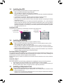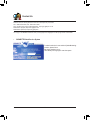
1
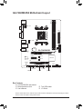
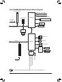
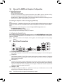
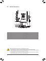
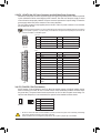
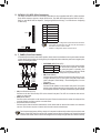
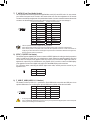
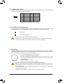
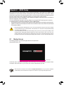
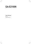
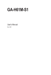
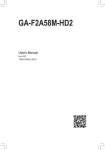
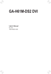
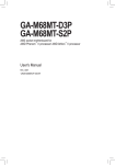
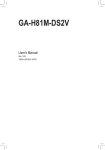
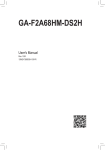
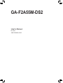
GA-F2A55M-DS2 User's Manual Rev. 3001 12ME-F255MS2-3001R Motherboard GA-F2A55M-DS2 Motherboard GA-F2A55M-DS2 Sept. 6, 2013 Sept. 6, 2013 Copyright © 2013 GIGA-BYTE TECHNOLOGY CO., LTD. All rights reserved. The trademarks mentioned in this manual are legally registered to their respective owners. Disclaimer Information in this manual is protected by copyright laws and is the property of GIGABYTE. Changes to the specifications and features in this manual may be made by GIGABYTE without prior notice. No part of this manual may be reproduced, copied, translated, transmitted, or published in any form or by any means without GIGABYTE's prior written permission. In order to assist in the use of this product, carefully read the User's Manual. For product-related information, check on our website at: http://www.gigabyte.com Identifying Your Motherboard Revision The revision number on your motherboard looks like this: "REV: X.X." For example, "REV: 1.0" means the revision of the motherboard is 1.0. Check your motherboard revision before updating motherboard BIOS, drivers, or when looking for technical information. Example: Table of Contents GA-F2A55M-DS2 Motherboard Layout............................................................................4 GA-F2A55M-DS2 Motherboard Block Diagram................................................................5 Chapter 1 Hardware Installation......................................................................................6 1-1 1-2 1-3 1-4 1-5 1-6 1-7 1-8 Installation Precautions..................................................................................... 6 Product Specifications....................................................................................... 7 Installing the APU.............................................................................................. 9 Installing the Memory........................................................................................ 9 Installing an Expansion Card............................................................................ 9 Setup of the AMD Dual Graphics Configuration.............................................. 10 Back Panel Connectors................................................................................... 10 Internal Connectors......................................................................................... 12 Chapter 2 BIOS Setup...................................................................................................17 2-1 Startup Screen................................................................................................ 17 2-2M.I.T................................................................................................................ 18 2-3 System Information......................................................................................... 21 2-4 BIOS Features................................................................................................ 22 2-5Peripherals...................................................................................................... 24 2-6 Power Management........................................................................................ 26 2-7 Save & Exit...................................................................................................... 28 Chapter 3 Appendix.......................................................................................................29 3-1 3-2 Configuring SATA Hard Drive(s)...................................................................... 29 Drivers Installation........................................................................................... 31 Regulatory Statements............................................................................................... 32 Contact Us................................................................................................................. 36 -3- KB_MS DDR3_1 DDR3_2 GA-F2A55M-DS2 Motherboard Layout VGA ATX_12V Socket FM2+ DVI ATX R_USB CPU_FAN USB_LAN AUDIO BAT Realtek® GbE LAN SATA2 2 3 GA-F2A55M-DS2 PCIEX16 iTE® Super I/O PCIEX1 M_BIOS AMD A55 B_BIOS PCI CODEC CLR_CMOS COM F_AUDIO F_USB1 SYS_FAN SPDIF_O SATA2 0 1 F_USB2 F_PANEL Box Contents 55 GA-F2A55M-DS2 motherboard 55 Motherboard driver disk 55 User's Manual 55 Two SATA cables 55 I/O Shield The box contents above are for reference only and the actual items shall depend on the product package you obtain. The box contents are subject to change without notice. -4- GA-F2A55M-DS2 Motherboard Block Diagram 1 PCI Express x16 APU CLK+/- (100 MHz) DISP CLK+/- (100 MHz) 1 PCI Express x1 DDR3 2133/1866/1600/1333 MHz AMD APU Dual Channel Memory PCIe CLK (100 MHz) x16 PCI Express Bus DVI-D x1 D-Sub x1 UMI Realtek® GbE LAN RJ45 LAN PCI Bus 8 USB 2.0/1.1 Dual BIOS AMD A55 4 SATA 3Gb/s LPC Bus PS/2 KB/Mouse S/PDIF Out PCI CLK (33 MHz) MIC (Center/Subwoofer Speaker Out) Line Out (Front Speaker Out) Line In (Rear Speaker Out) CODEC 1 PCI COM iTE® Super I/O For detailed product information/limitation(s), refer to "1-2 Product Specifications." -5- Chapter 1 Hardware Installation 1-1 Installation Precautions The motherboard contains numerous delicate electronic circuits and components which can become damaged as a result of electrostatic discharge (ESD). Prior to installation, carefully read the user's manual and follow these procedures: •• Prior to installation, make sure the chassis is suitable for the motherboard. •• Prior to installation, do not remove or break motherboard S/N (Serial Number) sticker or warranty sticker provided by your dealer. These stickers are required for warranty validation. •• Always remove the AC power by unplugging the power cord from the power outlet before installing or removing the motherboard or other hardware components. •• When connecting hardware components to the internal connectors on the motherboard, make sure they are connected tightly and securely. •• When handling the motherboard, avoid touching any metal leads or connectors. •• It is best to wear an electrostatic discharge (ESD) wrist strap when handling electronic components such as a motherboard, CPU or memory. If you do not have an ESD wrist strap, keep your hands dry and first touch a metal object to eliminate static electricity. •• Prior to installing the motherboard, please have it on top of an antistatic pad or within an electrostatic shielding container. •• Before unplugging the power supply cable from the motherboard, make sure the power supply has been turned off. •• Before turning on the power, make sure the power supply voltage has been set according to the local voltage standard. •• Before using the product, please verify that all cables and power connectors of your hardware components are connected. •• To prevent damage to the motherboard, do not allow screws to come in contact with the motherboard circuit or its components. •• Make sure there are no leftover screws or metal components placed on the motherboard or within the computer casing. •• Do not place the computer system on an uneven surface. •• Do not place the computer system in a high-temperature environment. •• Turning on the computer power during the installation process can lead to damage to system components as well as physical harm to the user. •• If you are uncertain about any installation steps or have a problem related to the use of the product, please consult a certified computer technician. -6- 1-2 Product Specifications APU FM2+ Socket: - AMD A series processors - AMD Athlon™ series processors (Go to GIGABYTE's website for the latest CPU support list.) Chipset AMD A55 Memory 2 x 1.5V DDR3 DIMM sockets supporting up to 64 GB of system memory Onboard Graphics Dual channel memory architecture Support for DDR3 2133/1866/1600/1333 MHz memory modules Support for AMD Memory Profile (AMP)/Extreme Memory Profile (XMP) memory modules (Go to GIGABYTE's website for the latest supported memory speeds and memory modules.) APU with integrated AMD Radeon™ HD 8000/7000 series graphics: - - Audio *Due to a Windows 32-bit operating system limitation, when more than 4 GB of physical memory is installed, the actual memory size displayed will be less than the size of the physical memory installed. *The maximum 64 GB of system memory can be supported using 16 GB (or above) memory modules. GIGABYTE will update the memory support list on the official website when the memory modules are available on the market. *To use the onboard graphics port, you must install an AMD APU with integrated graphics. 1 x D-Sub port, supporting a maximum resolution of 1920x1200 1 x DVI-D port, supporting a maximum resolution of 2560x1600 *Support for 2560x1600 resolution requires both a monitor and cable that support Dual Link DVI. * The DVI-D port does not support D-Sub connection by adapter. - Maximum shared memory of 2 GB Realtek® ALC887 codec High Definition Audio 2/4/5.1/7.1-channel *To configure 7.1-channel audio, you have to use an HD front panel audio module and enable the multi-channel audio feature through the audio driver. Support for S/PDIF Out LAN Realtek® GbE LAN chip (10/100/1000 Mbit) Expansion Slots 1 x PCI Express x16 slot, running at x16 (The PCI Express x16 slot conforms to PCI Express 3.0 standard.) * To support PCI Express 3.0, you must install an FM2+ APU. 1 x PCI Express x1 slot (The PCI Express x1 slot conforms to PCI Express 2.0 standard.) 1 x PCI slot Multi-Graphics Technology Storage Interface USB Internal Connectors Support for AMD Dual Graphics technology * Only A series APUs support AMD Dual Graphics. Chipset: - 4 x SATA 3Gb/s connectors - Support for RAID 0, RAID 1, RAID 10, and JBOD Chipset: -8 x USB 2.0/1.1 ports (4 ports on the back panel, 4 ports available through the internal USB headers) 1 x 24-pin ATX main power connector 1 x 8-pin ATX 12V power connector -7- Internal Connectors Back Panel Connectors 4 x SATA 3Gb/s connectors 1 x APU fan header 1 x system fan header 1 x front panel header 1 x front panel audio header 1 x S/PDIF Out header 2 x USB 2.0/1.1 headers 1 x serial port header 1 x Clear CMOS jumper 1 x PS/2 keyboard port 1 x PS/2 mouse port 1 x D-Sub port 1 x DVI-D port 4 x USB 2.0/1.1 ports 1 x RJ-45 port 3 x audio jacks (Line In, Line Out, Mic In) I/O Controller iTE® I/O Controller Chip Hardware Monitor BIOS Unique Features Bundled Software Operating System System voltage detection APU/System temperature detection APU/System fan speed detection APU overheating warning APU/System fan fail warning APU/System fan speed control *Whether the fan speed control function is supported will depend on the cooler you install. 2 x 64 Mbit flash Use of licensed AMI EFI BIOS Support for DualBIOS™ PnP 1.0a, DMI 2.0, SM BIOS 2.6, ACPI 2.0a Support for @BIOS Support for Q-Flash Support for Xpress Install Support for EasyTune * Available functions in EasyTune may differ by motherboard model. Support for Smart Recovery 2 Support for ON/OFF Charge Norton® Internet Security (OEM version) Support for Windows 8.1/8/7 32-bit/64-bit *If you plan to install Windows 8.1, please download the latest drivers from GIGABYTE's website. Support for Windows Vista/XP 32-bit *To support Windows Vista/XP 32-bit, you must install an AMD FM2 Trinity APU. Form Factor Micro ATX Form Factor; 22.5cm x 17.4cm *GIGABYTE reserves the right to make any changes to the product specifications and product-related information without prior notice. * Please visit the Support & Downloads\Utility page on GIGABYTE's website to check the supported operating system(s) for the software listed in the "Unique Features" and "Bundled Software" columns. -8- 1-3 Installing the APU Read the following guidelines before you begin to install the APU: •• Make sure that the motherboard supports the APU. (Go to GIGABYTE's website for the latest APU support list.) •• Always turn off the computer and unplug the power cord from the power outlet before installing the APU to prevent hardware damage. •• Locate the pin one of the APU. The APU cannot be inserted if oriented incorrectly. •• Apply an even and thin layer of thermal grease on the surface of the APU. •• Do not turn on the computer if the APU cooler is not installed, otherwise overheating and damage of the APU may occur. •• Set the APU host frequency in accordance with the APU specifications. It is not recommended that the system bus frequency be set beyond hardware specifications since it does not meet the standard requirements for the peripherals. If you wish to set the frequency beyond the standard specifications, please do so according to your hardware specifications including the APU, graphics card, memory, hard drive, etc. Installing the APU Locate the pin one (denoted by a small triangle) of the APU socket and the APU. A Small Triangle Marking Denotes Pin One of the Socket A Small Triangle Marking Denotes APU Pin One FM2+ Socket APU 1-4 Installing the Memory Read the following guidelines before you begin to install the memory: •• Make sure that the motherboard supports the memory. It is recommended that memory of the same capacity, brand, speed, and chips be used. (Go to GIGABYTE's website for the latest supported memory speeds and memory modules.) •• Always turn off the computer and unplug the power cord from the power outlet before installing the memory to prevent hardware damage. •• Memory modules have a foolproof design. A memory module can be installed in only one direction. If you are unable to insert the memory, switch the direction. Dual Channel Memory Configuration This motherboard provides two DDR3 memory sockets and supports Dual Channel Technology. After the memory is installed, the BIOS will automatically detect the specifications and capacity of the memory. Enabling Dual Channel memory mode will double the original memory bandwidth. The two DDR3 memory sockets are divided into two channels and each channel has one memory socket as following: Channel A: DDR3_2 Channel B: DDR3_1 Due to APU limitations, read the following guidelines before installing the memory in Dual Channel mode. 1. Dual Channel mode cannot be enabled if only one DDR3 memory module is installed. 2. When enabling Dual Channel mode with two memory modules, it is recommended that memory of the same capacity, brand, speed, and chips be used for optimum performance. 1-5 Installing an Expansion Card Read the following guidelines before you begin to install an expansion card: •• Make sure the motherboard supports the expansion card. Carefully read the manual that came with your expansion card. •• Always turn off the computer and unplug the power cord from the power outlet before installing an expansion card to prevent hardware damage. -9- 1-6 Setup of the AMD Dual Graphics Configuration A. System Requirements -- AMD A series processor -- Windows 8/7 operating system -- An AMD Dual Graphics technology-supported motherboard (with the BIOS updated to the latest version) and correct driver (make sure the onboard graphics driver version is Rev. 8.982 or above) -- An AMD Radeon™ HD 6000 series graphics card that supports AMD Dual Graphics technology (for more details, please visit AMD's official website) and correct driver B. Installing the Graphics Cards and Configuring BIOS Setup Step 1: Observe the steps in "1-5 Installing an Expansion Card" and install an AMD Dual Graphics technology-supported graphics card on the PCIEX16 slot. Plug the monitor cable into the graphics card and start up your computer. Step 2: Enter BIOS Setup to set the following items under the Peripherals\GFX Configuration menu: -- Set Integrated Graphics to Force. -- Set UMA Frame Buffer Size to 512M or above. Save the settings and exit BIOS Setup. Restart your computer. C. Configuring the Graphics Driver After installing the graphics card driver in the operating system, go to the AMD VISION Engine Control Center. Browse to Performance\AMD Radeon™ Dual Graphics and ensure the Enable AMD Radeon Dual Graphics check box is selected. (Note) Make sure the drivers for the Chipset, onboard graphics, and external graphics card are properly installed. 1-7 Back Panel Connectors PS/2 Keyboard and PS/2 Mouse Port Use the upper port (green) to connect a PS/2 mouse and the lower port (purple) to connect a PS/2 keyboard. D-Sub Port The D-Sub port supports a 15-pin D-Sub connector and supports a maximum resolution of 1920x1200 (the actual resolutions supported depend on the monitor being used). Connect a monitor that supports D-Sub connection to this port. DVI-D Port (Note) The DVI-D port conforms to the DVI-D specification and supports a maximum resolution of 2560x1600. Connect a monitor that supports DVI-D connection to this port. Please note that the actual resolutions supported are dependent on the monitor being used and support for 2560x1600 resolution requires both a monitor and cable that support Dual Link DVI. USB 2.0/1.1 Port The USB port supports the USB 2.0/1.1 specification. Use this port for USB devices such as a USB keyboard/mouse, USB printer, USB flash drive and etc. (Note) The DVI-D port does not support D-Sub connection by adapter. - 10 - RJ-45 LAN Port The Gigabit Ethernet LAN port provides Internet connection at up to 1 Gbps data rate. The following describes the states of the LAN port LEDs. Connection/ Speed LED Activity LED LAN Port Connection/Speed LED: Activity LED: State Orange Description 1 Gbps data rate State Blinking Description Data transmission or receiving is occurring Green Off 100 Mbps data rate 10 Mbps data rate Off No data transmission or receiving is occurring Line In Jack (Blue) The default line in jack. Use this audio jack for line in devices such as an optical drive, walkman, etc. Line Out Jack (Green) The default line out jack. Use this audio jack for a headphone or 2-channel speaker. This jack can be used to connect front speakers in a 4/5.1/7.1-channel audio configuration. Mic In Jack (Pink) The default Mic in jack. Microphones must be connected to this jack. To configure 7.1-channel audio, you have to use an HD front panel audio module and enable the multi-channel audio feature through the audio driver. •• When removing the cable connected to a back panel connector, first remove the cable from your device and then remove it from the motherboard. •• When removing the cable, pull it straight out from the connector. Do not rock it side to side to prevent an electrical short inside the cable connector. - 11 - 1-8 Internal Connectors 1 2 3 5 12 8 5 7 4 1) 2) 3) 4) 5) 6) ATX_12V ATX CPU_FAN SYS_FAN SATA2 0/1/2/3 F_PANEL 10 9 7) 8) 9) 10) 11) 12) 6 11 F_AUDIO SPDIF_O F_USB1/F_USB2 COM CLR_CMOS BAT Read the following guidelines before connecting external devices: •• First make sure your devices are compliant with the connectors you wish to connect. •• Before installing the devices, be sure to turn off the devices and your computer. Unplug the power cord from the power outlet to prevent damage to the devices. •• After installing the device and before turning on the computer, make sure the device cable has been securely attached to the connector on the motherboard. - 12 - 1/2)ATX_12V/ATX (2x4 12V Power Connector and 2x12 Main Power Connector) With the use of the power connector, the power supply can supply enough stable power to all the components on the motherboard. Before connecting the power connector, first make sure the power supply is turned off and all devices are properly installed. The power connector possesses a foolproof design. Connect the power supply cable to the power connector in the correct orientation. The 12V power connector mainly supplies power to the APU. If the 12V power connector is not connected, the computer will not start. To meet expansion requirements, it is recommended that a power supply that can withstand high power consumption be used (500W or greater). If a power supply is used that does not provide the required power, the result can lead to an unstable or unbootable system. 1 4 5 ATX_12V: Pin No. 1 2 3 4 8 ATX_12V Definition Pin No. GND (Only for 2x4-pin 12V) 5 GND (Only for 2x4-pin 12V) 6 GND 7 GND 8 Definition +12V (Only for 2x4-pin 12V) +12V (Only for 2x4-pin 12V) +12V +12V Definition Pin No. 3.3V 13 3.3V 14 GND 15 +5V 16 GND 17 +5V 18 GND 19 Power Good 20 5VSB (stand by +5V) 21 +12V 22 +12V (Only for 2x12-pin 23 ATX) 3.3V (Only for 2x12-pin 24 ATX) Definition 3.3V -12V GND PS_ON (soft On/Off) GND GND GND -5V +5V +5V +5V (Only for 2x12-pin ATX) ATX: 12 24 1 13 Pin No. 1 2 3 4 5 6 7 8 9 10 11 12 ATX GND (Only for 2x12-pin ATX) 3/4) CPU_FAN/SYS_FAN (Fan Headers) All fan headers on this motherboard are 4-pin. Most fan headers possess a foolproof insertion design. When connecting a fan cable, be sure to connect it in the correct orientation (the black connector wire is the ground wire). The speed control function requires the use of a fan with fan speed control design. For optimum heat dissipation, it is recommended that a system fan be installed inside the chassis. 1 1 CPU_FAN SYS_FAN Pin No. 1 2 3 4 Definition GND +12V Sense Speed Control •• Be sure to connect fan cables to the fan headers to prevent your APU and system from overheating. Overheating may result in damage to the APU or the system may hang. •• These fan headers are not configuration jumper blocks. Do not place a jumper cap on the headers. - 13 - DEBUG PORT 5) SATA2 0/1/2/3 (SATA 3Gb/s Connectors) The SATA connectors conform to SATA 3Gb/s standard and are compatible with SATA 1.5Gb/s standard. Each SATA connector supports a single SATA device. The AMD A55 Chipset supports RAID 0, RAID 1, DEBUG DEBUG RAID 10, and JBOD. Refer toPORT Chapter 3, "Configuring SATA Hard Drive(s)," for instructions on configuring PORT a RAID array. Pin No. 1 2 3 4 5 6 7 1 U 1 4 S 5 2 3 B S_ B 3 S 2 SATA2 Definition GND TXP TXN GND RXN RXP GND 7 •• A RAID 0 or RAID 1 configuration requires at least two hard drives. If more than two hard drives are to be used, the total number of hard drives must be an even number. •• A RAID 10 configuration requires four hard drives. SATA2 0 1 1 7 3 _ _ _S B_ B SS S S - 14 - 1 2 3 4 U 1 2 3 S 1 1 B SS 1 The front panel design may differ by chassis. A front panel module mainly consists of power switch, reset switch, power LED, hard drive activity LED, speaker and etc. When connecting your chassis front panel module to this header, make sure the wire assignments and the pin assignments are matched correctly. F_ U F_USB3 F S_ _ B _ S S B_ B SPEAK- SPEAK+ PLED+ PLEDPW+ PW- HD+ HDRESRES+ CICI+ F_ PWR_LED+ PWR_LEDPWR_LED- 1 2 3 4 1 2 3 4 •• 1 2 3 •• 1 •• 1 2 3 F_ _ B Connect the power switch, reset switch, speaker, chassis intrusion switch/sensor and system status indicator on the chassis to this header according to the pin assignments below. Note the positive and negative pins before connecting the cables. Power LED Power Switch Speaker •• PLED/PWR_LED (Power LED): Connects to the power status indicator System Status LED on the chassis front panel. The LED is S0 On on when the system is operating. The S3/S4/S5 Off LED is off when the system is in S3/S4 sleep state or powered off (S5). 2 20 •• PW (Power Switch): 1 19 Connects to the power switch on the chassis front panel. You may configure the way to turn off your system using the power switch (refer to Chapter 2, "BIOS Setup," "Power Management," for more information). •• SPEAK (Speaker): Reset Hard Drive Power LED Activity LED Switch Connects to the speaker on the chassis front panel. The system Chassis Intrusion Header reports system startup status by issuing a beep code. One single short beep will be heard if no problem is detected at system startup. HD (Hard Drive Activity LED): Connects to the hard drive activity LED on the chassis front panel. The LED is on when the hard drive is reading or writing data. RES (Reset Switch): Connects to the reset switch on the chassis front panel. Press the reset switch to restart the computer if the computer freezes and fails to perform a normal restart. 1 2 3 CI (Chassis Intrusion Header): Connects to the chassis intrusion switch/sensor on the chassis that can detect if the chassis cover has been removed. This function requires a chassis with a chassis intrusion switch/sensor. 1 2 3 4 _ U _ B 6) F_PANEL (Front Panel Header) 7) F_AUDIO (Front Panel Audio Header) The front panel audio header supports Intel High Definition audio (HD) and AC'97 audio. You may connect your chassis front panel audio module to this header. Make sure the wire assignments of the module connector match the pin assignments of the motherboard header. Incorrect connection between the module connector and the motherboard header will make the device unable to work or even damage it. 9 10 1 2 For HD Front Panel Audio: Pin No. Definition 1 MIC2_L 2 GND 3 MIC2_R 4 -ACZ_DET 5 LINE2_R 6 GND 7 FAUDIO_JD 8 No Pin 9 LINE2_L 10 GND For AC'97 Front Panel Audio: Pin No. Definition 1 MIC 2 GND 3 MIC Power 4 NC 5 Line Out (R) 6 NC 7 NC 8 No Pin 9 Line Out (L) 10 NC •• The front panel audio header supports HD audio by default. •• Audio signals will be present on both of the front and back panel audio connections simultaneously. •• Some chassis provide a front panel audio module that has separated connectors on each wire instead of a single plug. For information about connecting the front panel audio module that has different wire assignments, please contact the chassis manufacturer. 8) SPDIF_O (S/PDIF Out Header) This header supports digital S/PDIF Out and connects a S/PDIF digital audio cable (provided by expansion cards) for digital audio output from your motherboard to certain expansion cards like graphics cards and sound cards. For example, some graphics cards may require you to use a S/PDIF digital audio cable for digital audio output from your motherboard to your graphics card if you wish to connect an HDMI display to the graphics card and have digital audio output from the HDMI display at the same time. For information about connecting the S/PDIF digital audio cable, carefully read the manual for your expansion card. Pin No. 1 2 1 Definition SPDIFO GND 9) F_USB1/F_USB2 (USB 2.0/1.1 Headers) The headers conform to USB 2.0/1.1 specification. Each USB header can provide two USB ports via an optional USB bracket. For purchasing the optional USB bracket, please contact the local dealer. 9 10 1 2 Pin No. 1 2 3 4 5 Definition Power (5V) Power (5V) USB DXUSB DYUSB DX+ Pin No. 6 7 8 9 10 Definition USB DY+ GND GND No Pin NC •• Do not plug the IEEE 1394 bracket (2x5-pin) cable into the USB header. •• Prior to installing the USB bracket, be sure to turn off your computer and unplug the power cord from the power outlet to prevent damage to the USB bracket. - 15 - 10) COM (Serial Port Header) The COM header can provide one serial port via an optional COM port cable. For purchasing the optional COM port cable, please contact the local dealer. 1 2 9 10 Pin No. 1 2 3 4 5 Definition NDCDNSIN NSOUT NDTRGND Pin No. 6 7 8 9 10 Definition NDSRNRTSNCTSNRINo Pin 11) CLR_CMOS (Clear CMOS Jumper) Use this jumper to clear the BIOS configuration and reset the CMOS values to factory defaults. To clear the CMOS values, use a metal object like a screwdriver to touch the two pins for a few seconds. Open: Normal Short: Clear CMOS Values •• Always turn off your computer before clearing the CMOS values. •• After system restart, go to BIOS Setup to load factory defaults (select Load Optimized Defaults) or manually configure the BIOS settings (refer to Chapter 2, "BIOS Setup," for BIOS configurations). 12) BAT (Battery) The battery provides power to keep the values (such as BIOS configurations, date, and time information) in the CMOS when the computer is turned off. Replace the battery when the battery voltage drops to a low level, or the CMOS values may not be accurate or may be lost. •• •• •• •• •• You may clear the CMOS values by removing the battery: 1. Turn off your computer and unplug the power cord. 2. Gently remove the battery from the battery holder and wait for one minute. (Or use a metal object like a screwdriver to touch the positive and negative terminals of the battery holder, making them short for 5 seconds.) 3. Replace the battery. 4. Plug in the power cord and restart your computer. Always turn off your computer and unplug the power cord before replacing the battery. Replace the battery with an equivalent one. Danger of explosion if the battery is replaced with an incorrect model. Contact the place of purchase or local dealer if you are not able to replace the battery by yourself or uncertain about the battery model. When installing the battery, note the orientation of the positive side (+) and the negative side (-) of the battery (the positive side should face up). Used batteries must be handled in accordance with local environmental regulations. - 16 - Chapter 2 BIOS Setup BIOS (Basic Input and Output System) records hardware parameters of the system in the CMOS on the motherboard. Its major functions include conducting the Power-On Self-Test (POST) during system startup, saving system parameters and loading operating system, etc. BIOS includes a BIOS Setup program that allows the user to modify basic system configuration settings or to activate certain system features. When the power is turned off, the battery on the motherboard supplies the necessary power to the CMOS to keep the configuration values in the CMOS. To access the BIOS Setup program, press the <Delete> key during the POST when the power is turned on. To upgrade the BIOS, use either the GIGABYTE Q-Flash or @BIOS utility. •• Q-Flash allows the user to quickly and easily upgrade or back up BIOS without entering the operating system. •• @BIOS is a Windows-based utility that searches and downloads the latest version of BIOS from the Internet and updates the BIOS. •• Because BIOS flashing is potentially risky, if you do not encounter problems using the current version of BIOS, it is recommended that you not flash the BIOS. To flash the BIOS, do it with caution. Inadequate BIOS flashing may result in system malfunction. •• It is recommended that you not alter the default settings (unless you need to) to prevent system instability or other unexpected results. Inadequately altering the settings may result in system's failure to boot. If this occurs, try to clear the CMOS values and reset the board to default values. (Refer to the "Load Optimized Defaults" section in this chapter or introductions of the battery/clear CMOS jumper in Chapter 1 for how to clear the CMOS values.) 2-1 Startup Screen The following startup Logo screen will appear when the computer boots. (Sample BIOS Version: E3) Function Keys On the main menu of the BIOS Setup program, press arrow keys to move among the items and press <Enter> to accept or enter a sub-menu. Or you can use your mouse to select the item you want. •• When the system is not stable as usual, select the Load Optimized Defaults item to set your system to its defaults. •• The BIOS Setup menus described in this chapter are for reference only and may differ by BIOS version. - 17 - 2-2M.I.T. This section provides information on the BIOS version, CPU base clock, CPU frequency, memory frequency, total memory size, CPU temperature, Vcore, and memory voltage. Whether the system will work stably with the overclock/overvoltage settings you made is dependent on your overall system configurations. Incorrectly doing overclock/overvoltage may result in damage to CPU, chipset, or memory and reduce the useful life of these components. This page is for advanced users only and we recommend you not to alter the default settings to prevent system instability or other unexpected results. (Inadequately altering the settings may result in system's failure to boot. If this occurs, clear the CMOS values and reset the board to default values.) `` M.I.T. Current Status This screen provides information on CPU/memory frequencies/parameters. `` Advanced Frequency Settings && BCLK/PCIe Clock Control Allows you to manually set the CPU base clock and PCIe bus frequency in 1 MHz increments. (Default: Auto) Important: It is highly recommended that the CPU frequency be set in accordance with the CPU specifications. && NB Clock (Mhz) Allows you to manually set the CPU North Bridge frequency. The adjustable range is from 800 MHz to 6000 MHz. Allows you to set the onboard graphics clock. The adjustable range is from 300 MHz to 2000 MHz. && Processor Graphics Clock && CPU Clock Ratio Allows you to alter the clock ratio for the installed CPU. The adjustable range is dependent on the CPU being installed. && CPU Frequency Displays the current operating CPU frequency. `` Advanced CPU Core Features && CPU Clock Ratio, CPU Frequency The settings above are synchronous to those under the same items on the Advanced Frequency Settings menu. - 18 - && Core Performance Boost (Note 1) Allows you to determine whether to enable the Core Performance Boost (CPB) technology, a CPU performance-boost technology. (Default: Auto) && Turbo CPB (Note 1) Allows you to determine whether to improve CPU performance. (Default: Disabled) Allows you alter the ratio for the CPB. The adjustable range is dependent on the CPU being installed. (Default: Auto) && CPB Ratio (Note 1) && Cool&Quiet Enabled Lets the AMD Cool'n'Quiet driver dynamically adjust the CPU clock and VID to reduce heat output from your computer and its power consumption. (Default) Disabled Disables this function. && SVM Mode Virtualization enhanced by Virtualization Technology will allow a platform to run multiple operating systems and applications in independent partitions. With virtualization, one computer system can function as multiple virtual systems. (Default: Enabled) && C6 Mode Allows you to determine whether to let the CPU enter C6 mode in system halt state. When enabled, the CPU core frequency will be reduced during system halt state to decrease power consumption. The C6 state is a more enhanced power-saving state than C1. (Default: Enabled) && CPU Core Control Allows you to determine whether to manually enable/disable CPU cores. Automatic mode allows the BIOS to enable all CPU cores (number of cores available depends on the CPU being used). (Default: Automatic mode) && APM Enables or disables Application Power Management. (Default: Enabled) && Extreme Memory Profile (X.M.P.) (Note 2) Allows the BIOS to read the SPD data on XMP memory module(s) to enhance memory performance when enabled. Disabled Disables this function. (Default) Profile1 Uses Profile 1 settings. (Note 2) Profile2 Uses Profile 2 settings. && AMD Memory Profile (A.M.P.) (Note 2) Allows the BIOS to read the SPD data on AMP memory module(s) to enhance memory performance when enabled. (Default: Disabled) && System Memory Multiplier Allows you to set the system memory multiplier. Auto sets memory multiplier according to memory SPD data. (Default: Auto) && Memory Frequency (MHz) This value is automatically adjusted according to the BCLK/PCIe Clock Control and System Memory Multiplier settings. `` Advanced Memory Settings && Extreme Memory Profile (X.M.P.) (Note 2), System Memory Multiplier, Memory Frequency(MHz) The settings above are synchronous to those under the same items on the Advanced Frequency Settings menu. (Note 1) This item is present only when you install a CPU that supports this feature. (Note 2) This item is present only when you install a CPU and a memory module that support this feature. - 19 - && DRAM Timing Selectable Quick and Expert allows the memory timing settings below to be configurable. Options are: Auto (default), Quick, Expert. && Profile DDR Voltage When using a non-XMP memory module or Extreme Memory Profile (X.M.P.) is set to Disabled, this item will display as 1.50V. When Extreme Memory Profile (X.M.P.) is set to Profile1 or Profile2, this item will display the value based on the SPD data on the XMP memory. && Profile VTT Voltage The value displayed here is dependent on the CPU being used. && Rank Interleaving Enables or disables memory rank interleaving. Enabled allows the system to simultaneously access different ranks of the memory to increase memory performance and stability. (Default: Enabled) && Channel Interleaving Enables or disables memory channel interleaving. Enabled allows the system to simultaneously access different channels of the memory to increase memory performance and stability. (Default: Enabled) `` Channel A/B Timing Settings This sub-menu provides memory timing settings for each channel of memory. The respective timing setting screens are configurable only when DRAM Timing Selectable is set to Quick or Expert.Note: Your system may become unstable or fail to boot after you make changes on the memory timings. If this occurs, please reset the board to default values by loading optimized defaults or clearing the CMOS values. `` Advanced Voltage Settings This sub-menu allows you to set CPU, chipset and memory voltages. `` PC Health Status && Reset Case Open Status Disabled Keeps or clears the record of previous chassis intrusion status. (Default) Enabled Clears the record of previous chassis intrusion status and the Case Open field will show "No" at next boot. && Case Open Displays the detection status of the chassis intrusion detection device attached to the motherboard CI header. If the system chassis cover is removed, this field will show "Yes", otherwise it will show "No". To clear the chassis intrusion status record, set Reset Case Open Status to Enabled, save the settings to the CMOS, and then restart your system. && CPU Vcore/DRAM Voltage/+3.3V/+5V/+12V Displays the current system voltages. Displays current CPU/system temperature. Displays current CPU/system fan speeds. Sets the warning threshold for CPU temperature. When CPU temperature exceeds the threshold, BIOS will emit warning sound. Options are: Disabled (default), 60oC/140oF, 70oC/158oF, 80oC/176oF, 90oC/194oF. && CPU/System Temperature && CPU/System Fan Speed && CPU Warning Temperature && CPU/System Fan Fail Warning Allows the system to emit warning sound if the fan is not connected or fails.Check the fan condition or fan connection when this occurs. (Default: Disabled) && CPU Fan Speed Control Allows you to determine whether to enable the fan speed control function and adjust the fan speed. Normal Allows the fan to run at different speeds according to the CPU temperature. You can adjust the fan speed with EasyTune based on your system requirements. (Default) - 20 - Silent Allows the fan to run at slow speeds. Manual Allows you to control the fan speed under the Slope PWM item. Disabled Allows the fan to run at full speeds. && Slope PWM Allows you to control the fan speed. This item is configurable only when CPU Fan Speed Control is set to Manual. Options are: 0.75 PWM value /oC ~ 2.50 PWM value /oC. && System Fan Speed Control Allows you to determine whether to enable the fan speed control function and adjust the fan speed. NormalAllows the fan to run at different speeds according to the system temperature. You can adjust the fan speed with EasyTune based on your system requirements. (Default) Silent Allows the fan to run at slow speeds. Manual Allows you to control the fan speed under the Slope PWM item. Disabled Allows the fan to run at full speeds. && Slope PWM Allows you to control the fan speed. This item is configurable only when System Fan Speed Control is set to Manual. Options are: 0.75 PWM value /oC ~ 2.50 PWM value /oC. 2-3 System Information This section provides information on your motherboard model and BIOS version. You can also select the default language used by the BIOS and manually set the system time. && System Language Selects the default language used by the BIOS. Sets the system date. The date format is week (read-only), month, date, and year. Use <Enter> to switch between the Month, Date, and Year fields and use the <Page Up> or <Page Down> key to set the desired value. && System Date && System Time Sets the system time. The time format is hour, minute, and second. For example, 1 p.m. is 13:0:0. Use <Enter> to switch between the Hour, Minute, and Second fields and use the <Page Up> or <Page Down> key to set the desired value. - 21 - && Access Level Displays the current access level depending on the type of password protection used. (If no password is set, the default will display as Administrator.) The Administrator level allows you to make changes to all BIOS settings; the User level only allows you to make changes to certain BIOS settings but not all. 2-4 BIOS Features && Boot Option Priorities Specifies the overall boot order from the available devices. For example, you can set hard drive as the first priority (Boot Option #1) and DVD ROM drive as the second priority (Boot Option #2). The list only displays the device with the highest priority for a specific type. For example, only hard drive defined as the first priority on the Hard Drive BBS Priorities submenu will be presented here. Removable storage devices that support GPT format will be prefixed with "UEFI:" string on the boot device list. To boot from an operating system that supports GPT partitioning, select the device prefixed with "UEFI:" string. Or if you want to install an operating system that supports GPT partitioning such as Windows 7 64-bit, select the optical drive that contains the Windows 7 64-bit installation disk and is prefixed with "UEFI:" string. && Hard Drive/CD/DVD ROM Drive/Floppy Drive/Network Device BBS Priorities Specifies the boot order for a specific device type, such as hard drives, optical drives, floppy disk drives, and devices that support Boot from LAN function, etc. Press <Enter> on this item to enter the submenu that presents the devices of the same type that are connected. This item is present only if at least one device for this type is installed. && Bootup NumLock State Enables or disables Numlock feature on the numeric keypad of the keyboard after the POST. (Default: Enabled) && Security Option Specifies whether a password is required every time the system boots, or only when you enter BIOS Setup. After configuring this item, set the password(s) under the Administrator Password/User Password item. Setup A password is only required for entering the BIOS Setup program. System A password is required for booting the system and for entering the BIOS Setup program. (Default) - 22 - && Full Screen LOGO Show Allows you to determine whether to display the GIGABYTE Logo at system startup. Disabled skips the GIGABYTE Logo when the system starts up. (Default: Enabled) && OS Type Allows you to select the operating system to be installed. (Default: Other OS) Enables or disables UEFI CSM (Compatibility Support Module) to support a legacy PC boot process. Always Enables UEFI CSM. (Default) Never Disables UEFI CSM and supports UEFI BIOS boot process only. This item is configurable only when OS Type is set to Windows 8. && CSM Support && Boot Mode Selection Allows you to select which type of operating system to boot. UEFI and LegacyAllows booting from operating systems that support legacy option ROM or UEFI option ROM. (Default) Legacy Only Allows booting from operating systems that only support legacy Option ROM. UEFI Only Allows booting from operating systems that only support UEFI Option ROM. This item is configurable only when CSM Support is set to Always. Allows you to select whether to enable the legacy option ROM for the LAN controller. (Default: Disabled) This item is configurable only when CSM Support is set to Always. Allows you to select whether to enable the UEFI or legacy option ROM for the storage device controller. Disabled Disables option ROM. Legacy Only Enables legacy option ROM only. (Default) UEFI Only Enables UEFI option ROM only. Legacy First Enables legacy option ROM first. UEFI First Enables UEFI option ROM first. This item is configurable only when CSM Support is set to Always. && LAN PXE Boot Option ROM && Storage Boot Option Control && Other PCI Device ROM Priority Allows you to select whether to enable the UEFI or Legacy option ROM for the PCI device controller other than the LAN, storage device, and graphics controllers. Legacy OpROM Enables legacy option ROM only. UEFI OpROM Enables UEFI option ROM only. (Default) && Network stack Disables or enables booting from the network to install a GPT format OS, such as installing the OS from the Windows Deployment Services server. (Default: Disable Link) && Ipv4 PXE Support Enables or disables IPv4 PXE Support. This item is configurable only when Network stack is enabled. Enables or disables IPv6 PXE Support. This item is configurable only when Network stack is enabled. Allows you to configure an administrator password. Press <Enter> on this item, type the password, and then press <Enter>. You will be requested to confirm the password. Type the password again and press <Enter>. You must enter the administrator password (or user password) at system startup and when entering BIOS Setup. Differing from the user password, the administrator password allows you to make changes to all BIOS settings. && Ipv6 PXE Support && Administrator Password - 23 - && User Password Allows you to configure a user password. Press <Enter> on this item, type the password, and then press <Enter>. You will be requested to confirm the password. Type the password again and press <Enter>. You must enter the administrator password (or user password) at system startup and when entering BIOS Setup. However, the user password only allows you to make changes to certain BIOS settings but not all. To cancel the password, press <Enter> on the password item and when requested for the password, enter the correct one first. When prompted for a new password, press <Enter> without entering any password. Press <Enter> again when prompted to confirm. 2-5Peripherals && IOMMU Enables or disables AMD IOMMU support. (Default: Enabled) Enables or disables the integrated SATA controllers. (Default: Enabled) Enables or disables RAID for the SATA controllers integrated in the AMD Chipset or configures the SATA controllers to AHCI mode. Native IDE Configures the SATA controller to IDE mode. RAID Enables RAID for the SATA controller. AHCI Configures the SATA controllers to AHCI mode. Advanced Host Controller Interface (AHCI) is an interface specification that allows the storage driver to enable advanced Serial ATA features such as Native Command Queuing and hot plug. (Default) && OnChip SATA Channel && OnChip SATA Type && OnChip USB Controller Enables or disables the integrated USB controller. (Default: Enabled) Enables or disables the onboard audio function. (Default: Enabled) If you wish to install a 3rd party add-in audio card instead of using the onboard audio, set this item to Disabled. && HD Audio Azalia Device - 24 - && Onboard LAN Controller Enables or disables the onboard LAN function. (Default: Enabled) If you wish to install a 3rd party add-in network card instead of using the onboard LAN, set this item to Disabled. && Legacy USB Support Allows USB keyboard/mouse to be used in MS-DOS. (Default: Enabled) Determines whether to enable EHCI Hand-off feature for an operating system without EHCI Hand-off support. (Default: Disabled) && EHCI Hand-off && Port 60/64 Emulation Enables or disables emulation of I/O ports 64h and 60h. This should be enabled for full legacy support for USB keyboards/mice in MS-DOS or in operating system that does not natively support USB devices. (Default: Disabled) && USB Storage Devices Displays a list of connected USB mass storage devices. This item appears only when a USB storage device is installed. `` GFX Configuration && Primary Video Device Specifies the first initiation of the monitor display from the installed PCI Express graphics card or the onboard graphics. IGD Video Sets the onboard graphics as the first display. NB PCIe Slot VideoSets the PCI Express graphics card on the PCI Express slot controlled by the North Bridge as the first display. (Default) && Integrated Graphics Enables or disables the onboard graphics function. AutoThe BIOS will automatically enable or disable the onboard graphics depending on the graphics card being installed. (Default) Disabled Disables the onboard graphics. Force Always activates the onboard graphics, whether or not a PCI Express card is installed. && UMA Frame Buffer Size This item is configurable only when Integrated Graphics is set to Force. Frame buffer size is the total amount of system memory allocated solely for the onboard graphics controller. MS-DOS, for example, will use only this memory for display. Options are: Auto (default), 256M, 512M, 1G, 2G. `` ATA Port Information This section provides information on the device connected to each SATA port controlled by AMD Chipset. `` SATA Configuration && PORT0 Hot Plug~PORT3 Hot Plug Enables or disable the hot plug capability for each SATA port. (Default: Disabled) Enables or disables each SATA port. (Default: Enabled) && SATA Power on PORT0~SATA Power on PORT3 `` Super IO Configuration This section provides information on the super I/O chip and allows you to configure the serial port. Enables or disables the onboard serial port. (Default: Enabled) && Serial Port A - 25 - 2-6 Power Management && Resume by Alarm Determines whether to power on the system at a desired time. (Default: Disabled) If enabled, set the date and time as following: Wake up day: Turn on the system at a specific time on each day or on a specific day in a month. Wake up hour/minute/second: Set the time at which the system will be powered on automatically. Note: When using this function, avoid inadequate shutdown from the operating system or removal of the AC power, or the settings may not be effective. && HPET Timer (Note) Enables or disables High Precision Event Timer (HPET) for Windows 8/7/Vista operating system. (Default: Enabled) && Soft-Off by PWR-BTTN Configures the way to turn off the computer in MS-DOS mode using the power button. Instant-Off Press the power button and then the system will be turned off instantly. (Default) Delay 4 SecPress and hold the power button for 4 seconds to turn off the system. If the power button is pressed for less than 4 seconds, the system will enter suspend mode. && AC BACK Determines the state of the system after the return of power from an AC power loss. Memory The system returns to its last known awake state upon the return of the AC power. Always On The system is turned on upon the return of the AC power. Always OffThe system stays off upon the return of the AC power. (Default) && Power On By Keyboard Allows the system to be turned on by a PS/2 keyboard wake-up event. Note: To use this function, you need an ATX power supply providing at least 1A on the +5VSB lead. Disabled Disables this function. (Default) Password Set a password with 1~5 characters to turn on the system. Keyboard 98 Press POWER button on the Windows 98 keyboard to turn on the system. Any Key Press any key to turn on the system. (Note) Supported on Windows 8/7/Vista operating system only. - 26 - && Power On Password Set the password when Power On By Keyboard is set to Password. Press <Enter> on this item and set a password with up to 5 characters and then press <Enter> to accept. To turn on the system, enter the password and press <Enter>. Note: To cancel the password, press <Enter> on this item. When prompted for the password, press <Enter> again without entering the password to clear the password settings. && Power On By Mouse Allows the system to be turned on by a PS/2 mouse wake-up event. Note: To use this function, you need an ATX power supply providing at least 1A on the +5VSB lead. Disabled Disables this function. (Default) Move Move the mouse to turn on the system. Double Click Double click on left button on the mouse to turn on the system. && ErP Determines whether to let the system consume least power in S5 (shutdown) state. (Default: Disabled) Note: When this item is set to Enabled, the following functions will become unavailable: PME event wake up, power on by mouse, power on by keyboard, and wake on LAN. - 27 - 2-7 Save & Exit && Save & Exit Setup Press <Enter> on this item and select Yes. This saves the changes to the CMOS and exits the BIOS Setup program. Select No or press <Esc> to return to the BIOS Setup Main Menu. && Exit Without Saving Press <Enter> on this item and select Yes. This exits the BIOS Setup without saving the changes made in BIOS Setup to the CMOS. Select No or press <Esc> to return to the BIOS Setup Main Menu. && Load Optimized Defaults Press <Enter> on this item and select Yes to load the optimal BIOS default settings. The BIOS defaults settings help the system to operate in optimum state. Always load the Optimized defaults after updating the BIOS or after clearing the CMOS values. && Boot Override Allows you to select a device to boot immediately. Press <Enter> on the device you select and select Yes to confirm. Your system will restart automatically and boot from that device. && Save Profiles This function allows you to save the current BIOS settings to a profile. You can create up to 8 profiles and save as Setup Profile 1~ Setup Profile 8. Press <Enter> to complete. Or you can select Select File in HDD/USB/FDD to save the profile to your storage device. && Load Profiles If your system becomes unstable and you have loaded the BIOS default settings, you can use this function to load the BIOS settings from a profile created before, without the hassles of reconfiguring the BIOS settings. First select the profile you wish to load and then press <Enter> to complete. You can select Select File in HDD/USB/FDD to input the profile previously created from your storage device or load the profile automatically created by the BIOS, such as reverting the BIOS settings to the last settings that worked properly (last known good record). - 28 - Chapter 3 Appendix 3-1 Configuring SATA Hard Drive(s) Before you begin •• At least two SATA hard drives (to ensure optimal performance, it is recommended that you use two hard drives with identical model and capacity). If you do not want to create RAID, you may prepare only one hard drive. •• Windows 8/7 (32-bit/64-bit), Vista/XP (32-bit) setup disk. •• Motherboard driver disk. •• A USB flash drive. •• A USB floppy disk drive (needed during Windows XP installation). •• An empty formatted floppy disk (needed during Windows XP installation). Configuring the Onboard SATA Controller A. Installing SATA hard drive(s) in your computer Attach one end of the SATA signal cable to the rear of the SATA hard drive and the other end to available SATA port on the motherboard. Then connect the power connector from your power supply to the hard drive. B. Configuring SATA controller mode in BIOS Setup Make sure to configure the SATA controller mode correctly in system BIOS Setup. For the BIOS Setup menus, refer to Chapter 2, "BIOS Setup," "Integrated Peripherals." Steps: 1. Turn on your computer and press <Delete> to enter BIOS Setup during the POST (Power-On Self-Test). Ensure OnChip SATA Channel is enabled under Peripherals. Set OnChip SATA Type to RAID. 2. If you want to configure UEFI RAID, follow the steps in "C-1." To enter the legacy RAID ROM, save the settings and exit BIOS Setup. Refer to "C-2" for more information. The BIOS Setup menus described in this section may differ from the exact settings for your motherboard. The actual BIOS Setup menu options you will see shall depend on the motherboard you have and the BIOS version. C-1. UEFI RAID Configuration This mode supports Windows 8 64-bit installation only. Create a RAID Array Step 1: In BIOS Setup, go to BIOS Features and set OS Type to Windows 8 and CSM Support to Never. Save the changes and exit BIOS Setup. Step 2: Restart your computer and press <F12> to enter the boot device configuration menu. Use the up or down arrow key to select UEFI: Built-in EFI Shell. Press <Enter> to access. Follow the steps below and enter the commands to access the RAID setup utility. 1. Enter drvcfg at Shell and press <Enter>: Shell> drvcfg 2. When Drv [XX] Ctrl [XX] Lang [eng] appears, enter the following commands at Shell again: Shell> drvcfg -s XX XX XXs are the values shown in the brackets after Drv and Ctrl above, which may vary by hard drives. Then press <Enter> to enter the RAID setup utility. Step 3: The Main Menu is the first screen when you enter the BIOS RAID Setup utility. Use the up or down arrow key to select Logical Drive Main Menu and press <Enter>. - 29 - Step 4: To create an array, press <Enter> on Logical Drive Create Menu. Step 5: Usable hard drives are listed on the Logical Drive Create Menu. Use the up or down arrow key to select the hard drive to be included in the array and press the <Space> key. The selected hard drives will be marked with [X]. Then move to Basic Setting and press <Enter>. Step 6: Use the up or down arrow key to move to and configure each required item in sequence. After completing, press <Enter> on Start To Create. When the message "Are You Sure To Create Logical Drive?" appears, press <Enter> to begin creating the RAID array or <Esc> to cancel. When completed, a message which says "Successful To Create Logical Drive" will appear. Press <Enter> to complete. Press <F10> to exit the RAID setup utility. Delete an Array To delete an array, select Logical Drive Delete Menu on the Logical Drive Main Menu and press <Enter> to access. Then press <Enter> on Start To Delete. When the message "Are You Sure To Delete Logical Drive?" appears, press <Enter> to delete or <Esc> to cancel. C-2. Configuring Legacy RAID ROM Enter the RAID BIOS setup utility to configure a RAID array. After the POST memory test begins and before the operating system boot begins, look for a message which says "Press <Ctrl-F> to enter RAID Option ROM Utility". Press <Ctrl> + <F> to enter the RAID BIOS setup utility. The Main Menu is the first screen when you enter the BIOS RAID Setup utility. To create a new array, press <2> to enter the LD View/LD Define Menu window. To create an array, press <Ctrl> + <C> to access the LD Define Menu. In the LD Define Menu, use the up or down arrow key to move to an item for further configuration. In the following procedure, we'll create RAID 0 as an example. Steps: 1. Under the RAID Mode section, press the <SPACE> key to select RAID 0. 2. Set the Stripe Block size. 64 KB is the default. 3. Under the Drives Assignments section, press the up or down arrow key to highlight a drive. 4. Press the <SPACE> key or <Y> to change the Assignment option to Y. This action adds the drive to the disk array. The Total Drv section will show the number of disks assigned. 5. Press <Ctrl>+<Y> keys to save the information. Press <Ctrl>+<Y> to input the array name. If you do not input the array name, the default array name will be used. 6. When the message appears, press <Ctrl>+<Y> to clear the MBR or press other keys to ignore this option. 7. Press <Ctrl>+<Y> to set the capacity of the RAID array or press other keys to set the array to its maximum capacity. 8. After the creation is complete, the screen will return to LD View Menu where you will see the newly-created array. 9. Press <Esc> to return to Main Menu and press <Esc> again if you want to exit the RAID BIOS utility. Making a SATA RAID/AHCI Driver Diskette Before installing Windows XP, connect a USB floppy disk drive to your computer first because you need to install the SATA RAID/AHCI driver from a floppy disk that contains the driver during the OS installation. To copy the RAID/AHCI driver for Windows XP, copy all files in the \BootDrv\Hxp folder in the motherboard driver disk to your floppy disk. To install Windows 8/7/Vista, you also need to install the SATA RAID/AHCI driver during the OS installation. To copy the RAID/AHCI driver for Windows 8, copy the whole Hw8_A85 folder under the BootDrv folder in the motherboard driver disk to a USB flash drive. - 30 - Installing the SATA RAID/AHCI Driver and Operating System A. Installing Windows XP Restart your system to boot from the Windows XP setup disk and press <F6> as soon as you see the message "Press F6 if you need to install a 3rd party SCSI or RAID driver." Insert the floppy disk containing the SATA RAID/AHCI driver. Follow the on-screen instructions to install the driver that suits your operating system. After the driver installation, you can proceed with the Windows XP installation. B. Installing Windows 8/7/Vista (The following instructions use Windows 8 as the example operating system.) Boot from the Windows 8 setup disk and perform standard OS installation steps. When the screen requesting you to load the driver appears, select Browse. Then browse to the USB flash drive that contains the driver and select the location of the driver. The locations of the drivers are as follows: RAID driver for Windows 8 32-bit: Hw8_A85\RAID\x86 RAID driver for Windows 8 64-bit: Hw8_A85\RAID\x64 AHCI driver for Windows 8 32-bit: Hw8_A85\AHCI\W8 AHCI driver for Windows 8 64-bit: Hw8_A85\AHCI\W864A For Windows 7, browse to the Hw7_A85 folder. Select AMD-RAID Controller and click Next to load the driver and continue the OS installation. 3-2 Drivers Installation •• Before installing the drivers, first install the operating system. (The following instructions use Windows 8 as the example operating system.) •• After installing the operating system, insert the motherboard driver disk into your optical drive. Click on the message "Tap to choose what happens with this disc" on the top-right corner of the screen and select "Run Run.exe." (Or go to My Computer, double-click the optical drive and execute the Run.exe program.) After inserting the driver disk, "Xpress Install" will automatically scan your system and then list all the drivers that are recommended to install. You can click the Install All button and "Xpress Install" will install all the recommended drivers. Or click Install Single Items to manually select the drivers you wish to install. - 31 - Regulatory Statements Regulatory Notices This document must not be copied without our written permission, and the contents there of must not be imparted to a third party nor be used for any unauthorized purpose. Contravention will be prosecuted. We believe that the information contained herein was accurate in all respects at the time of printing. GIGABYTE cannot, however, assume any responsibility for errors or omissions in this text. Also note that the information in this document is subject to change without notice and should not be construed as a commitment by GIGABYTE. Our Commitment to Preserving the Environment In addition to high-efficiency performance, all GIGABYTE motherboards fulfill European Union regulations for RoHS (Restriction of Certain Hazardous Substances in Electrical and Electronic Equipment) and WEEE (Waste Electrical and Electronic Equipment) environmental directives, as well as most major worldwide safety requirements. To prevent releases of harmful substances into the environment and to maximize the use of our natural resources, GIGABYTE provides the following information on how you can responsibly recycle or reuse most of the materials in your "end of life" product. Restriction of Hazardous Substances (RoHS) Directive Statement GIGABYTE products have not intended to add and safe from hazardous substances (Cd, Pb, Hg, Cr+6, PBDE and PBB). The parts and components have been carefully selected to meet RoHS requirement. Moreover, we at GIGABYTE are continuing our efforts to develop products that do not use internationally banned toxic chemicals. Waste Electrical & Electronic Equipment (WEEE) Directive Statement GIGABYTE will fulfill the national laws as interpreted from the 2002/96/EC WEEE (Waste Electrical and Electronic Equipment) directive. The WEEE Directive specifies the treatment, collection, recycling and disposal of electric and electronic devices and their components. Under the Directive, used equipment must be marked, collected separately, and disposed of properly. WEEE Symbol Statement The symbol shown below is on the product or on its packaging, which indicates that this product must not be disposed of with other waste. Instead, the device should be taken to the waste collection centers for activation of the treatment, collection, recycling and disposal procedure. The separate collection and recycling of your waste equipment at the time of disposal will help to conserve natural resources and ensure that it is recycled in a manner that protects human health and the environment. For more information about where you can drop off your waste equipment for recycling, please contact your local government office, your household waste disposal service or where you purchased the product for details of environmentally safe recycling. When your electrical or electronic equipment is no longer useful to you, "take it back" to your local or regional waste collection administration for recycling. If you need further assistance in recycling, reusing in your "end of life" product, you may contact us at the Customer Care number listed in your product's user's manual and we will be glad to help you with your effort. Finally, we suggest that you practice other environmentally friendly actions by understanding and using the energy-saving features of this product (where applicable), recycling the inner and outer packaging (including shipping containers) this product was delivered in, and by disposing of or recycling used batteries properly. With your help, we can reduce the amount of natural resources needed to produce electrical and electronic equipment, minimize the use of landfills for the disposal of "end of life" products, and generally improve our quality of life by ensuring that potentially hazardous substances are not released into the environment and are disposed of properly. - 32 - - 33 - - 34 - - 35 - Contact Us GIGA-BYTE TECHNOLOGY CO., LTD. Address: No.6, Bao Chiang Road, Hsin-Tien Dist., New Taipei City 231,Taiwan TEL: +886-2-8912-4000, FAX: +886-2-8912-4005 Tech. and Non-Tech. Support (Sales/Marketing) : http://ggts.gigabyte.com.tw WEB address (English): http://www.gigabyte.com WEB address (Chinese): http://www.gigabyte.tw You may go to the GIGABYTE website, select your language in the language list on the top right corner of the website. •• GIGABYTE Global Service System To submit a technical or non-technical (Sales/Marketing) question, please link to: http://ggts.gigabyte.com.tw Then select your language to enter the system. - 36 -