1
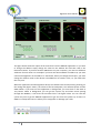
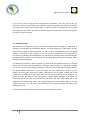
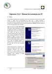
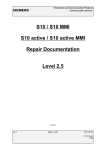
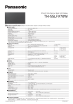
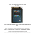
Digimeter Users Manual
Digimeter V1.0 – User’s Manual
1 – On the computer
The Medidor application gives you the data send by the Digimeter system. It shows the
forward power, the reflected power and the SWR relation. This application has an interesting
function: it can make a log file with this information for future analysis. You can choose the
interval time between the data writing on the file. You can use this functionality to analyze
your system when you work with it in a transparent manner. When you stop working normally,
then, you can open the log file and analyze your system power performance.
When the application starts, it will try to communicate with the Digimeter device. If the
application does not find the Digimeter device, it will send you a message like the one in the
figure bellow.
This error message indicates that the Digimeter is not connected to your computer. It also can
mean that the device address is no correct. If you have other ARR devices connected, if
necessary, you must change the devices addresses. There cannot be two devices using the
same address.
1
CT2KAV – [email protected]
Digimeter Users Manual
The figure above shows the aspect of the main form from the Medidor application. If you want
to change the address simply change the value on the Address box and then click in the
Reconnect button. If you have another ARR device on your computer, you must use different
addresses for each other. For example if you have one AntennaSwitch on address 0, you must
connect the Digimeter on the address 1. Sometimes, when you change the usb port, you must
change the address value on the devices. The addresses are saved in a file, so, you need to do
this only once.
When the application find the Digimeter device, the software will start functioning showing, on
the analog and digital meters, the values of the forward power, the reflected power and the
SWR relation. If you want use this application in background, you must click on the Send to
Tray button. When in background, you can get the system tray and when mouse passing
through the Medidor, it will show the measures like in the figure below. You can click the
system tray icon to get the Medidor application to get out from the system tray. If there is a
SWR>=3:1 a beep will come to advise you to stop power or damage your radio.
2
CT2KAV – [email protected]
Digimeter Users Manual
If you want to make a log file with the Digimeter information, you must click on the Log
checkbox. You must choose the file for saving the log on the windows that appears. By default,
the system will not log when forward power is 0, but if you want to change that you can check
the Log with no Power box. The Interval value dictates the time between entries in the log file.
This time is given in seconds.
2 – The digital module
This module of the Digimeter system must be connected to the HF bridge by a DB9 cable as
showed in the Assembly and Calibration Manual. You must power the module with 13.8V Dc.
After that connection is made and power on state is ready, and independently of the digital
module is connected to the computer or not, the power and SWR values are showed in the
LCD display. Pf indicates de forward power, Pr indicates the reflected power and SWR indicates
the SWR relation. If SWR>3:1, the buzzer will ring and the SWR Led indicator will bright. When
Pf>0 the PPT led will light on.
To calibrate this module, it will be necessary to push down the calibration button. In the LCD
display the instructions for this operation are showed steep by steep. To calibrate this module
you first must make the HF bridge calibration, otherwise you can damage the digital module.
The digital module calibration is just a tiny adjust, the main calibration is made on the HF
bridge. You must apply, with the RF cables connected to the HF bridge a 100W CW or FM
modulation on 14MHz band. You must adjust the VF potentiometer R7 to get 100W on the
display with the RF cables on the right position (Direct cables message). Push down the
calibration button and then you must reverse the cables and then apply 100W CW or FM
modulation on 14Mhz band. Adjust the VR potentiometer R6 to get 100W value on the LCD
display. After that, you push down the calibration button and the module will reboot. The
calibration is done.
This procedure is well explained in the Assembly and calibration manual.
3
CT2KAV – [email protected]