1
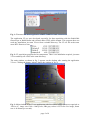
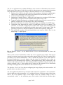
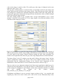
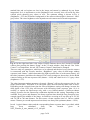
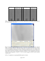
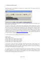
BAM VIII.35
Dr. Uwe Zscherpel
Dr. O. Alekseychuk
http://www.kb.bam.de/~alex/v2
July 22nd 2009
Manual for installation of software, image acquisition via Firewire and detector
calibration
This manual provides details to operate the Radio5000 Fluoroscope.
1. Software and hardware installation
The selected Firewire camera FOculus FO442SB requires special drivers to operate under
Windows operating systems. The manufacturer (NET GmbH in Germany) provides on its web
site the latest version (http://www.net-gmbh.com). The following files are available today for
download concerning the FO442SB camera:
1. FOcontrol_Install_4.0.3.0.exe
(the camera drivers and the demo application
FOcontrol.exe)
2. FOControl_V3.0.7.0_manual.pdf (the user manual for the demo application
FOcontrol.exe)
3. NET_FOculus_S_user_manual_v1.15_001.pdf (the detailed description of the
FO442SB camera specifications and the software and driver installation)
The first file has to be started once at the computer to install all necessary drivers and the
demo application “FOcontrol.exe”. Finally, there will be installed a link to this demo
application on the desktop. Please reconnect the camera after this software installation to the
hot pluggable Firewire interface. ONLY THEN all necessary windows drivers will be
installed too and the camera is visible under the system -> hardware -> device manager as
“image processing device” with the name “NET GmbH 1394 Digital Camera”. When the
device is shown in the manager window without a yellow exclamation mark, the camera is
ready for operation.
A sound beep should be heard from the computer, every time the camera is connected or
disconnected on the running windows system. The camera power has to be provided by the
Firewire cable. A standard 6 pin IEEE 1394 cable and connector at the computer provide this
power, the smaller 4 pin connectors found on laptops does not. Here adapter cables from 4
pin to 6 pin with an additionally power supply of 12 V should be used.
DANGER! Please connect the 6 pin cable only side correctly! With brutal force the steel
frame of the 6 pin connector can be expanded to such a size, that the cable can be plugged in
turned by 180°. If than the power is provided to the camera, the exit circuit of the Firewire
interface inside the camera is definitely destroyed and the camera has to be sent for repair to
the manufacturer Net GmbH! Be carefully!
2. Software operation and image acquisition
As next step start from the FOcontrol application the desktop link. Select the set-ups as shown
in fig.1. Clicking the button “start camera” will show a live camera image, “stop camera” will
erase this image from the window. If all works fine, please stop the camera and exit
FOControl. For more information, see the manual FOControl_V3.0.7.0_manual.pdf.
page 1 of 8
Fig. 1: FOcontrol.exe demo application of NET GmbH for basic camera tests
The application V2.exe was developed especially for data acquisition with the Radio5000
fluoroscope at BAM Berlin and released under GNU public domain. This program does not
need any installation, just start V2.exe from a suitable directory. The V2.exe file needs some
more DLL libraries to run:
Fig. 2: V2 acquisition program and its components. There is no installation required, just start
V2.exe and keep all 4 files in the same directory.
The main window as shown in fig. 3 appears on the desktop after starting the application
V2.exe. Clicking the button “About” shows the window of fig. 4:
Fig. 3: Main window of the V2.exe application with live camera image (camera recognized as
“Device 0”, image size 1388 x 1040 pixels, 8Bit gray values 0-255 in the live image, frame
rate: 6.49 frames per second).
page 2 of 8
The V2.exe application uses standard Windows video streams via DirectShow and ActiveX.
In this way a wide range of video devices with live data streams are supported, at the moment
only with 8 Bit color or gray scale images. The basic functions of V2 are as following:
1. Display of live video in the main window with markers on information clipping (gray
values of 0 are displayed in blue color, gray values of 255 in red color, see fig. 3).
2. Control of camera settings via “Setup” button.
3. Integration of multiple fames to 16-Bit gray scale images by averaging of 8 Bit frames
and scaling to 16 bits for increased dynamic and signal-to-noise ratio.
4. Temporal median filtering prior averaging for suppression of directly converted X-ray
photons, reaching the CCD chip despite all of the lead shielding.
5. Selection of file name for storage of integrated images as standard 16 bit TIFF image.
6. Calibration of the integrated raw images via calibration set-up file (see chapter 3) for
reduction of electronic background (so-called dark image) and in-homogeneities
between single pixels via additionally multiple gain images (“bright images” with flat
field X-ray exposure of different intensities). It allows also replacing “bad pixels”.
7. The calibration procedure, file and functionality is the same as used in ISee! via the
menu Image -> Adjust pixels …
Fig. 4: Window “About” for the BAM software V2.exe with information on license and
availability.
There can be several circumstances, where the V2.exe program just crashes. This can be
coursed by software bugs between the used public domain library for Video-I/O and the DLLs
provided by the camera manufacturer. This is outside the program V2.exe and cannot be
prevented completely. It can also happen, that the camera is recognized, but no data are
transferred (0 fps and black image window). This happens mostly after reconnection of the
camera to the system. In this case, start the FOcontrol.exe application and start and stop the
camera as shown in fig. 1. After exiting the FOControl.exe, the program V2.exe should start
smoothly and display the correct camera live data as shown in fig. 3.
The first line “View” in V2.exe allows configuring the image display in the main window. All
possible choices are shown in fig. 5.
The most right menu shown in fig. 5 bottom needs some more explanation. “View automatic”
is the default gray scale presentation, i.e. by scaling of the max.16 bit gray values in the image
data to the 8 bit dynamic range of the display. Here the complete image (View) is
automatically scaled, i.e. the minimum gray value scaled to black and the maximum gray
page 3 of 8
value in the image is scaled to white. The scaled gray value range is displayed on the most
right side of the “View:” line.
The top option “ROI automatic” is selected, when a red rectangle is drawn by the mouse (left
mouse button pressed) inside the main image window. Than only the gray values inside this
red rectangle are considered for automatic histogram scaling to full 8 bit of the display. By
pressing the right mouse button and moving the mouse the position of this red ROI rectangle
can be moved inside image window.
The other settings shown in fig. 5 bottom from “16 bpp (full dynamic)” up to “4 bits
dynamic” fixed the Look-up table (LUT) for image display to the indicated number of bits
considered in the image gray values.
Fig. 5: All possibilities to control the image display in the V2 main window, top: selection of
different data streams, middle: image display with different zooming factors, also adjustable
via scroll wheel on the mouse, bottom: different settings for gray value stretching. The
numbers on the right hand side show the gray value range displayed between black and white.
The button “Reset” in the V2 window resets the used IO library, the button “Setup” calls the
camera configuration window. The layout of the set-up window depends on the camera
functionality and the implemented features of the ActiveX video components by the
manufacturer of the camera driver. For the FOculus camera this is shown in fig. 6.
There are only two very important settings for the fluoroscopic application, which have to be
adjusted correctly and checked, every time the camera is connected again via Firewire. These
are the settings for “Brightness” and “Shutter”, all the other parameters should be as default
and
not
changed.
For
details
see
the
camera
manual
NET_FOculus_S_user_manual_v1.15_001.pdf.
If Brightness and Shutter is not set correctly, images as shown in fig. 3 are acquired with
clipped gray values (Zero value in blue, max. value of 255 in red). Information kept in the
page 4 of 8
marked blue and red regions are lost in the image and cannot by enhanced by any frame
integration! So it is important to set the Brightness level correctly, this will avoid any blue
colored pixels showing gray values of zero. The optimum setting is shown in Fig. 6
(Brightness = 555) the electronic background of the camera without light is between 1 and 2
gray values. The exact brightness value depends on each camera and its actual temperature.
Fig. 6: On the right hand side is the camera control windows shown for FOculus FO 442SB
camera after pressing the button “Setup” in the V2 main window. Only the tab “Net Video
Control” is of importance, the tab “NET camera Control” should not be changed.
There are only two parameters, which have to be adjusted and checked every time the camera
is reconnected with the Firewire interface, “Brightness” (gray value of dark image without
exposure) and “Stutter” (which determines the light exposure time of each camera frame). All
the other parameters should not be changed. The correct settings are shown here for the BAM
camera working at 200 ms exposure time (shutter = 1829) and a dark level of 1-2 gray values
(brightness = 555).
The other important setting parameter electronic “Shutter” will set the exposure time for the
single camera frame. This value is an encrypted value derived from the frame time in msec.
Depending on the selected frame time the correct Brightness setting will change, because the
dark signal of the CCD chip will increase with increasing frame exposure time. So it is
usefully, to operate the fluoroscope only with a very limited number of different shutter
settings, because also the fluoroscope calibration depends on this setting. Depending on the
available X-ray power and distances, the frame exposure time should be long enough to have
enough signal in the middle of the image. At BAM we are using an X-ray tube up to 225 kV
and 1.8 kW at 700 mm distance. For this source a frame exposure time of 200 ms (which
means 5 frames per second unprocessed raw data) was always the optimum (shutter = 1829).
In tab. 1 typical shutter values and the corresponding frame exposure time is provided, which
have
been
calculated
from
the
formula
given
in
NET_FOculus_S_user_manual_v1.15_001.pdf.
page 5 of 8
1394 Shutter
Frame
1394 Shutter
Frame
exposure time
exposure time
value
s
value
s
1
1 µs
1729
0.1
10
10 µs
1829
0.2
100
100 µs
2129
0.5
500
500 µs
2422
1
550
1 ms
2522
2
650
2 ms
2822
5
950
5 ms
2944
10
1045
10 ms
3044
20
1145
20 ms
3318
60
1445
50 ms
3323
65
Tab. 1: Frame exposure time of the CCD chip in dependence of the shutter value setting in
the camera software control tab.
Fig, 7: Example of ongoing integration with V2 (9 frames of 50 are already done) using all
features including calibration. The acquired gray values of a single frame are between 14 and
129, so no clipping is shown and the source calibration should work also. The computer load
by the applied temporal filtering of 5 frames and image integration decreases the frame rate
from 5 fps to 2 fps. So an overall exposure time of 50x0.2s = 10s is integrated, but the time
needed for this integration is 50x0.5s = 25s! So a faster computer will save some overhead
exposure time.
In Fig. 7 a snapshot on an ongoing flatfield exposure is shown.
page 6 of 8
3. Calibration of fluoroscope
As shown in fig. 7, the calibration is controlled via a simple text file. The content of the used
file here is as following:
Fig. 7: Principle of fluoroscope calibration via text file containing keywords and image names
used for gray value correction.
The keyword “adjust_black” control that the first image (dark_200ms_50frames.tif”) is used
to subtract any dark offset from each of the following white images. All the following images
(here only one image “bright_200ms_50frames.tif” with a homogeneous exposure at the
sceen is used) are used for pixel wise linear interpolation of the image to be calibrated for
equalization of the individual pixel responses to provide the same median gray value of the
calibration image. For more details on image calibration see for documentation included
within the ISee! package (see http://www.kb.bam.de/~alex/ic). There identical functions can
be used via Image -> Adjust pixels.
A typical calibration text file for the BAM fluoroscope is given here:
$adjust_black
Dark2-200ms-240s.tif
Fe5mm-220kV-1mA-700mm-200ms-180s.tif
Fe5mm-220kV-2mA-700mm-200ms-120s.tif
Fe5mm-220kV-4mA-700mm-200ms-120s.tif
Fe5mm-220kV-8mA-700mm-200ms-60s.tif
A steel plate of 5mm was used for calibration. Beside the dark image 4 white images were
generated for calibration of the full dynamic range. With 8 mA at 700 mm distance no
detector saturation was obtained. The other, darker images should have gray values linearly
increasing from the darkest to the brightest image.
It is usefully to have at least the double integration time for detector calibration as used later
for image acquisition. If the source to detector distance will change, some artifacts in the
detector calibration will show, because of the changes X-ray source shading overlaying the
internal detector shading (mainly from objective).
page 7 of 8
In Fig. 8 the improvement of image quality is shown before and after calibration. Of course,
during acquisition of images for fluoroscope calibration, the calibration function in V2 has to
be deactivated (e.g. no source calibration text file as in fig. 4)!
Fig. 8: Images of an Inconel step wedge with ASTM 2-2T penetrameters (after digital high
pass filtering “Enhance details”). Top: image without calibration, only 2-4T hole are visible,
Bottom: after application of fluoroscope calibration to the raw data. Vertical banding is
removed, the steps are more homogeneous and 2-2T holes are visible between 0.2 and 0.5
inch thickness. Exposure conditions are given in the displayed file name.
page 8 of 8