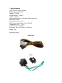
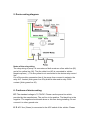
1
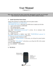
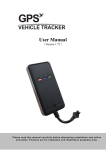
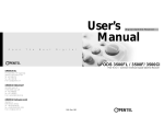
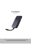
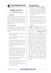
GPS Vehicle Tracker
(GPS+GSM+GPRS)
(LY-H809+)
User Manual
Please read this manual carefully before attempting installation and online
activation. Pictures are for indication and illustration purposes only.
1. Specification
GSM: 850/900/1800/1900MHz
GPRS: Class 12, TCP/ IP
Voltage: 7-75VDC
Current:≈22mA(12vDC)
≈12mA(24vDC)
GPS positioning time: Cold start -38sec(open sky)
Warm start -32sec
Hot start 2sec (open sky)
GPS positioning precision: 10m (2D RM)
Temperature: -20℃ ~ +70℃
Humidity: 20% ~ 80% RH
Dimension: 90.0(L)x45.0(W) x13.5(H)mm
Weight: 45g
2.Accessories
power line
Relay
3. Status indicator
3.1 Red LED (power/working status)
LED Status
Meaning
Exterual power supply to provide
Shine 1s, dark 2s
power for the device
Internal battery to provide power for
Shine 0.1s, dark 2s
the device
Continuously in dark state
Power off / internal fault
3.2 Blue LED(GPS status)
LED Status
Meaning
Shine 1s, dark 2s
Searching GPS signal
Shine 0.1s, dark 2s
GPS located
Continuously in dark state
GPS not located
3.3 Yellow LED(GSM status indicator)
LED Status
Meaning
Shine 1s, dark 2s
GSM initialization
Shine 0.1s, dark 2s
GSM conversation/Start GPRS
Continuously in dark state
No GSM signal
4. H809+ interface introduction
5. Device wiring diagram:
Notes of the relay wiring
The relay wiring of pump: oil connectors of both ends are a fine white line (85)
and a fine yellow line (86). The fine white line (85) is connected to vehicle
Negative power (-). The fine yellow line is connected to the device relay control
line.
Cut off the positive connection line of the pump; then connect in series to the
relay N.C. contact (thick green line 87a) and the other end to relay COM
contact ((thick green line 30).
6. Cautions of device wiring
6.1 The standard voltage is 7V-75VDC. Please use the power line which
provided by the manufacturer. The red line is the positive. The black line is the
negative. The negative should earth alone or link iron during installing. Do not
connect it to other ground wire.
6. 2 ACC line (Green) is connected to the ACC switch of the vehicle. Please
make sure to connect the ACC line. The tracker will decide whether to enter
ignition detection according to ACC status. If do not connect to ACC line, the
device will enter ignition detection status. If the vehicle vibrates when moving,
it will activate the vibration alarm. If there is no need for the theftproof function,
connect the ACC line to the positive in parallel and keep high level.
6.3 Tele-cutoff (petrol/ electricity) control line (yellow) is connected to pin 86 of
the Tele-cutoff (petrol/ electricity) relay (equal to the yellow line of the relay
socket).
7. Function setting
7.1 Location search methods: GPRS background/ SMS
7.2 The based service platform:
7.3 Set the service center number:
If you want to use SMS to set terminal’s working parameter, you must set the
service center number of the SIM card first. Terminal only accept SMS
instructions of the service center number, you can set your mobile phone
number as the service center number. In order to ensure the safety of
users,you must use the password to set service center number. The initial
password is “123456”. Password can be modified.
Service center number set instruction:
pw,123456,center,00000000000#
Example: pw,123456,center,13800138000#
If the service center number is set successful, the terminal will reply: Master
command set successfully!
If the password is incorrect, the terminal will reply: "password mistake!"
Note: you can only set one service center number.
7.4 Delete the service center number
Instruction: pw,123456,center,d#
If the instruction is set successful, the terminal will no reply message.
7.5 Modification of password
Instruction: pw: new password (6 digits)#
Example: pw, 888888#
If the password is modified successful, the terminal will reply: "password
success! Password for 888888".
If the setting is incorrect, then reply "password format error!"
The default password is “123456”.
7.6 Inquire the parameter setting
Instruction: check#
Reply Message: SN:1234567890,interval,upload:15,sleep:10,
SN:1234567890-- Serial Number
upload—GPRS Data upload interval.
sleep—working time before enter sleep if the
7.7 Modify the upload interval time of GPRS data
The upload interval time of GPRS data can be set to between 10s and
18000s.The default setting is 15s.
Instruction: upload, Timing time (in seconds) #
Example: upload,15#
7.8 Working time before enter sleep setting
The default working time before enter sleep is 10 minutes, set range: 1-1800
minutes
Instruction: sleep, Timing time (in minutes) #
Example: sleep,10#
7.9 Language and time zone setting
The terminal provide the Chinese and the English language, the different areas
of time according to the time zone setting.
Instruction: lang,x,zone,n#
Language options X: 0 is English, 1 is Chinese,
Time zone n: East eight area for 8, west three areas for -3, the default
language 0, time zone -3.
7.10 Set configuration of H809+
7.10.1 APN setting
Indosatgprs is the APN of the Indonesian operator Indosat, please replace it by
the local one. You might need to give a call to the local operator to ask them
what their APN is.
If the APN needs login password
The SMS is as following:
apn,<apn>,user,<user>,pd,<password>,plmn,<pimn>#
e.g.: apn,cmnet#
Reply information for successful setting: OK
7.10.2 IP setting
After the success of APN settings, to send the following message setting
device to a IP address:
ip, <ip>,port, <port>#
e.g.: ip,211.154.154.230,port,6969#
(If you use the manufacturer's server, sending the information)
7.11 Operation of device
7.11.1 Oil cut-off
When a vehicle is in an emergency, to the terminal SIM card send command to
cut off the oil and electricity.
Short message instruction format: relay,1#
7.11.2 Restoring Oil
When the vehicle is dangerous to lift, to terminal SIM card send command to
restore oil electricity.
Short message instruction format: relay,0#
7.12 Restart terminal
Instruction: reset#
When the terminal received the instrution, it will be restart terminal after 1 min.
8、Terminal user's manual
8.1 Location check
8.1.1 Address check by SMS
Instruction: where#
If GPS fixed success, the terminal replies Address.
If GPS fixed failure, the terminal replies: "unable to get the correct GPS data,
please try again!"
8.1.2 Location check by Google map
Instruction: url#
If GPS fixed success, the terminal reply: Google map link
If GPS fixed failure, the terminal replies: "unable to get the correct GPS data,
please try again!"
If your mobile phone can connect to the Internet, you can open the Google
map link to check the position of the terminal; also can check the position by
the browser of computer for input the Google map link.
9. Method of installation
9.1 Preparation before installation
1) Open the packing box to check whether the type of device is correct and
whether the accessories are included.
2) This product is a high-tech electronic device, installation should be
undertaken by a professional.
3) Please follow the following procedures to install your H809+. During
installation, there should be no power to the device.
9.2 Installing SIM card: each H809+ needs to insert a GSM SIM card.The
SIM card used should be enabled for GPRS.
1) Testing SIM card: to test SIM card, please install it into a normal GSM
mobile and ensure it can send and receive SMS, and enables for GPRS.If
there is an access password, or pin, please cancel it; Testing GPRS network
connection
2) Installing SIM card: Remove the upper cover of device, insert SIM card as
shown then replace cover, lock the shell with 3 bolts.
9.3 Selecting installation place and fixing it. There are two kinds of
installation: covert and non covert. If you need the covert installation, please
refer installation to an auto electrical contractor.
NOTE:
1) To prevent theft of the H809+, the device should be installed as covertly as
possible.
2) Avoid placing the H809+ close to higher power electrical devices, such as
reversing radar anti-theft device or other vehicle communication equipment;
3) The H809+ should be fixed into position with cable ties or wide double-side
tape.
4) Your H809+ has built-in GSM antenna and GPS antenna. During
installation, please make sure the receiving side face is up, with no metal
object above the device to interfere with GPS reception. The following places
are suggested for nstallation:
- under the dash board below the front windshield;
- in the parcel shelf in the rear;
- in the front bumper( non-material face), please ensure the device cannot get
wet;
- Under the wiper version (non-metal), please ensure the device cannot get
wet;
Notice:
if the windshield is pasted with metal thermal-protective coating, it may affect
the performance of the device. In this case, please change the installation
place after consulting the professional.
5) Non Covert Installation,
Firstly fix the H809+ on the dash board below windshield.
10. Cautions of device wiring
10.1 The standard voltage is 7V-75V, the red wire is the positive, the black wire
is the negative.
10.2 Please connect the black wire to ground.
10.3 After connecting the power cord, run the power cord plug to the device.
After installation, supply power to device.
10.4 Covert installation: car battery cord is standard, with 1A FUSE for
short-circuit over current protection.
10.5 Non covert installation: cigar lighter cord is optional, with 2A FUSE for
short-circuit over current protection. Please contact your dealer if this mode is
needed.
11. Power on/off
11.1 The H809+ will power on automatically when connected to power. During
normal operation, red power LED flashes, while blue GPS LED and green
GSM LED keep Bright1 seconds dark2 seconds. During signal searching
process, GPS or GSM LED will flash. If there is no light presenting on LEDs,
the device is not working normally.
11.2 The device will power off after power is disconnected.
11.3 Side key function
At normal-work indication status, press the side key, all the three LEDs will
extinguish and then the H809+ will enter covert working mode. Press the key
again, the three LEDs will go back to normal-work indication status.
12. GPS troubleshooting
12.1 If GPS can not receive the signals normally, please drive to the open
areas for positioning. Generally, it needs 1-2 minutes to receive the first
coordinates. If the data can not be received after 2-3 minutes, please check
the installation position of the device, making sure it is not being shielded by
any metal.
12.2 If GSM can not receive the signals normally, please check whether SIM
card is installed correctly or there is no GSM signal at the location you are,
such as a basement parking, please drive to a place covered by GSM signal
reception.
12.3 If the red LED does not work when power is connected, please
check whether the fuse is blown. If so, please replace the fuse.
12.4 If the three LEDs do not turn on when power up, press the down side key,
if the three LEDs recover normally, the device is working normally.
12.5 If you have enabled the web based tracking application, and the H809+
displays off-line on the platform, please check 3 LEDs status indicators first.
You can check the status of the SIM card when you are in an inconvenient
situation. Please refer to the following steps:
1). Call the SIM card number of the device to check whether you can get
through.
2). Check whether the SIM card supports GPRS and a local APN.
3). Check the GSM/GPS reception area.
4). Check whether your SIM card charge is overdue.
5). Check if the connector and device is loose or the fuse has blown out.
12. Web Based Tracking Online activation
The GPRS web based tracking platform allows real time tracking with the
latest Google maps. There is also a playback feature that allows you to view
where the vehicle has been for up to 30 days in the past making it ideal for fleet
management