1
I
United States Patent [191
[111
4,205,300
Haley et a1.
[45]
May 27, 1980
[54]
[75]
PROGRAMMABLE ALARM SYSTEM FOR
3,932,855
1/1976
Hamilton ........................... .. 340/685
MARINE LOADING ARMS
3,944,798
3/1976
Eaton ...... ..
364/559
4,084,247
4/1978
Ball ........................... ..
364/559
Inventors: Frank P. Haley, Upland; Louis S.
_
McTamaney, San Jose’ both of Calm
'
_
_
Primary Exammer—-John W. Caldwell, ‘Sr.
_
Assistant Examiner-Joseph E. Nowicki
{73] Ass‘gne‘e: FMC cmpomnon’ San Jose’ Calif‘
[21] Appl‘ No‘; 853,300
Attorney, Agent, or Firm-Lloyd B. Guernsey; W.
William Ritt, Jr.; John F. Verhoeven
[22] Filed:
[57]
Nov. 21, 1977
[51]
1112.013 ...................... .. G08B 21/00; B65B 1/04;
601C 1/00; (301B 3/56
[52] US. Cl. ................................... .. 340/686; 33/1 M;
ABSTRACT
A system for sensing the posimn in space of the Outer
end of an articulated ?uid loading arm while it is con
nected to a marine tanker or other transport vessel, and
137/556; 141/387; 364/559
for sounding an alarm if the arm’s operating envelope is
[58] Field of Search ............. .. 340/679, 685, 686, 689;
exceeded. The sensing system includes means for deter
364/110, 559; 137/554, 556, 615; 212/39 A, 39
mining various angles representative of the orientation
MS; 222/41, 42; 141/94, 337; 285/93; 33/ 1 M
of the booms or limbs of the arm, and a microprocessor
[56]
References Cited
for using these angles to compute the spatial position of
us‘ PATENT DOCUMENTS
safe and unsafe areas of operation of the arm are stored
the arm’s outboard end. The boundaries between the
1,931,107
10/1933
Dowell et al. ..
13;
,
...... .. 114/230
----------- --
,
v0
-
a
2,898,954 3/1959 Freeman
2,927,607
3,050,092
3,073,280
3,566,386
3/1960
8/1962
1/1963
Bily ............... ..
Palcanis et a1. _
This} ......... __
2/ 1971
Hamilton
3,854,128
12/ E974
Yamagishi .,
12/1975
Sarrell .............................. .. 33/125 R
9/1974
.
.
3'’
_
-
212/39 R
Hamilton
PROM
1"” ' Y C, ‘img
Y Smm‘g ‘‘ “8}” set ° mm ,“Y "a “S
1n the digital memory. If desired, the locat1on of the
boundaries can be made to depend upon the velocity of
the arm as it is being maneuvered. When the outboard
end of the arm moves into an unsafe area an alarm
3,922,789
3,833,932
om et
aregilca'lllbe $31’) desmi'd Shape’ and F}: shgpe ca‘; be
137/615
141/387
116/124
340/267
3,833,130 9/1974
1
-
141/86
lsfncheza-l-m
Gerdes
at al.
1
in a digital memory and compared with the actual posi
tion of the arm. The boundaries which de?ne the safe
predetermm
distance art er mto t e unsa e area.
.... .. 340/267 C
TIMER
19 Claims, 16 Drawing Figures
'45
l
cwcx GEN
A1
PROCESSOR ~41
'I
4a
1
MEMORY
~——————-—\
L
L
/P'
I10
I
EXPANDER
1
singing"; .t
'
1
HORN
ANGLE
SENSOR“ N
/P2
I
I
PM 1
MULTIPLEX
5mm"
A
cows/315R
1
/ 4s
\ 5o
SUPPLY
VOLTAGE
p38
STATUS
SWITCHES
gb'vlih
°""
1-1
“49
‘40
ANGLE
5121150119 2
.
Smmds’ a“?! 3;‘: System ‘i Shh“ df’w“ ‘lithe a"? MW“ 3
340/267 c
J
US, Patent ‘ May 27, 1980
Sheet 1 of 12
IE'Il3_
U.S. Patent
May 27, 1980
Sheet 2 of 12
4,295,308
FIE _
US. Patent
May 27, 1980
Sheet 3 of 12
4,2053%8
U.S. Patant
May 21, 1980
mowun.
Sheet 4 of 12
vm
m
0
6‘1ml234
10/9
0612.1549.23
B
B
MD
‘234561
Mo65432
\\2
4,205,308
US. Patent
May 27, 1980
Sheet 6 of 12
4,205,38
iF'IGJ;
X Z PLANE
XY PLANE
SECONNSF-
—
-
-
_
_._
'6
.
SECONDARY BOUNDARY (m FEET)
é
US. Patent
May 27, 1980
Sheet 7 of 12
MEMORY ADDRESS
‘
1920
2993
FUNCT?ON
w
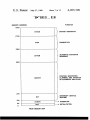
SYSCN
1720
> SYSTEM cowsmms
-<
DIAG
I320
> DIAGNOSTICS
#
4
AUTOMATIC sau'roowm
SHTDN
I020
> SEQUENCE
-<
POSITION MONITORING
MONTR
} ALARMING, AND INETIATION
OF AUTOMATIC SHUTDOWN
270
m1.
INTERRUPT SERVICE
ROUTINE
I20
SCHDR
50
o
!NIT
PROM MEMORY MAP
-—-> SCHEDULER
-—-> INITIALIZATION
US. Patent
May 27, 1980
Sheet 8 of 12
4,205,308
( PWRON )
IN iTiALI ZE
SYSTEM
READ, DEBOUNCE AND
UPDATE EVENT/
PANEL SWITCHES
SET SYSTEM T0
'ALARM MODE
SHUTDOWN
ACTéVE
RESET ALARM
MODE
CLEAR ALARM
LIGHT AND
ALARM HORN
1 SEC.
SINCE LAST
ANGLE
UPDATE
'7
F'IE __ 1E]
US. Patent
May 27, 1980
Sheet‘9 of 12
4,2093
FIB __ l].
SHUTDOWN
m PROGRESS
'
‘(55
?
.| SEC.
SINCE LAST
SHUTDOWN
YES
UPQPATE
UPDATE SHUT
DOWN OPERATION ‘
.01 SEC.
SINCE LAST
SWITCH
UPDATE
?
YES
U.S. Patent
May 27, 1980
4,205,308
Sheet 10 0f 12
F'IE _ 12
READ ANGLE SENSOR
SUPPLY VOLTAGE
WITHIN
ADJUSTMENT
LIMITS
YES
?
TURN OFF "OUT OF
ADJUSTM ENT" LED
TURN ON "OUT OF
ADJUSTMENT" LED
READ ANGLE SENSOR,
APPLY SUPPLY VOLTAGE
CORRECTION, AND
COMPUTE ANGLE
NO
ANOTHER
SEN?SOR
CALCULATE
ARM POSITION
YES
ARM WITHIN
SPECIFIED
VOLUME
?
US Patent
May 27, 1980
Sheet 11 of 12
4,2053
_ 1:3
SOUND ALARM
HORN
UPDATE ARM
COORDINATES AND
CALCULATE VEL.
SHUTDOWN
MODE
g;
?
SHUTDOWN
m PROGRESS
?
'
GET VELOCITY DEPENDENT
SHUTDOWN LIMITS
SET SYSTEM TO
SHUTDOWN STATE
i2B;
US. Patent
May 27, 1980
Sheet 12 of 12
4,205,308
1%
T'IG_1CL
4,205,308
I
PROGRAMMABLE ALARM SYSTEM FOR
MARINE LOADING ARMS
2
factory, for they in effect de?ne a space within which
the arm can operate that is bounded either by arcuate
surfaces or by planes passing through the vertical pivot
axis of the arm on the riser. Thus, if a speci?ed rectan-
BACKGROUND OF THE INVENTION
5. gular operating envelope is to be accommodated, fairly
extensive areas outside this envelope will also be within
1. Field of the Invention
the operating range of the arm, and the stresses which
This invention relates to articulated ?uid transferring
apparatus, and more particularly to marine loading arms
occur when the end of the arm is in these outside areas
and vertical axes, and an outboard boom or limb con
connected booms or limbs one of which is pivotally
nected by a pipe swivel joint to the inboard limb so as to
be pivotal relative thereto about a horizontal axis. The
outer end of the outboard limb is adapted to be con
nected to a pipe manifold on a tanker located within the
reach of the arm, such as by a remotely-controllable
mounted on a vertical riser or other ?xed support. The
coupler device.
angle representative of the vertical orientation of the
and alarm systems for determining the spatial position 1.0 can substantially exceed those occurring within the
envelope. It is therefore important that a system be
of the outer end of such arms with respect to the arm
provided for monitoring the actual position of the out
booms or limbs.
board end of the arm and for sounding an alarm when
2. Description of the Prior Art
ever the end of the arm extends outside the speci?ed
Fluid loading arms constructed of articulated pipe are
envelope.
extensively used in the petroleum industry for transfer
ring oil or other ?uids between a jetty, wharf, or other
SUMMARYv OF THE INVENTION
loading station and a marine tanker moored alongside.
The present invention comprises a system for sensing
Such an arm generally comprises an inboard boom or
limb supported on a vertical riser pipe by pipe swivel
the position in space of the end of an articulated ?uid
joints to facilitate pivotal movement about‘ horizontal
loading arm, the arm comprising a plurality of pivotally
When an installation of this type is being designed,
minimum requirements are set for the reach of the arm.
These requirements are expressed in terms of the maxi
mum horizontal displacement of the tanker parallel to
and away from the jetty relative to a datum position, the
maximum displacement away from the jetty due to
variations in the distance between the tanker manifold
and the tanker rail, and the maximum vertical displace
ment due to variations in the water level and the height
of the tanker manifold relative to the water level. These
displacements de?ne a three-dimensional space that is
rectangular in section when viewed in plan or in eleva
tion, either parallel to or perpendicular to the jetty, and
this space is known as the arm’s “operating envelope”.
The arm must be able to accommodate all of these dis
placements so that a safe and secure connection to the
.tanker’s manifold can be established and maintained
within the limits of this envelope.
Most articulated arms are counterbalanced so that 45
when empty they are substantially self-supporting.
However, the weight of the oil or other ?uid in the arm
during use is not counterbalanced, and thus must be
supported in part by the tanker manifold to which the
system includes means for sensing a ?rst angle represen
tative of the vertical orientation of one limb of the arm,
means for sensing a second angle representative of the
horizontal slew of the arm, means for sensing a third
other limb or limbs, and means for deriving from the
sensed angles an indication of the spatial position of the
end of the arm.
The system further includes means for storing the
spatial boundaries of a safe working area for the end of
the loading arm, means for comparing the actual posi
tion in space of the arm with the safe boundaries and
means for generating an alarm signal when the end of
the arm reaches beyond any of the safe boundaries.
When the arm continues to move beyond this ?rst set of
safe boundaries to a second set of boundaries, the sys
tem generates a shut-down signal which disables the
loading arm.
BRIEF DESCRIPTION OF THE DRAWINGS
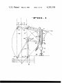
FIG. 1 is a schematic side elevation of an articulated
?uid loading arm mounted on a jetty or wharf accord
ing to the present invention, illustrating in phantom the
arm in several operating positions, and also showing the
arm’s operating envelope as viewed from the side.
FIG. 2 is a schematic plan view of the arm and oper
ating envelope of FIG. 1.
arm is connected. Clearly, the stress on the manifold 50
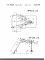
FIG. 3 is a schematic side elevation of the arm of
increases with the extension of the arm. In addition, the
FIGS. 1 and 2 illustrating the arm’s geometry from
manifold always faces towards the tanker rail, and the
which the location of the arm’s outer end can be de
stress to which the manifold can be subjected in a direc
rived.
tion perpendicular to the rail, and hence to the jetty, is
FIG. 4 is a schematic plan view of the arm of FIG. 1,
55
greater than the stress to which it can be subjected
illustrating the arm’s geometry in a horizontal plane.
parallel to the rail. The stress parallel to the rail in
creases with an increase in the slew angle, that is the
angle between the vertical plane in which the arm re
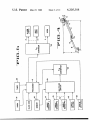
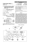
FIG. 5 is a basic block diagram representation of the
marine loading arm alarm circuitry.
.
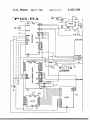
FIGS. 6A and 68 comprise a schematic diagram of a
sides and the vertical plane through the riser and normal
microcomputer
circuit which can be used to calculate
to the edge of the jetty. Thus, to prevent the stresses on 60 the various positions of the end of the loading arm and
the manifold from exceeding safe limits, the extension of
compare these positions with the safe boundaries which
the arm and the slew angle must be limited.
are stored in the microcomputer memory.
,
To achieve this limitation, alarm systems have been
FIG.
6C
is
a
schematic
diagram
of
an
electronic
de
provided for actuation in the event of the angle between
the inboard and outboard limbs exceeding a predeter 65 vice for sensing the attitude of the inboard and outboard
limbs.
mined limit, or in the event of the slew angle exceeding
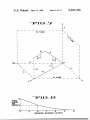
FIG. 7 is a diagrammatic representation of the arm of
a predetermined limit. These independent limits result
FIGS.
1 and 2, illustrating in three dimensional geome
in operating characteristics which are not entirely satis
3
4,205,308
try the location of the arm’s outer end in relation to the
various angles-which can be sensed.
FIG. 8 is a graph illustrating the relationship between
loading arm velocity and the position of the shut-down
boundaries.
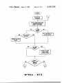
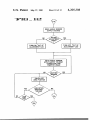
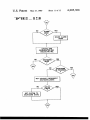
FIG. 9-13 illustrate flow charts which can be used in
understanding the operation of the microcomputer.
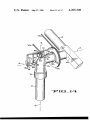
FIG. 14 is a perspective of a portion of a_ loading arm
equipped with another embodiment of the present in
vention, for sensing the attitude of the inboard and
outboard limbs of the arm.
DESCRIPTION OF THE PREFERRED
EMBODIMENT
Referring to FIGS. 1-4 of the drawings, an articu
lated arm according to the present invention is shown
comprising an inboard limb 10 pivotally connected
4
of movement between the planes 29 and 30 (FIG. 2) is
accounted for by allowable movements of the tanker
parallel to the jetty. To accommodate these movements
it must be possible for the connecting device 18 to reach
a manifold located anywhere within the three dimen
sional operating envelope de?ned by vertical planes 27,
28, 29 and 30 and horizontal planes 33 and 34.
The phantom representations of the arm in FIG. 1
show the orientation of the limbs 10 and 15 when the
arm is located in a vertical plane through the riser 14
and perpendicular to the edge of the jetty, and when the
connecting device 18 is in each of the four corners of
the rectangle de?ned by planes 27, 28, 33 and 34. It will
be appreciated that if an indication is to be given when
the connecting device 18 moves beyond the plane 28 for
example, it is necessary to monitor both angles g and d
(FIG. 3). If only one of these angles is monitored, it
about a horizontal axis at 12 to a riser or other ?xed
would not be possible to de?ne the plane 28 so as to
conduit 14. The articulated arm also comprises an out
determine when the connecting device 18 moves be
board limb 15 pivotally connected about another hori 20 yond this plane. As should be readily apparent, when
zontal axis 17 to the inboard limb, and a connecting
the arm is connected to a tanker manifold the stress on
device 18, such as a pipe ?ange or coupler, at the outer
the manifold increases as the connecting device 18
end of the limb 15 arranged for connecting the arm to a
moves away from the jetty 23.
tanker manifold. A sheave 19a is ?xed to the inboard
FIG. 2 shows the horizontal orientations of the limbs
end of the limb 15 and is mounted for pivotal movement 25 10 and 15 when the connecting device 18 is located at
about the horizontal axis 17 at the outboard end of the
each one of the intersections between the planes 27, 28,
limb 10. The sheave 19a is coupled by a pair of cables
29 and 30. If, for example, we consider the connecting
20a, 20b to another sheave 19b which is mounted for
device 18 when at the intersection of planes 28 and 30,
pivotal movement about the horizontal axis 12 at the
any increase in the slew angle f without a contraction of
upper end of the riser 14. The inboard sheave 19b can be
the arm would take the connecting device 18 beyond
rotated about the horizontal axis 12 by any of the means
the plane 30. Although the vertical components of
(not shown) commonly used for raising and lowering
stress on the tanker manifold beyond the plane 30 would
the outer end of the outboard limb 15. A counterweight
be no’ greater than if it were located at the intersection
22 connected to the inboard limb 10 neutralizes or
of planes 28 and 30, the lateral component of stress
greatly reduces the tendency of the loading arm to turn 35 parallel to the vertical face of the jetty 23 would be
about the horizontal axis 12 regardless of the position of
increased and therefore the total combination of stresses
the arm. The entire articulated arm assembly is mounted
would be unacceptable. Since the tanker manifold faces
on a jetty 23 provided with a ?exible fender 24.
toward the tanker rail, this lateral stress component
The mean sea level is represented in FIG. 1 by the
constitutes a shearing force and bending moment which
horizontal solid line 26, and the high and low water 40 can damage the manifold.
lines are represented by dash dot lines 26a, 26b respec
In order to provide the desired indication when a
tively, above and below the line 26. The installation is
connecting device 18 moves outside the three dimen
designed to accommodate a variety of tankers and
sional operating envelope de?ned by the planes 27, 28,
tanker movements during a loading operation. The
29, 30, 33 and 34, sensors are arranged to monitor the
arm’s operating envelope is de?ned as being limited by
angle (1 (FIGS. 3 and 7) to provide an indication of the
the vertical planes 27, 28, 29 and 30, and horizontal
vertical orientation of the limb 10 relative to the riser
planes 33, 34, as illustrated in FIGS. 1 and 2. However,
14, the angle g to provide an indication of the vertical
it should be understood that the microcomputer can be
orientation of the limb 15 relative to the riser 14, and to
used to de?ne an operating envelope having any desired
indicate the slew angle f (FIGS. 2 and 7). The sensors
shape, and the actual arm position can be compared 50 may comprise a variety of transducers; for example,
with such an operating envelope. All that is required is
potentiometers absolute shaft encoders, or other known
that the coordinates of the boundaries of such an operat
devices to provide analog outputs may be used to sense
ing envelope be stored in the memory of the microcom
the angles d, g and f. The angles (1 and g may also be
puter and the actual arm position compared therewith.
obtained by pendulum potentiometers P1 and P2 which
Curved envelopes can be closely approximated by a
are mounted on the respective limbs 10 and 15 (FIG. 3).
series of short, straight lines.
One such pendulum potentiometer which may be used
As indicated in FIGS. 1 and 2, the freedom of move
is the Model CPl7-0601-1 manufactured by Humphrey,
ment between the planes 27 and 28 in the horizontal
Inc., San Diego, Calif.
‘
direction away from the jetty 23 is accounted for by the
Since the sheaves 19a and 19b are positioned in a
portion L1 which represents the variation in distance 60 ?xed relation to the attitude of the outboard limb 15, the
between the manifold and rail of various tankers, and a
outboard potentiometer P2 may be mounted on the
portion L2 which represents the allowable movement
sheave 19b at the position P2’ (FIG. 3) where it will
of a tanker towards or away from the jetty.
provide elevation angle readings identical to the read
The freedom of movement between planes 33 and 34
in the vertical direction (FIG. 1) is accounted for by
variations in sea level, variations in the height of the
tankers, and variations in the height of a tanker mani
ings obtained from a potentiometer mounted on the
The potentiometer P1 can be mounted on the counter
fold above sea level as the tanker is ?lled. The freedom
weight 22, if desired, to obtain the elevation angle of the
outboard limb. The electrical wiring may be simpli?ed
when the potentiometer is mounted on the sheave 19b.
6
5
counterweight and of the inboard limb 10. The slew I‘ Each of the quantities X, Y and Z is computed and
compared with the boundary values, and an alarm is
angle f is obtained by a direction potentiometer or angle
encoder P3 which is connected between the riser l4 and. I sounded if any limit is exceeded.
When the connecting device moves outside the safe
the inboard limb 10. One such encoder which may be
boundaries
by a predetermined distance a “shut-down”
used is the Model CPl7-0646-l manufactured by Hum
procedure is initiated to prevent damage to the arm
phrey, Inc.
and/or tanker’ manifold. The distance from the safe
The analog signals which are obtained from the vari
boundary at which the shut-down procedure is initiated
ous potentiometers can be converted to digital signals
is determined by the velocity of the connecting device.
which are used by a microcomputer to compute the
If desired, the location of the safe boundaries may also
exact spatial position of the connecting device 18. The
be
made to depend upon the velocity of the end of the
safe boundaries de?ned by the planes 27, 28, 29, 30, 33
loading arm. An inner boundary may be de?ned and
and 34 are stored in the microcomputer memory, and
stored in the microcomputer memory and a warning
these boundaries are continually compared with the
sounded when an arm, moving at a maximum velocity,
actual position of the connecting device. When the
reaches the inner boundary. When the arm is moving at
actual position of the connecting device 18 reaches any
a speed less than the maximum a “look-up” table, stored
of the boundaries of the safe area, the microcomputer
in memory, provides an extension value to be added to
provides a warning signal to an alarm device. If the
the inner ‘boundary. This look-up table is similar to the
connecting device 18 continues to move away from the
graph of FIG. 8 and is used in the manner discussed
safe area the microcomputer provides a shut-down sig
above,
in connection with the shut-down boundaries.
20
nal which provides a warning signal to both the cus
The number of steps in the shut-down procedure and
tomer on the tanker and to the operator of the marine
the action to be taken in each of these steps may vary
loading arm, so that the fuel pumps can be turned off,
due to the wishes and requirements of the customers
the proper valves can be closed and the connecting
who are using the marine loading arm. In some cases the
device 18 can be disconnected from the tanker mani
fold. If desired, the shut-down signal can be used to turn 25 shut-down procedure which is provided by the present
invention may consist only of providing a shut-down
off the pumps and disable the arm. The distance which
signal to the customer, while in other cases a more
the connecting‘device moves outside the safe area be
fore the warning signal is produced and the arm is dis
abled is determined by the velocity at which the con
necting device changes location.
elaborate procedure is required. In any case, the mi
crocomputer can be programmed to provide a desired
30 signal or sequence of signals to the customer. Details of
In addition to the values of the angles which must be
measured, the lengths of the arm’s inboard and outboard
limbs 10, 15 must be used to calculate the spatial posi
tion of the outer end of the arm. These lengths, having
the microcomputer circuits which perform these opera
tions are described in detail below.
FIG. 5 is a block diagram representation of the basic
circuitry of the programmable marine loading arm
a value of A and B respectively, are stored in the mem 35 alarm system of the present invention. Details of the
circuit can be seen by referring to FIGS. 6A and 63,
ory portion of the microcomputer which performs the
where FIG. 6A comprises the computer section of the
calculations. The various angles and lengths used are
circuitry and FIG. 68 comprises the input, output and
shown in FIGS. 3 and 7, with FIG. 7 being a diagram
analog-digital converter sections of the circuitry. The
matic representation of one of the marine loading arms
leads
in FIGS. 5, 6A and 6B represent single wires
40
and illustrating in three dimensional geometry the loca
when these leads include square corners, and represent
tion of the inboard and outboard limbs in relation to the
various angles which can be measured by the sensors.
cables having a plurality of wires when rounded corners
FIG. 7 also shows the position of these angles and the
lengths of the limbs in relation to the X, Y and Z loca
are shown in the leads.
of the sensors.
stores the length of each of the limbs 10, 15, the X, Y, Z
In the embodiment of the invention diagrammatically
tions in space which can be calculated from the readings 45 depicted herein, a program memory 37 (FIGS. 5, 6A)
coordinates of all of the safe boundaries for the connect
ing device 18, and also a program to be executed by the
The position of the outboard end of the arm is calcu
lated in two steps. First, the position of the connector
processor. A plurality of angle sensors Pl-PN (FIGS.
5, 63) provide elevation and slew information to a mi
croprocessor 41 (FIGS. 5, 6A) which stores this infor
flange in the plane of the arm is calculated using the
origin 0 of the coordinates at the top of the riser and
obtaining a point having the polar coordinate values of
Vn, Zn as the location of the connector ?ange. The
?ange position is computed using the following rela
tionships:
vn=A sin d-l-B sin g
Zn=A cos d+B cos g
mation in a data memory 42, and a plurality of status
input switches 38 supply status data to be loaded into
the data memory 42.
The microprocessor 41 includes a small scratch pad
SS
memory which can be used to temporarily store data to
be processed, an accumulator which performs the oper
ations of manipulating data, and a program counter
which stores the address of the step of the computer
Then, projecting the flange position onto the X, Y, Z
axis, the rectangular coordinates of the ?ange position
program that is being executed. One microprocessor
which may be used in the circuit of the present inven
tion is the 8035 which is built by the Intel Corporation,
Santa Clara, Calif. Details of the 8035 processor may be
found in the “MCS-48 Microcomputer User’s Manual",
can be calculated using the following relationships:
X = Vn sin f
Y= Vn cos f
65
1976, by Intel Corporation.
The program memory 37 may be a programmable
read-only-memory or PROM which is available from
several manufacturers. A series of instructions, compris
7
4,205,308
ing the program and the lengths of the limbs, may be
loaded into the program memory 37 by the manufac
8
expander includes one 4-bit input port (P20-P23) which
is connected to the corresponding leads P20-P23 in the
processor. The expander 46 includes a total of 16 input
/output leads which can be used to provide individual
signals to or from a total of 16 input/output devices.
turer of the PROM, or the PROM may be loaded by a
“PROM programmer” which is available from several
manufacturers. The contents of the program memory 37
cannot be changed by the microprocessor 41. The mem
The expander is capable of providing relatively large
ory contents can only be changed by removing the
PROM from the circuitry of FIG. 6A and inserting it
removed from the memory and new data stored in the
values of output current to these output devices. There
fore, in addition to increasing the number of output
devices which can be controlled by the microprocessor
41, the I/O expander can operate devices requiring
memory. One PROM which may be used in the present
signal currents which are larger than the current which
into the PROM programmer where the data may be
invention is the 2708 made by the Intel Corporation,
and such PROM is described in the Intel 1976 Data
is available directly from the processor. One such I/O
expander which can be used in the present circuitry is
Catalog.
the 8243, also built by the aforementioned Intel Corpo
The general storage areas of the PROM 37 as used in 5 ration. Details of the 8243 1/0 expander may be found
the present invention may be seen in FIG. 9. Relatively
in the aforementioned MCS-48 Microprocessor User’s
small portions of the PROM are used to store instruc
Manual.
tions for initializing and scheduling the operation of the
Signals from the angle sensors P1-PN and from the
microcomputer. Another section is used to store a rou
supply voltage 45 are coupled to a plurality of input
tine which is used if service is to be interrupted. The 20 leads on a multiplex switch 49. These signals are cou
largest portion of the PROM is reserved for the pro
pled, one at a time, through the multiplex switch 49 and
gram which monitors the various sensors on a- regular
applied to an analog-to-digital (A/D) converter 50
schedule, calculates the positions of the arm limbs and,
which changes the analog signals into 8-bit digital sig
if necessary, provides alarm signal and/or provides an
nals for use by the processor 41. The multiplex switch
automatic shutdown and disconnecting of the arm. A 25 49 includes a pair of analog switches 49a, 49b (FIG. 6B)
relatively small diagnostic program, and system con
each having a plurality of input leads and a single output
stants such as lengths of the arm limbs, are also stored in
lead. Selection of the input signal to be coupled to the
the PROM. The details of the use of the contents of the
output lead is made by control signals applied to the
PROM will be discussed hereinafter.
select control leads A, B, C, D and I of each of the
Information which is stored in the PROM 37 is re
analog switches. One such analog switch which may be
trieved by providing memory address signals on the
used is the CD 4067BE made by the RCA Corporation,
address inputs A0-A10. The lower 8 bits of the address
and details of these switches may be found in the RCA
are latched in an 8-bit latch 43 and coupled to the inputs
CMOS Manual.
A0-A7 of the PROM while the remaining bits of the
The A/D converter 50 includes a single input lead
address are continuously supplied by the microproces
which receives analog signals, and a plurality of output
sor and do not need to be latched. The lower 8 bits on
the inputs 11-18 are stored in the latch 43 when a strobe
leads which deliver corresponding 8-bit binary signals.
The converter starts the conversion process when a
signal is received on the IC or “initiate conversion”
pulse is provided by the ALE lead of the processor 41
to the DS2 input of the latch 43. These signals are re
lead. During the time that the conversion is in process
tained in the latch 43 and are continuously available on 40 the converter 50 develops a “busy” signal which is
the output leads 01-08 of the latch. One such latch
coupled to the processor 41. When the busy signal dis
which can be used in the present invention is the 8212
appears the processor 41 provides a fetch signal to one
made by the aforementioned Intel Corporation. Details
igput of an AND-gate 71 (FIG. 6A) and provides an
RD (output strobe) signal through an inverter 72 to the
other input of the gate 71. These signals combine to
provide an OE (output enable) signal which transfers
of this latch may be found in the aforementioned MCS
48 Microcomputer User’s Manual, 1976, by Intel Cor
poration.
The data memory chip 42 may include a random
access memory or RAM having discreet addressable
45
binary data signals to the outputs B0-B7 of the con
verter 50. One such A/D converter which can be used
locations, each of which provides storage for a word.
in the present invention is the 8703 made by the Tele
The word may be for data and may contain speci?c 50 dyne Semiconductor Company, Mountain View, Calif,
?elds useful in a variety of operations. Normally, when
and details of this converter can be found in the speci?
the processor is in need of data or instructions, it will
cation sheets on it that are available from this company.
generate a memory cycle and provide an address to the
The details of the angle sensors, for example, the
program memory or to the data memory. The data or
sensor Pl, may be seen in FIG. 6C. The sensor com
word stored at the addressed location will subsequently 55 prises a potentiometer having one end 54 connected to
be retrieved and provided to the processor 41. The data
a source of positive voltage, such as a +12 volts, and
memory chip 42 also includes an I/O expander (input
the other end thereof connected to a ground reference.
output expander) section which increases the number of
An arm 55 is slidably positioned along the potentiome
input/output ports which are available for use by the
ter with the position of the arm being determined by the
processor 41. The 1/0 portion of the chip 42 provides
attitude of the limb of the marine loading arm to which
control signals for other portions of the computer cir
the potentiometer is attached. The voltage at an output
cuitry. One such data memory and I/O expander which
terminal 53 is determined by the position of the arm 55.
can be used with the present invention is the 8156 made
This voltage is coupled to the microprocessor 41 which
by the aforementioned Intel Corporation.
uses the value of the voltage to calculate the position of
In order to increase the number of output devices, 65 the loading arm limb on which the potentiometer is
such as alarm lights and shut-down devices which may
mounted. It can be seen that if the voltage at the termi
be individually controlled by the microprocessor 41, an
nal 54 of the potentiometer were to change, the micro
I/O expander 46 is connected to the processor 41. The
processor 41 would obtain a false value for the position
9
4,205,308
of the limb. To prevent this from happening, the voltage
from the terminal 54 is coupled to the processor 41 and
compared with a standard value so that a correction can
be calculated by the processor if the value of the supply
voltage at terminal 54 should change, and this connec
tion is used to correct the value from the terminal 53.
A signal level control 58'can be used to adjust the
value of the analog signals at the input of the A/D
converter and thus compensate for any changes in oper
atinggcharacteristics of the circuitry of FIGS. 6A, 6B
and/or for changes in power supply voltage. This ad
justment is usually made soon after the equipment is
10
ing devices. These switches are used in conjunction
with a diagnostic program which is stored in the PROM
37. The test switch S1 is used in checking the value of
the supply voltage for the system and in adjusting the
signal output level of the A/D converter 50 (FIG. 6B).
When the test switch S1 is closed, the voltage from the
supply voltage 45 is coupled to the processor and the
signal level control 58 adjusted as described hereinbe
fore to obtain a standard signal from the output of the
A/D converter 50.
When the test switch S2 is closed, a test program
turned on, but it may also be made at other times. The
from the PROM 37 (FIG. 6A) provides test signals to
the alarm lights Al-AN (FIG. 6B). These test signals
adjustment is accomplished by coupling a voltage, such
can be applied one at a time to the alarm lights, followed
as +12 volts from a supply voltage source 45 (FIGS. 5, m 5
68), through the analog switch 491: to the input of the
A/D converter 50 and adjusting the signal level control
58 until the processor 41 receives a predetermined stan
by other desired combinations of test signals to various
alarm lights. The PROM 37 can be programmed to
provide any combination of tests desired by the opera
tor of the alarm system.
_
When the test switch S3 is closed, a test program
dard signal, such as all binary l’s from the converter. If
the signal from the converter 50 is less than the standard 20 from the PROM 37 causes the expander 46 (FIGS. 5,
6B) to supply test signals to the shut-down circuits
Dl-DN, with the desired combination of test signals
being written into the test program. When the test
provide a warning signal to energize a light emitting
switch S4 is closed, the processor 41 checks the posi
diodev or LED 59. The control 58 is then adjusted until
25 tions of the event switches S7-S14 (FIG. 6B) and dis
the LED 59 is deenergized.
value by a predetermined amount, the processor 41
causes the I/O section of the data memory chip 42 to
Next the zero or ground reference value of voltage at
an input of the analog switch 4% is coupled to the input
plays the open or closed status of each of these switches
on the alarm lights Al-AN.
The operation of the microprocessor circuit will now
be described in connection with the circuit of FIGS.
value. If the signal from the converter 50 is greater than 30 6A, 6B, the PROM memory map of FIG. 9, and the
?ow charts of FIGS. 10-13. When power is initially
the zero value by a predetermined amount, the proces
applied to the microcomputer circuit of FIGS. 6A, 6B,
sor 41 causes the data memory to provide a warning
or when a reset push-button switch R (FIG. 6A) is
signal to energize another LED 60. The signal level
closed, the low value of voltage from the processor 41
control 58 can be adjusted until both LED 59 and LED
or from the switch R applied to the RESET leads of the
60 are deenergized to compensate for any change in
processor 41 and memory 42 clears all data from the
operation of the circuitry of FIGS. 6A, 6B.
data memory 42 and from the scratch pad memory of
The microcomputer circuitry includes a crystal 64
the processor 41, sets the program counter of the pro
(FIG. 6A) which is used to develop the clock and other
to the A/D converter 50 and converted to a digital
signal which should be all binary Us, or at least a low
timing signals. These timing signals are continuously
cessor to zero, and clears the program counter stack.
monitored by a watchdog timer 65 which provides a 40 An “alarm on” switch S5 is then closed to turn on the
alarm system, so the alarm devices will be energized
warning signal on the output lead #3 when timing sig
when any of the connecting devices in a bank of arms
nals are not received at the normal rate. In the present
move outside the safe operating boundaries.
invention the crystal 64 and processor 41 develop tim
The clock generator in the processor 41 provides
ing pulses at a rate of one per second and scan each of
the sensors to obtain angle readings once per second. 45 clock pulses which cause the processor to move
The timing pulses are coupled to the timer 65 and the
-transistor Q1 with the time between pulses being ap
proximately 1 second. During the time between pulses,
current flows from a source of potential +V, through a
resistor R1, to charge a capacitor C1 with the polarity
shown in FIG. 6A. The value of the voltage on the
capacitor C1 is determined by the time the capacitor
charges, which is the time between pulses. Each time a
positive timing pulse is applied to the base of the transis
through the program sequence, starting with step #1.
The program, which is contained in the program mem
ory 37, is moved to the processor 41 by the procedure of
having the processor 41 send a fetch command over the
lines Wl-W15 to the PROM 37. The PROM sends the
program instructions, one at a time, starting with in
struction #1, from the program memory to the proces
sor 41 where they are executed.
The instructions in the program call for the processor
tor Q1 the capacitor C1 discharges through the transis
to retrieve and store the data which is provided by the
tor. However, if capacitor charges for more than 1
switches S5-S14 (FIG. 6B), by the supply voltage 45,
and by the angle sensors P1-PN. In order to retrieve
this data the processor sends out a data request signal
and the address of one of the input ports in the com
voltage at the cathode of an LED 61 and the positive 60 puter to which the data is to be sent. If the data is to be
received from one of the switches S5-S14, the signal is
voltage at a terminal 68 cause the LED 61 to be ener
gized and to warn the operator that the processor is not
sent from one of the input ports PIG-P23 (FIG. 6A).
To receive data from any of the angle sensors P1-PN
providing the proper timing pulses. One timer which
or from the supply 45, the processor sends out an IC
can be used in the present invention is the NE555 which
65 (initiate conversion) signal to the A/D converter 50
is available from several manufacturers.
second the voltage on the capacitor C1 increases to a
high value, causing the timer 65 to provide a low value
of voltage at the output lead 3. The low value of output
A plurality of switches S1-S4 (FIG. 6A) provide test
signals for performing diagnostic checks on various
portions of the microcomputer system and on the sens
(FIGS. 5, 6B) and sends select signals through the mem
ory and I/O expander 42 (FIG. 6A) to the select lines
27-32 of the analog switches 49a, 49b. The select signals
11
4,205,308
cause one of the sensors to be coupled through the
multiplex switch 49 to the input lead of the A/D con
verter. The A/D converter 50 responds to the IC signal
with a busy signal and starts the process of converting
the analog data signal into an 8-bit binary signal. When
the conversion is complete the busy signal disappears
and the processor 41 directs an OE (output enable)
signal to the converter 50.‘The converter responds by
delivering the 8-bit binary data signal to the processor
41, and the processor stores the data signal in the data
memory 42 (FIGS. 5, 6A) for later use in calculation of
the loading arm position. This process is repeated for
each of the sensors, with the ?rst data signal being re
ceived from the supply voltage source at the beginning
of each of the reading cycles.
The value of the supply voltage from the terminal 54
(FIGS. 6B, 6C) is retrieved by the processor 41 and the
binary value compared with a binary value representing
the standard value of the supply voltage. Any variation
from this standard value is stored in the data memory 42
and used by the processor 41 to correct readings from
each of the angle sensors Pl-PN. As can be seen in FIG.
6C, when the supply voltage at the terminal 54 changes
from the standard value, the signal voltage at the sensor
output terminal 53 changes by a corresponding amount
and could produce a false value of the sensor angle.
However, the correction generated by the processor 41
insures that correct sensor angles are calculated in spite
of power supply voltage variations.
After the correct values of the sensor angles are ob
tained, the processor 41 retrieves the values of the limb
lengths from the PROM 37, retrieves correct angle
position data from the data memory 42, and proceeds to
calculate the X, Y and Z positions of each of the loading
arms. The end position of each of the loading arms is
compared, one at a time, with the safe boundaries for
the corresponding arm. When any arm is outside any of
the corresponding safe boundaries an alarm signal is
provided to the expander 46 (FIG. 6B), causing the
12
2. The customer closes switch S7 to signal the turn
off of the fuel pumps.
3. The closed switch S7 causes the microcomputer to
turn on power to the hydraulic system so that the load
ing arms may be operated.
4. The microcomputer provides a control signal
which closes the ball valves at the outboard end of each
loading arm to prevent oil spills.
5. The closing of the ball valve also closes switch S8
to signal the microcomputer that the ball valve is
closed.
-
6. The microcomputer provides a control signal
which opens the couplers on all of the loading arms.
7. The operator moves all of the loading arms away
15 from the tanker and into the stored position adjacent the
risers. It is also possible to program the microcomputer
so that the loading arms are moved into the stored posi
tion by control signals from the microcomputer so that
operator control is not required.
Several of these steps may be monitored by closing
other of the switches S9-S14 if desired. If more status
input switches are needed they can be added to the
switch 38, and additional I/O expanders 46 can be con
nected to the processor to control additional shut-down
circuits if such circuits are needed.
Another embodiment of the present invention is dis
closed in FIG. 14, wherein all of the angle sensors are
mounted on the riser l4, and wherein only the upper
portion of the riser and the inner end of the loading
30 arm’s inboard limb 10 are shown. All of the remaining
portions of this embodiment of the invention are identi
cal to the embodiment shown in FIGS. l-13. The basic
details of the means of mounting the loading arm on the
riser are shown in FIG. 14.
In the embodiment of FIG. 14, the inboard end of the
limb 10 includes an elbow 100 which is welded or other
wise connected to a swivel joint 75. A flange 75a of the
joint 75 is ?xed to the elbow 100, with the ?ange 75a
free to rotate about the outer end of an elbow 14a. The
lower end of the elbow 14a is pivotally connected to the
horn H and an appropriate alarm light to be energized.
upper end of the riser 14 by another swivel joint 76.
When the loading arm extends outside the safe
Thus, the ?ange 75a rotates about the horizontal axis 12
boundaries the processor takes an additional reading
when the outer end of the limb 10 is raised or lowered.
from each of the sensors, calculates a new arm position,
The swivel joint 76 is mounted with its axis in alignment
and uses the new arm position and the previous arm 45 with the vertical axis 13 so that the lower end of the
position to calculate the distance the arm has moved.
elbow 14a is rotatable about the axis 13. The sheave 19b
Since readings are taken at one second intervals, the
is mounted for rotation about the axis 12 independently
distance moved between readings is also the speed of
of the inboard limb 10 and its elbow 10a.
the arm in the distance moved per second. The proces
An encoder support bracket 79 has one end thereof
sor then compares the arm speed with a data table in the
connected to the sheave 19b, and the other end supports
PROM 37 to determine how far outside the safe bound
an absolute angle encoder P20 which is aligned coaxi
ary the arm can extend before initiating a shutdown. A
portion of the data table from the PROM is reproduced
in graph form in FIG. 8. For example, when the speed
of the end of the arm is 8 inches per second the arm may
extend 6 feet outside the boundary before the arm is
shut down. As long as the arm extends outside the safe
boundary the alarm H continues to sound and the corre
sponding warning light Al-AN remains energized. The
various steps of reading the sensors, calculating the
positions of the loading arm limbs, and sounding the
ally with the horizontal axis 12. Another support
bracket 80, mounted on the flange 75a, supports an
absolute angle encoder Pla that also is coaxially aligned
with the axis 12. A third support bracket 81 extends
upward from its mounting on the outer portion of the
riser swivel joint 76 and supports an absolute angle
encoder P30 that is coaxially aligned with the riser’s
vertical axis 13. A magnet support bracket 82, mounted
on the elbow 14a, supports a pair of magnets 85a, 85b
which are positioned immediately below and adjacent
alarm can be seen in the flow chart of FIGS. 10-12.
the encoders P2a, Pla respectively. Another magnet
support bracket 83, likewise mounted on the riser elbow
As stated hereinbefore, the shut-down procedure can
14a, supports a magnet 85c which is positioned adjacent
be varied to satisfy the wishes of a customer. For exam
65 the encoder P30.
ple, one such procedure may be as follows:
The absolute angle encoders P10, P20, P30 and the
1. Provide a control closure signal to the customer to
magnets 85a, 85b, 85c operate in the following manner.
instruct him to turn off the fuel pumps by providing a
closure signal to the shut-down circuit D1 of FIG. 6B.
A ferrite inner portion of an encoder is always aligned
13
4,205,308
toward the magnet which is mounted adjacent the en
coder, so that as the encoder is rotated about a center
axis the encoder provides an output signal representa
tive of the amount of rotation from a ?xed position. For
example, when the arm’s inboard limb 10 (FIG. 14) is
oriented horizontally the inner portion of the encoder
Fla is in a “zero position" and provides a signal repre
senting this position. As the outer end of the limb 10 is
raised, the elbow 10a, the ?ange 75 and the encoder Pla
rotate clockwise as viewed from the left of FIG. 14,
causing the encoder to provide a signal which continu
ously provides the attitude of the limb 10. Such encod
ers are available from several manufacturers, and one
encoder which can be used in the present invention is
the Model GCC-43-l3H3O made by Litton Industries,
Chatsworth, Cal.
When the inboard sheave 1% (FIGS. 3, 14-)is rotated,
:14
means for storing the spatial boundaries of a working
area for said end of said arm;
means for comparing the actual spatial position of the
end of said arm with said boundaries;
means for calculating the velocity of the end of said
arm and for extending the boundaries of said work
ing area by an amount which is dependent upon the
arm velocity; and
means for generating an alarm signal when the spatial
position of said end of said arm equals any of said
boundaries.
2. Apparatus for sensing position as de?ned in claim 1
wherein each of said means for sensing an angle in
cludes an absolute angle shaft encoder and means for
connecting said encoder between said arm and said
?xed support.
3. Apparatus for sensing position as de?ned in claim 1
by means not shown, to raise or lower the outer end of
wherein each of said means for sensing an angle in
the limb 15 (FIG. 3), the bracket 79 and thus the en
cludes an absolute angle'encoder and a magnet, means
coder P2a rotate about the horizontal axis 12, thereby 20 for mounting said encoder on either said arm of said
providing an output signal which represents the attitude
?xed support, and means for mounting said magnet
of the outboard limb 15. When the marine loading arm
adjacent said encoder on the other of said ?xed support
is rotated (slewed) in a horizontal direction about the
or said arm.
'
vertical axis 13 (FIGS. 4, 14), the magnet 85c rotates
4. Apparatus for sensing position as de?ned in claim 1
relative to the slew encoder P3a, causing the encoder 25 wherein said means for sensing an angle representative
P30 to provide a signal which represents the horizontal
of the vertical orientation of either of said limbs in
orientation of the inboard limb 10, and thus of the entire
cludes a pendulum potentiometer coupled to said limb.
marine loading arm.
5. Apparatus for sensing position as defined in claim 1
The apparatus of the present invention checks the
wherein said calculator means includes means for re
angular position of each loading arm once every sec
trieving the values of said boundaries from said storage
ond, compares the position of the outboard end of each
means, and means for comparing the actual spatial posi
arm against each of the safe boundaries of three-dimen
tion of said end of said arm with the values of each said
sional space, and provides a warning signal when any
boundaries.
arm extends outside any of the safe boundaries. When
6. Apparatus for sensing position as de?ned in claim 1
the arm continues to move away from the safe area the
wherein
said calculator means includes a digital proces
apparatus checks the velocity of the out-of-bounds arm
and determines when the arm must be disabled and/or
disconnected to prevent damage.
sor.
7. Apparatus for sensing position as de?ned in claim 6
including means for converting the values of said ?rst,
If desired, the present invention can be used to con
second and third angles into digital values for use by
40
trol a plurality of marine loading arms each having a
different length and each having a different volume of
operating envelope. The lengths of these individual
said digital processor.
8. Apparatus for sensing position as de?ned in claim 6
wherein said storage means includes means for storing a
computer program for use by said processor, said pro
arm compared with the corresponding safe boundaries 45 cessor having means for using said program to direct
the checking of values of said ?rst, second and third
for that particular arm, and an alarm signal can be pro
angles
and for using said angle values to calculate the
vided when any of the arms move outside any of the
arms and the boundaries of each of the envelopes can be
stored in the PROM 37 and the actual position of each
safe boundaries for that arm.
Although the best mode contemplated for carrying
spatial position of the end of said arm.
9. Apparatus for sensing position as de?ned in claim 1
including means for providing a disable signal when
out the present invention has been herein shown and
said end of said am moves a predetermined distance
described, it will be apparent that modi?cation and
outside said working area.
variation may be made without departing from what is
10. Apparatus for sensing position as defined in claim
regarded to be the subject matter of the invention.
9 wherein said predetermined distance is determined by
What is claimed is:
the speed of movement of said end of said arm and
1. An apparatus for sensing the position in space on
wherein said speed of movement is determined by said
the end of an articulated arm having a plurality of pivot
means for calculating said velocity.
ally interconnected limbs, a ?rst one of which is pivot
11. Apparatus for sensing position as de?ned in claim
ally mounted on a ?xed support, the apparatus compris
9 wherein said predetermined distance is inversely pro
mg:
means for sensing a ?rst angle representative of the 60 portional to the velocity of said end of said arm and
wherein said velocity of said end is determined by said
vertical orientation of said ?rst limb;
means for calculating said velocity.
means for sensing a second angle representative of the
12. A programmable marine loading arm alarm sys
horizontal orientation of. said arm;
tem for monitoring the position of each of a plurality of
means for sensing a third angle representative of the
65 marine loading arms and for providing an alarm when
vertical orientation of a second limb;
the outboard end of any of said loading arms extends
calculator means for using the values of said ?rst,
outside the boundaries of a three-dimensional working
second and third angles to calculate the spatial
area, each of said arms including an inboard limb pivot
position of the end of said articulated arm;