1
llllllIlllllllIllllllllllllllllll|l|lllllllllllllllllllllIlllllllllllllllll
US005469356A
Ul'llted States Patent [19]
[11] Patent Number:
Hawkins et al.
[45]
[54]
SYSTEM FOR CONTROLLING A VEHICLE
TO SELECTIVELY ALLOW OPERATION IN
EITHER AN AUTONOMOUS MODE OR A
Date of Patent:
[75] Inventors: Mark R. Hawkins, Chillicothe; Joel L.
Peterson, East Peoria, both of 111.
[73] Assignee: Caterpillar Inc" Peoria’ 111'
egjyiirjrllfét?riinzukessler, Goldstein and
[21] Appl. No.: 299,447
FOX
[22] Filed:
[57]
Sep. 1, 1994
[51]
[52]
Int. Cl.6 ................................................. .. G06F 165/00
US. Cl. ................ .. 364/424.02; 364/424.07;
318/591
[58]
Field of Search ....................... .. 364/424.01, 424.02,
ABSTRACT
A system for controlling autonomous operation of a vehicle
in response to speed andsteering anglerequestsignalsfrom
a navigator allows manual operation of the vehicle. The
System includes a machine Control module, an engine con
364/42407, 42604, 4241, 449; 313/587,
591; 180/167, 168, 169; 348/114, 118,
trol module, and a transmission control module. An auto/
manual select signal indicates to the machine control module
119, 120
whether operation should be in a fully autonomous mode or
a manual mode. In the autonomous mode, a navigator
[56]
References Cited
produces a speed request signal and a steering angle request
signal for the vehicle. The machine control module receives
the speed and steering angle request signals from the navi
U-S- PATENT DOCUMENTS
4,s17,000
3/1989 Eberhardt .............................. .. 364/443
4,839,835
6/1989 Hagenbuch
5,023,790
6/1991 Luke, Jr, ,,,,,, ,_
10/1991
gator- From these inputs’ the machine Control module PIO
364/567
duces an engine RPM (revolutions per minute) control
364/42402
Scott et al. . . . . . . . . .
. . . . . . ..
signal for the engine control module, a transmission control
180/167
signal for the transmission control module, a brake control
5,170,352 12/1992 McTamaney CI al. .......... “y. 364/424112
THER P
signal, and a steering angle control Signal In the manual
L
mode, the machine control module Wlll not lnterfere with
O
UB ICATIONS
A Real-Time Re?exive Pilot for an Autonomous Land
normal, manual (1.e., manned) control of all vehicle systems.
Vehicle, IEEE Control Systems Magazine, Feb. 1986, pp.
14-23.
12 Claims, 6 Drawing Sheets
QUEUE
/
102
F106
MANAGER
I
_
_
~
_
_
_
l
|
_
_
‘A _
_
_
-
_
a
n
_
_
_
_
_
_
_
_
_
_
_
’
_
—
_
_
TELE
PANEL
_
_
_
_
_
_
_
”
_
_
:
mu
i
:|
NAVIGATOR Lag
152\
l
l
_
_
_
_
_
—
_
_
_
_
_'
_|
DETECTOR /-124
I
:
l
l'
|
136
1 12h
:
MGM
1 142
l
_
/154
/134
/'15°
|
:
_
OBSTACLE
|
I
_
|
122
l
:1
Nov. 21, 1995
A Pilot for a Robotic Vehicle System, FMC Corporation,
Paper No. TA9-10:30,, pp. 951-955.
PCT Appl. NO. 89/05580; Int’l Pub. Date: Jun. 27, 1991;
Int’l Pub. No.: wo 91/09375.
PCT Appl. NO. 90/07183; Int’l Pub. Date: Jun. 27, 1991;
Inn Pub_ No‘: WO 91/09275_
MANUAL MODE
5,054,569
5,469,356
l
\
140
BODY
144
1\38\<
STEERING
AUX BRAKES
J
l
ADEM
/ 128
EPTC
/ 130
VIMS
/"32
l|
|
I
l
l
I
1
MANUAL
SHlFl'
SENSOR
{
THROTTLE
CANE
INPUTS
]
144
146
:
|
US. Patent
Nov. 21, 1995
Sheet 2 of 6
5,469,356
K202
OPERATION
MANUAL
_
2o4\
SPEED
SELF-TEST
206\ ‘
STEERING
SELF-TEST
-
208\WAITI
{-216
TRANsITION
210x l
A
READY
212\!
WAR
>1
r214
AUTONOMOUS
"
'
"’
OPERATION
E-E
US. Patent
Nov. 21, 1995
Sheet 4 0f 6
SENSOR
INPUTS
5,469,356
402
SENSOR
TASK
T0
NAVIGATOR
I20
152
134
'
DATA
4 _ _
[I STORAGE
‘\\
404 / [,1 \ 304
TASK
NAVIGATOR
, I’,/ //
EXECUTIVE
TASK
AUXILIARY
TASK
144
142
BODY
138
BRAKES
STEERING
TASK
AUX.
140
STEERING
US. Patent
Nov. 21, 1995
Sheet 5 0f 6
5,469,356
RESET A502
I
/5°4
SET MODE = MANUAL
SET RGS = N
/518
START BROADCAST
REQUEST SEQUENCE
SET RGS TO N
SET MODE TO AUTO
/ 522
SET CDL FAULT
SET RGS TO N
508
/53O
Db
SEND BROADCAST STOP
/534
SET FAULT FOR
INVALID TRANSITION
f 538
[540
SET RGS TO N
SE; ‘3235
-
SET FAULT FOR
INVALID TRANSITION
/512
READ CANE
[514
SHIFI'TRANS -
I: g|_5_
US. Patent
Nov. 21, 1995
Sheet 6 of 6
5,469,356
RESET /~So2
+
/604
SET MODE = MANUAL
SET DPRM = LI
/618
START BROADOAST
REQUEST SEQUENCE
SET RG8 TO N
SET MODE TO AUTO
/622
SET CDL FAULT
'__"_’ USE FOR DRPM ‘Q’
630\
SET PWM FAULT
SET DPRM = LI
-
SEND BROADCAST STOP
/634
SET FAULT FOR
INVALID TRANSITION
fess
/640
SET RGS TO N
8% “K335
SET FAULT FOR
INVALID TRANSITION
/s12
READ OANE
/614
SHIFT TRANS
E lg b
5,469,356
1
2
SYSTEM FOR CONTROLLING A VEHICLE
TO SELECTIVELY ALLOW OPERATION IN
EITHER AN AUTONOMOUS MODE OR A
MANUAL MODE
tor input, i.e., from a shift lever or cane.
In the preferred embodiment of the invention, the
machine control module is a computer-based system includ
ing a navigator communications task, a sensor task, an
executive task, a speed control task and a steering task. The
navigator communications task receives the speed and steer
BACKGROUND OF THE INVENTION
ing angle requests from the navigator. The sensor task
1. Field of the Invention
This invention relates generally to the control of autono
receives a measured steering angle, a measured speed and an
auto/manual select signal from various switches and/or
sensors. The executive task supervises operation of the other
tasks and generates an auto/manual control signal in
response to the auto/manual select signal. The steering task
controls vehicle steering in response to the steering angle
mous vehicles and, more particularly, to a system for con
trolling an autonomous vehicle which allows selective
operation in either an autonomous mode or a manual mode.
2. Related Art
request signal and the measured steering angle.
Caterpillar Inc. of Peoria, 111., manufactures off-road
mining vehicles. For example, the Caterpillar 777C is an
oif-road mining truck. The 777C includes sophisticated
The speed control task controls vehicle speed in response
to the speed request signal and the measured speed by
generating the engine RPM control signal, the transmission
control signal and the brake control signal. The speed
electronic monitoring and control systems. For example, an
advanced diesel engine manager (ADEM) controls engine
speed in response to input from an operator-controlled
control task may control other vehicle functions. For
example, it may control the position of a body or bed of a
dump truck or the bucket of a wheel loader.
The machine control module further includes a data link
task and an auxiliary task. The data link task communicates
accelerator pedal; an electronic programmable transmission
control (EPTC) assures that the transmission is in the proper
gear; and a vital information management system (VIMS)
monitors vehicle systems and provides status information to
the driver/operator.
Commonly owned, US. Pat. No. 5,390,125, ?led Feb. 18,
25
1993, “Vehicle Position Determination System and
Method,” the full text of which is incorporated herein by
reference, discloses an autonomous vehicle system for use
with a mining vehicle such as the 777C truck. What is 30
needed is a means for integrating the commercially available
electronic monitoring and control systems of a manned
the engine RPM control signal to the engine controller and
the transmission control signal to the transmission control
ler. The auxiliary task controls auxiliary functions on the
vehicle, such as lights and horn.
The foregoing and other features and advantages of the
invention will be apparent from the following, more par
ticular description of a preferred embodiment of the inven
tion, as illustrated in the accompanying drawings.
vehicle with an autonomous vehicle system such as that
described in the ’540 application to produce a vehicle which
may be selectively operated in either a manual (i.e., manned)
BRIEF DESCRIPTION OF THE FIGURES
35
mode or an autonomous mode.
SUMMARY OF THE INVENTION
The invention is a system for controlling a vehicle, such
as a mining truck, to selectively allow operation in either an
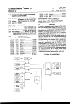
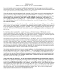
FIG. 1 is a high level block diagram showing the autono
mous vehicle system of the invention;
FIG. 2 is a ?ow chart illustrating the steps involved in
switching operation of a vehicle between manual and auto
40
modes of operation;
FIG. 3 is a block diagram illustrating the structure of the
machine control module of the invention;
FIG. 4 is a task diagram illustrating the operation and
organization of the machine control module of the invention;
FIG. 5 is a ?ow chart illustrating auto and manual
operation of an EPTC in accordance with the present inven
autonomous mode or a manual mode. The system includes
a machine control module, an engine control module, and a
transmission control module. In the autonomous mode, a
navigator produces a speed request signal and a steering
angle request signal for the vehicle. The machine control
module receives an auto/manual select signal from an opera
tor and the speed and steering angle request signals from the
tion; and
navigator. From these inputs, the machine control module
produces an engine RPM (revolutions per minute) control
signal, a transmission control signal, a brake control signal,
a steering angle control signal, and an auto/manual control
FIG. 6 is a How chart illustrating auto and manual
operation of an ADEM in accordance with the present
invention.
signal.
DETAILED DESCRIPTION OF THE
PREFERRED EMBODIMENT
I
The engine control module controls an RPM of the engine
of the vehicle in response to the engine RPM control signal
when the auto/manual control signal indicates autonomous
operation. When the auto/manual control signal indicates
manual operation, the engine control module controls engine
55
The preferred embodiment of the invention is discussed in
detail below. While speci?c part numbers and con?gurations
are discussed, it should be understood that this is done for
illustration purposes only. A person skilled in the relevant art
RPM in response to manual input from an operator, i.e.,
will recognize that other components and con?gurations
from an accelerator pedal similar to those found in automo 60 may be used without parting from the spirit and scope of the
biles.
invention.
The transmission control module controls gear selection
The preferred embodiment of the invention is now
in a transmission of the vehicle in response to the transmis
described with reference to the ?gures where like reference
sion control signal when the auto/manual control signal
numbers indicate like elements. In addition, the left-most
indicates autonomous operation. When the auto/manual con 65 digit of each reference number indicates the ?gure in which
trol signal indicates manual operation, the transmission
the number is ?rst used.
control module controls gear selection in response to opera
System Overview
5,469,356
3
4
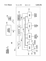
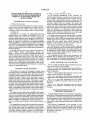
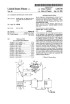
FIG. 1 is a high level block diagram showing an autono
mous vehicle system 100. Autonomous vehicle system 100
nostic information directly to navigator 120 over a data bus
includes a ?eet manager 102 and a vehicle control system
ADEM 128 controls the speed or RPM (revolutions per
minute) of the vehicle’s engine. EPTC 130 controls gear
154.
104. System 100 may also include a tele-operation panel 106
'
selection in the transmission and ensures that the transmis
sion is in the correct gear. VIMS 132 monitors different
systems of the vehicle. ADEM 128, EPTC 130 and VIMS
as discussed in further detail below.
Fleet manager 102 is con?gured to manage a ?eet of
autonomous mining vehicles such as dump trucks. Fleet
manager 102 acts like a foreman, assigning tasks to the
132 are available from Caterpillar Inc. of Peoria, Ill. In
mining vehicles and tracking their progress as they perform
these tasks. Fleet manager 102 communicates with each
addition, ADEM 128, EPTC 130 and VIMS 132 are avail
able as standard equipment on many of Caterpillar’s
vehicles. However, as discussed below, ADEM 128 and
EPTC 130 have been modi?ed in accordance with the
vehicle via a radio link 108. Each vehicle includes an -
on-board vehicle control system 104. Vehicle control system
104 permits autonomous operation of the mining vehicle
under the control of ?eet manager 102. Vehicle control
system 104 includes a navigator 120, a truck reference unit
(TRU) 122, an obstacle detector 124, a machine control
module (MCM) 126, and advanced diesel engine manager
(ADEM) 128, an electronic programmable transmission
control (EPTC) 130, and a vital information management
present invention to receive controlling inputs from MCM
15
Autonomous Operation
To achieve autonomous operation of the vehicle, the
steering angle request and the speed request from navigator
120 must be answered by adjusting the steering angle and
speed of the vehicle. MCM 126 compares the speed
requested by navigator 120 with the actual vehicle speed and
system (VIMS) 132.
Navigator 120 receives instructions from ?eet manager
102 via radio link 108. The instructions include, for
example, a work assignment or task. From the task, navi
adjusts the vehicle speed, if required, by sending appropriate
signals to ADEM 128, EPTC 130 and the vehicle’s braking
gator 120 determines a route to be followed. The route may
be, for example, a haul segment between an excavation site
and a crusher site in an open pit mining operation.
TRU 122 determines the actual position of the vehicle
25
using the global positioning system (GPS) and an inertial
reference unit (IRU). Based on the actual position and the
desired route, navigator 120 generates a desired steering
angle and a desired speed for the vehicle. Obstacle detector
126 as well as the standard operator inputs from an accel
erator pedal and a shift cane, respectively.
system. MCM 126 communicates these instructions to
ADEM 128 and EPTC 130 over a data link 134. In addition,
VIMS 132 monitors the status of ADEM 128 and EPTC 130
over and provides monitored parameters to MCM 126 over
data link 134. In the preferred embodiment, data link 134 is
a serial data bus such as a CAT Data Link, available from
30
Caterpillar Inc.
MCM 126 communicates an engine RPM control signal
to ADEM 128 over data link 134 to control engine speed. A
second engine RPM control signal is also sent to ADEM 128
124 is a radar unit which scans the area in front of the vehicle
for obstacles. When obstacle detector 124 detects an
over a redundant line 136.
obstacle, it provides an indication that an obstacle is detected
and/or the location of the obstacle to navigator 120. Navi 35
MCM 126 communicates a transmission control signal to
EPTC 130 over data link 134 to select the top gear and
gator 120 may then stop the vehicle or navigate around the
obstacle.
direction (i.e., forward or reverse) of the transmission. The
vehicle has an automatic transmission which is controlled by
Tele-operation panel 106 may be used to communicate,
EPTC 130. The transmission control signal limits the top
via radio signals as indicated at 110, steer angle, speed and
other commands directly to navigator 120 to allow remote
gear which may be used by the transmission and selects the
direction of travel for the vehicle.
control operation of the vehicle.
Examples of ?eet manager 102, tele-operation panel 106,
In conjunction with controlling vehicle speed, MCM 126
controls the braking system. In the preferred embodiment of
the invention, the vehicle braking system includes a parking
navigator 120, TRU 122 (also known as a “vehicle posi
tioning system”) and obstacle detector 124 are described in
detail in the ’540 application which is incorporated by
reference above. In addition, an example of tele-operation
panel 106 is described in commonly owned, allowed co
pending U.S. patent application Ser. Appl. No. 08/299,448,
45
brake, a service brake/retarder system, and a secondary
50
brake. The parking brake is a spring applied brake which
requires air pressure to be released. Conversely, the service
brake/retarder is spring released and requires air pressure to
be applied. The secondary brake is similar to the service
brake, but operates on a separate air reservoir. The parking
titled “Remote Control System and Method for an Autono
mous Vehicle,” ?led on even date herewith.
Navigator 120, TRU 122 and obstacle detector 124 rep
resent on-board intelligence for the vehicle which allows
brake is used for holding the truck when it is not in use and
effects only the rear wheels. The service brake/retarder acts
on both front and rear axles. The secondary brake actuates
the service brake on the front axle and the parking brake on
autonomous control commands to be generated in the form
of the speed and steering angle request signals. Before
autonomous operation can be achieved, however, these
55
the rear axle.
MCM 126 controls these different brakes directly via
commands or requests must be serviced.
The present invention services the steering and speed
requests, among others, to achieve autonomous (or simply
“auto”) operation. MCM 126 receives the steering and speed
control line 138 which actuates solenoid valves to control air
information for the vehicle system; (e.g., steering, brakes,
pressure in the three systems. For example, when navigator
120 requests a speed lower than the present speed, MCM
126 decides whether the lower speed should be achieved by
reducing engine RPM and/or by applying the service brakes.
If braking is required, MCM 126 applies the brake in a
dump body, engine, transmission, etc.) to navigator 120.
smooth manner to avoid locking up the wheels.
requests from navigator 120 over a data bus 152. Over this 60
same data bus, MCM 126 provides status and diagnostic
MCM 126 controls the vehicle with the aid of ADEM 128
and EPTC 130. MCM 126 provides monitoring and diag
65
In response to the steering angle request from navigator
120, MCM 126 directly controls the vehicle’s steering by
nostic information to navigator 120 with the aid of VIMS
sending right steer and left steer signals 140 to solenoids
132. In addition, VIMS 132 provides monitoring and diag
which control steering.
5,469,356
5
6
In the preferred embodiment of the invention, autono
erly (based on status information provided by MCM 126 and
VIMS 154), navigator 120 will send an auto mode signal
back to MCM 126. Upon receipt of the return auto mode
signal from navigator 120, MCM 126 will enter the autono
mous mode. This involves MCM 126 switching ADEM 128
and EPTC 130 into autonomous mode by placing the proper
mous vehicle system 100 is used to implement an autono
mous haulage system. Using a number of dump trucks (such
as the Caterpillar 777C), the haulage system is con?gured to
carry a material such as rock from an excavation site to a
crusher site. To permit fully autonomous operation of the
vehicle, MCM 126 controls other features of the vehicle,
such as dumping of the truck body. MCM 126 produces a
dump signal 142 which actuates the hydraulic system of the
vehicle to raise and lower the vehicle body. For safety
considerations, MCM 126 also controls auxiliary functions
of the vehicle such as the horn, lights and backup alarm via
signal on AMCL 150 (e.g., by pulling AMCL 150 low). The
vehicle controls (e. g., ADEM 128 and EPTC 130) will then
be ready to receive instructions from MCM 126, which in
turn waits to receive instructions from navigator 120.
Once the vehicle is in autonomous mode, it will not
switch back to manual mode until several conditions exist.
These conditions reduce the possibility of the vehicle com
an auxiliary control line 144.
Thus, during autonomous operation, MCM 126 indirectly
ing out of autonomous mode at an undesired time or
controls the engine and transmission via ADEM 128 and
EPTC 130. MCM 126 directly controls the vehicle’ s braking
condition, e.g., while the vehicle is in motion. Before the
systems, steering, body (i.e., raise or lower), lights (includ
ing head lights and autonomous operation strobe warning
lights), horn and back-up alarm.
Manual Operation
the following conditions must exist:
(1) vehicle speed is zero;
(2) parking brake is on;
(3) shift cane 146 is in neutral;
(4) engine RPM is at low idle; and
(5) both the ?rst and second auto/manual switches are in
vehicle can switch from autonomous mode to manual mode,
MCM 126 implements autonomous operation of a
vehicle. It is desirable, however, to also permit manual
operation of the vehicle. In a manual mode of operation, the
autonomous control features should be transparent and not
aifect normal functioning of the vehicle. Moreover, for
safety, switching between an autonomous mode of operation
and a manual mode of operation must be tightly controlled
25
so that the vehicle remains in control at all times. The
structure, and operation of MCM 126 which implements
these features of the invention are described below.
30
MCM 126 permits manual operation by relinquishing
the manual position.
When these conditions exist, MCM 126 will place ADEM
128 and EPTC 130 in manual mode via AMCL 150. MCM
126 will also de-actuate all solenoid drivers used to control
other functions of the vehicle, such as the body, auxiliary
functions, brakes and steering.
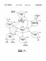
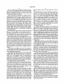
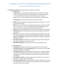
FIG. 2 is a simpli?ed block diagram illustrating the steps
followed in transitioning between manual operation and
control of the vehicle subsystems to an operator. In manual
autonomous operation. Manual operation is indicated at
block 202. Autonomous operation is indicated at block 214.
operator actuated throttle or accelerator pedal 144. Similarly,
As indicated above, manual operation 202 is the default of
EPTC 130 receives top gear selection and direction com 35 MCM 126 upon power-up. If it is desired to switch into the
mands from a shift cane 146 controlled by the operator.
autonomous operation mode and each of the conditions
mode, ADEM 128 receives the speed request signal from an
Brakes and steering are manually controlled by the operator
using a conventional steering wheel and brake pedal. The
listed above is met, MCM 126 will cycle through steps
204-212 before reaching autonomous mode 214.
First, in a step 204, a speed self-test is executed. The
body is controlled by a switch which actuates a solenoid in
the hydraulic system.
speed self-test checks data link 134 to assure that it is
operating properly and that ADEM 128 and EPTC 130 can
be controlled by MCM 126. In addition, MCM 126 checks
During manual operation, MCM 126 will continue to
monitor system parameters but will not interfere with con
trol of the vehicle in any way.
for brake pressure and assures that the brakes can be
Transitioning Between Manual and Autonomous Modes of
Operation
45
MCM 126 defaults to manual mode at power-up. Manual
mode is indicated to ADEM 128 and EPTC 130 via an
auto/manual select signal sent over an auto/manual control
line (AMCL) 150. For example, AMCL 150 is pulled HIGH
by ADEM 128 and EPTC 130. When AMCL 150 is high,
change in the steering angle can be sensed via position
sensors (not shown).
50
manual mode is indicated to ADEM 128 and EPTC 130. If
autonomous mode is desired, MCM 126 will indicate this to
55
(1) vehicle speed is zero;
(2) parking brake is on;
(3) shift cane 146 is in neutral;
(4) a ?rst auto/manual switch (located in the cab of the
vehicle) is switched to autonomous mode; and
(5) a second auto/manual switch (located near the ground
on, for example, the front bumper of the vehicle) is
In a step 208, a wait state is entered. In the preferred
embodiment, a ?ve second pause is executed. At the begin
ning of the pause, the horn is honked and strobe lights are
turned ON to want any person near the vehicle that autono
ADEM 128 and AMCL 150 by pulling AMCL 150 LOW.
Transition into autonomous mode will only take place if
the following conditions are met:
controlled. Next, in a step 206, a steering self-test is per
formed. In the steering self-test, the wheels of the vehicle are
moved to assure that steering can be controlled, and that the‘
mous operation is being enabled. Thereafter, the vehicle
enters a ready mode as indicated at step 210. In ready mode,
MCM 126 is in control of the speed and the steering of the
vehicle. The steering angle is set to zero degrees and the
speed is maintained at zero miles per hour. The vehicle will
remain in ready state until a valid command is received from
navigator 120.
60
Once a valid command is received, MCM 126 will enter
a second wait state as indicated at step 212. The second wait
state is similar to the ?rst. The horn is again honked and the
strobe lights remain on from the ?rst wait state. At the
switched to autonomous mode.
conclusion of this second wait state, autonomous mode
If these ?ve conditions are met, MCM 126 will send an auto 65 begins as indicated at step 214.
enable signal to navigator 120 over data bus 152. If navi
If the speed self test at step 204 or the steering self test at
gator 120 is satis?ed that all systems are functioning prop
step 206 fails, or if either of the auto/manual control
5,469,356
7
8
switches are toggled to manual mode during any of steps
208-212, MCM 126 will abort the changeover to autono
mous operation and will proceed directly to a step 216 which
performs an orderly transition back to manual operation 202.
The orderly transition or shut-down includes assuring that
the vehicle speed is zero, the parking brake is on, the
gator 120 as indicated by data bus 152. The second port is
an RS232 serial communications port available for diagnos
tic monitoring or debugging the operation of MCM 126 as
indicated by line 322. The third port is used for communi~
cations with data link 134 using a serial communications
protocol.
Low level output port 314 is used to connect AMCL 150
transmission is in neutral. The vehicle will stay in the
with MCM 126 and to provide the redundant throttle control
transition mode until both of the auto/manual control
to ADEM 128 via line 136. High level output module 316
switches are switched to manual mode. At this point, the
vehicle can then return to manual operation as indicated in 10 includes nine high current drivers to control the solenoids
step 202.
Operator Intervention in Autonomous Mode
which operate vehicle steering, brakes, body dumping, and
various auxiliary features.
In the event that an operator is present in the vehicle while
the vehicle is in autonomous mode, provisions have been
provided for receiving and acting on certain manual operator
inputs. An operator can alter the vehicles direction by
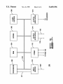
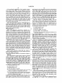
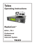
tion of the programs which run on processor 402 to imple
ment the features of MCM 126. MCM 126 includes a sensor
FIG. 4 is a task diagram illustrating structure and opera
task 402, a data link task 404, a speed task 406, a steering
task 408, an auxiliary task 410, a navigator communications
task 412 and an executive task 416.
manually operating the steering wheel. The cumulative
eifect on the steering angle will be dependent on the sum of
the steering commands coming from the operator and the
commands coming from MCM 126.
20
The operator will not be able to increase engine RPM.
Because ADEM 128 is in the autonomous mode, the accel
erator pedal will have no effect. Similarly, the operator will
not be able to change the transmission top gear, because the
shift cane position will be ignored by the EPTC 130. The
25
Sensor task 402 monitors various sensors on the vehicle
and places status information in a global data store (within
RAM 304) for use by other tasks in MCM 126. Sensor task
402 also provides the status information to executive task
416. Sensor task 402 receives much of its information from
VIMS 132 over data link 134. In addition to the information
received from VIMS 132, sensor task 402 monitors the ?rst
operator can stop the vehicle by placing the ?rst auto/manual
and second auto/manual switches on the vehicle as well as
control switch (the one located in the cab of the vehicle) into
the manual position. This causes MCM 126 bring the vehicle
several independent sensors which have been speci?cally
added to the vehicle to facilitate autonomous operation.
to a controlled stop on the path.
These include, for example, resolvers to sense steering
An operator can increase the vehicle’s deceleration by
30
brakes are being manually applied by the changes in pres
sure in the braking system and will begin to slow the vehicle.
Moreover, manual actuation of the service brake increases
35
the applied braking force.
MCM 126
FIG. 3 is a block diagram of MCM 126. MCM 126
includes a microprocessor 302 (e.g., a Motorola 68332
microprocessor), a random access memory (RAM) 304, an
angle.
Data link task 404 manages communications between
MCM 126 and ADEM 128, EPTC 130 and VIMS 132 over
data link 134. The information communicated over the data
link is provided to executive task 416 and speed task 406.
stepping on the service brake pedal or pulling on a retarder
handle within the vehicle cab. MCM 126 will detect that the
Speed task 406 generates the engine RPM control signal and
the transmission control signal which are communicated to
ADEM 128 and EPTC 130 via data link task 404. In
addition, speed task 406 directly controls the body of the
vehicle, over line 142, and the three braking systems of the
40
vehicle over line 138.
Vehicle speed is controlled in a closed loop fashion. When
speed requests are received from navigator 120, they are
compared to the actual vehicle speed as indicated in data
erasable programmable read only memory (EPROM) 306, a
?ash electrically erasable programmable read only memory
(EEPROM) 308, an input buffer 310, a communications
store 304. The actual vehicle speed as indicated in data store
module 312, a low level output driver 314 and a high level
output driver 316. Each of these modules is connected via a 45 304 is continuously updated by sensor task 402.
Steering task 408 controls the steering of the vehicle via 16 bit data bus 318. The programs which control operation
control line 140. Steering is controlled in a closed-loop
of MCM 126 are stored in EPROM 306 and are executed by
manner by comparing the steering angle indicated in data
microprocessor 302. EEPROM 308 is used to store param
store 304 with the requested steering angle received from
eters used by the programs. These parameters may be
navigator 120. Auxiliary task 410 controls auxiliary func
changed to tune MCM 126 for operation on different
tions of the vehicle such as the horn and lights via an
vehicles.
Input buffer 310 receives MCM input signals from the
auxiliary control line 144. Navigator communications task
various switches and sensors as indicated at line 309. For
412 communicates with navigator 120 over line 152 which
example, input buffer 310 receives a speed indication from
a vehicle odometer, auto/manual select signals from the
is a serial communications bus.
55
auto/manual control switches, and steering angle indications
from the steering angle sensors. Processor 302 receives the
various inputs from input buffer 310 by reading internal
latches of buffer 310 via bus 318. In addition, a bus 317
provides a direct connection between input buifer 310 and 60
input pins of processor 302. Bus 317 provides, for example,
frequency modulated and pulse width modulated (PWM)
Executive task 416 manages operation of all other tasks in
MCM 126. This involves controlling the transition between
autonomous and manual operation modes.
EPTC 130
Control of the actual transmission gear is performed by
EPTC 130. In the manual mode, the position of the cane
lever communicates to the EPTC 130 the desired direction
of travel in maximum allowable gear. EPTC 130 will shift
the transmission through the gears and up to the maximum
signals directly to a timer module of processor 302. Second
allowable gear as indicated by the shift lever. EPI‘C 130
RPM control signal 136 is an example of a PWM signal.
Communications module 312 implements three commu 65 receives the vehicle speed from VIMS 132 over data link
nications ports for MCM 126. The ?rst port is an RS232
134 to be used in applying its gear shifting strategy. For
serial communications port used to communicate with navi
additional information on manual operation of EPTC 130,
5,469,356
9
10
see Caterpillar Service Manual No. SENR5666, titled “Elec
If EPTC 130 is operating in manual mode, then the manual
tronic Programmable Transmission Control (EPTC H) For
ICM Transmissions,” May 1993, available from Caterpillar,
Inc., Peoria, 111., which is incorporated herein by reference.
shift lever or cane is checked for gear position at step 512.
The transmission is then shifted according to the normal
shifting algorithm of step 514. The method then returns to
step 506. As long as AMCL 150 continues to indicate
manual mode, EPTC 130 will continue to operate in this
loop in which gear selection is taken from the manual shift
When MCM 126 receives an autonomous mode request
from navigator 120, MCM 126 places ADEM 128 and EPTC
130 into the autonomous mode by grounding AMCL 150.
Once in the autonomous mode, EPTC 130 sends a broadcast
cane.
stop message to MCM 126 over data link 134. This message
If it is determined, at step 508, that this is the ?rst time
tells MCM 126 to stop communications with EPTC 130.‘ 10 AMCL 150 has indicated manual mode (i.e., a change from
MCM 126 responds by sending a broadcast stop acknowl
auto to manual is occurring), then the method proceeds to
edge message to EPTC 130 over data link 134. EPTC 130
step 530. At step 530, a broadcast stop message is transmit
then sends a broadcast request message to MCM 126 telling
ted to MCM 126 over data link 134 to initiate a change from
MCM 126 to send the transmission control signal. MCM
auto mode to manual mode as discussed above. At step 532,
126 responds by sending a broadcast request response
the remote gear select variable is checked to determine
message to EPTC 130 before sending the transmission
whether it indicates neutral. If neutral is not indicated, a fault
control signal. The transmission control signal is sent once
code indicating an invalid transition from auto mode to
per second.
manual mode is sent to MCM 126 over data link 134. Then,
This hand shaking between MCM 126 and EPTC 130
at step 536, the manual shift cane is checked to determine
prior to the transmission of control signals assures that the 20 whether it is in neutral. If neutral is indicated, then EPTC
communication link is functioning properly. If a failure in
130 is set to manual mode in step 538. If the cane does not
data link 134 occurs, EPTC 130 will assume a gear selection
indicate neutral, then the remote gear select variable is set to
of neutral. That is, the transmission will stay in the present
neutral and a fault code for an invalid transition is sent to
gear, or down shift when the vehicle speed so allows, until
MCM 126 over data link 134 at step 540. If, at step 510, it
the vehicle is stopped. When EPTC 130 detects a change on 25 is determined that EPTC 130 is in auto mode, then the
AMCL 150 (e.g., a request to change from autonomous to
method proceeds to step S36 and continues as discussed
above.
manual, mode), EPTC 130 will select a gear of neutral and
send out a broadcast stop request to MCM 126. MCM 126
Thus, when it is determined at step 506 that AMCL 150
will respond by sending a broadcast request response mes
sage. Then, if manual shift cane 146 is in neutral, EPTC 130
is indicating manual mode, EPTC 130 will take a desired top
30 gear indication from the manual shift cane as indicated at
will enter manual mode. If manual shift cane 146 is not in
step 512. Steps 508, 530, 532, 534, 536, 538, and 540 assure
neutral, EPTC 130 will hold the transmission in neutral and
will remain in that state until neutral is indicated by manual
that transition from auto mode to manual mode is done in an
orderly fashion as outlined above. These steps also ensure
shift cane 146. Any component problems detected by EPTC
130 are reported to VlMS 132 over data link 134.
35
These features of EPI‘C 131) are implemented by modi
fying the programmed microcode in EPTC 130. Microcode
is added to EPTC 130 which operates a layer above the
standard algorithm which controls shifting of the transmis
sion. The functionality of the additional microcode is illus
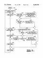
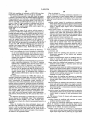
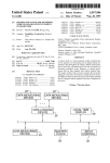
trated in the operational ?ow chart of FIG. 5 which presents
a loop which executes every 25 milliseconds.
In FIG. 5, normal operation of the transmission is indi
cated at step 514. All other steps/blocks of FIG. 5 implement
the features of the invention which allow EPTC 130 to
40
that a fault on AMCL 150 will not inadvertently place EPTC
130 in manual mode.
If, at step 506, it is determined that AMCL 150 indicates
autonomous operation, then the method proceeds to step
516. At step 516, it is checked to determine whether this is
the ?rst time that AMCL 150 has indicated autonomous
operation (i.e., a transition from manual to auto is occur
ring). If yes, then the method proceeds to step 518 where
EPTC 130 sends a broadcast request signal to MCM 126 to
initiate the signal handshaking (discussed above) which
45
operate in either a manual mode or an auto mode in
conjunction with MCM 126. These features are now
described with reference to the ?owchart.
assures proper functioning of the communication link
between MCM 126 and EPTC 130. In addition, at step 518,
EPTC 130 sets the remote gear select (RGS) variable to
neutral and sets the EPTC 130 mode to auto.
A remote gear selection is generally received three times
At power-up of EPTC 130, a reset occurs as indicated at
per second from MCM 126. This is tested at step 520. If a
step 502. After reset, the operating mode of EPTC 130 50 remote gear selection has not been received in the last three
defaults to manual and a remote gear select (RGS) variable
seconds, then a fault condition is indicated to MCM 126
is set to neutral as indicated at step 504. The remote gear
over data link 134 (CDL or Cat Data Link in FIG. 5) at step
select or RG8 variable is the transmission control signal
522. In addition, the remote gear select is set to neutral. The
received from MCM 136 over data link 134. EPTC 130
method then proceeds to step 514 where the transmission is
takes the transmission control signal and stores it in a 55 shifted in accordance with the standard shifting algorithm. If
memory location as a remote gear selection. When EPTC
a fault condition was indicated at step 522, then MCM 126
130 is in manual mode, gear selection is controlled by the
will reduce engine speed while the RGS of neutral causes
EPTC 130 to downshift until the transmission is in neutral
is controlled by RGS. '
and the vehicle can be stopped.
At step 506, AMCL 150 is checked. If AMCL 150 60 ADEM 128
shift cane. When EPTC 130 is in auto mode, gear selection
indicates manual operation, then the method proceeds to
step 508. In step 508, a check is made to determine whether
this is the ?rst time AMCL 150 is indicating manual mode
(i.e., a change from auto mode is occurring). If this is not the
?rst indication of manual mode, then the method proceeds to
step 510. At step 510, EPTC 130 is checked to determine
whether EPTC is actually operating in auto or manual mode.
65
ADEM 128 is responsible for governing the speed or
RPM of the vehicle’s engine. In manual mode, manual
throttle or accelerator pedal 144 provides an RPM request
which is compared to the actual RPM of the engine. ADEM
128 then adjusts injector fuel delivery to make the actual
RPM equal the desired RPM. For additional information on
manual operation of ADEM 128, see Caterpillar Electronic
5,469,356
11
12
Troubleshooting Manual No. SENR5l9l-02, titled “3508
EUI Engine,” June 1994, available from Caterpillar, Inc.,
Peoria, 111., which is incorporated herein by reference.
At step 606, AMCL 150 is checked. If AMCL 150
indicates manual operation, then the method proceeds to
step 608. In step 608, a check is made to determine whether
this is the ?rst time AMCL 150 is indicating manual mode
(i.e., a change from auto mode is occurring). If this is not the
?rst indication of manual mode, then the method proceeds to
step 610. At step 610, ADEM 128 is checked to determine
whether it is actually operating in auto or manual mode. If
ADEM 128 is operating in manual mode, then the manual
accelerator pedal is checked for position at step 612. The
engine RPM is then controlled according to the normal
engine RPM algorithm of step 614. The method then returns
When MCM 126 receives a autonomous mode indication
from navigator 120, MCM 126 places ADEM 128 into
autonomous mode via AMCL 150. Once in autonomous
1 mode, ADEM 128 will ignore the manual throttle control
and accept engine speed command signals from MCM 126.
MCM 126 computes a desired engine RPM based on the
speed request from navigator 120. The desired RPM is then
10
sent to ADEM 128 over data link 134. Similar to EPTC 130,
ADEM 128 handshakes signals with MCM 126 prior to
opening communications for RPM request signals. For
example, when ADEM 128 ?rst detects a manual-to-autono
to step 606. As long as AMCL 150 continues to indicate
manual mode, ADEM 128 will continue to operate in this
loop in which engine RPM is taken from the manual
mous status change request on AMCL 150, ADEM 128
enters autonomous mode and then sends a broadcast stop
command over data link 134. MCM 126 stops communica
accelerator pedal.
If it is determined, at step 608, that this is the ?rst time
AMCL 150 has indicated manual mode (i.e., a change from
auto to manual is occurring), then the method proceeds to
step 630. At step 630, a broadcast stop message is transmit
tions with ADEM 128 and responds to the, broadcast stop
command. MCM 126 then responds with a broadcast stop
acknowledgement message. ADEM 128 then sends a broad
cast request message, asking MCM 126 for RPM request
ted to MCM 126 over data link 134 to initiate a change from
auto mode to manual mode as discussed above. At step 632,
the DRPM variable is checked to determine whether it
once per second. ADEM 128 receives the speed request
indicates low idle or LI. If low idle is not indicated, a fault
signals from MCM 126 over the data link. In addition, 25 code indicating an invalid transition from auto mode to
manual mode is sent to MCM 126 over data link 134. Then,
however, a redundant speed request signal is also generated
by MCM 126 and sent to ADEM 128 over a dedicated wire
at step 636, the manual accelerator pedal is checked to
136. This redundant signal can be used by ADEM 128 if the
determine whether it is in a low idle position. If low idle is
signals. MCM 126 responds by sending a broadcast request
response message and then by sending desired RPM signals
speed request signal is not sent on data link 134. If both
signals are absent, ADEM 128 will set the engine to low idle
and communicate the loss of communications to VIMS 132.
When ADEM 128 detects the request to change from
autonomous to manual mode on AMCL 150, ADEM 128
sends a broadcast stop request to MCM 126 over data link
134. MCM 126 responds with a broadcast stop acknowl 35
edgement message. ADEM 128 then begins reading the
signal coming from the manual throttle 144. If the manual
throttle 144 requests low idle, ADEM 128 fully enters
manual mode. If the signal is not low idle, ADEM 128 will
stay in autonomous mode and set the speed at low idle and
variable is set to low idle and a fault code for an invalid
transition is sent to MCM 126 over data link 134 at step 640.
If, at step 610, it is determined that ADEM 128 is in auto
mode, then the method proceeds to step 636 and continues
as discussed above.
Thus, when it is determined at step 606 that AMCL 150
is indicating manual mode, ADEM 128 will take a desired
RPM from the manual accelerator pedal as indicated at step
612. Steps 608, 630, 632, 634, 636, 638, and 640 assure that
40
will not return fully to manual mode until manual throttle
144 indicates a speed of low idle.
FIG. 6 illustrates high level operation of ADEM 128
according to the invention. As with EPTC 130, ADEM 128
has been modi?ed to add microcode which operates a layer
above the standard algorithm which controls engine RPM.
The functionality of the additional microcode is illustrated in
the operational ?ow chart of FIG. 6 which presents a loop
which executes every 15 milliseconds. The remaining steps
of FIG. 6 implement the features of the invention which
allow ADEM 128 to be controlled by MCM 126.
In FIG. 6, normal operation of the engine is indicated at
step 614. All other steps/blocks of FIG. 6 implement the
features of the invention which allow ADEM 128 to operate
indicated, then ADEM 128 is set to manual mode in step
638. If the pedal does not indicate low idle, then the DRPM
transition from auto mode to manual mode is done in an
orderly fashion as outlined above. These steps also ensure
that a fault on AMCL 150 will not inadvertently place
ADEM 128 in manual mode.
45
If, at step 606, it is determined that AMCL 150 indicates
autonomous operation, then the method proceeds to step
616. At step 616, it is checked to determine whether this is
the ?rst time that AMCL 150 has indicated autonomous
operation (i.e., a transition from manual to auto is occur
ring). If yes, then the method proceeds to step 618 where
50
ADEM 128 sends a broadcast request signal to MCM 126 to
initiate the signal handshaking (discussed above) which
assures proper functioning of the communication link
between MCM 126 and ADEM 128. In addition, at step 618,
ADEM 128 sets the DRPM variable to low idle and sets the
in conjunction with MCM 126. These features are now 55 ADEM mode to auto.
described with reference to the ?owchart.
A DRPM signal is generally received three times per
At power-up of ADEM 128, a reset occurs as indicated at
second from MCM 126. This is tested at step 620. If a
step 602. After reset, the operating mode of ADEM 128
remote gear selection has not been received in the last three
defaults to manual and a desired RPM variable is set to low
seconds, then a data link fault condition is indicated to MCM
idle (LI) as indicated at step 604. The desired RPM variable
126 over data link 134 (CDL or Cat Data Link in FIG. 6) at
is the engine RPM control signal communicated to ADEM
step 622. Then, at step 624, the method checks to see
128 by MCM 126 over data link 134. ADEM 128 takes the
whether the second engine RPM control signal (a PWM or
engine control signal and stores it in a memory location as
pulse width modulated signal received from MCM 126 over
a desired RPM or DRPM. When ADEM 128 is in manual
line 136) is present at ADEM 128. If the second or PWM
mode, engine speed is controlled by the manual accelerator
pedal. When ADEM 128 is in auto mode, engine speed is
controlled by DRPM.
65
engine RPM control signal is present, then the method uses
the PWM signal as the DRPM at step 626. If the second or
PWM engine RPM control signal is not present, then a
5,469,356
13
14
PWM fault condition is indicated to MCM 126 over data
link 134 and the DRPM is set to low idle at step 628.
What is claimed is:
1. A system for controlling autonomous operation of a
vehicle in response to a speed request signal and a steering
The method then proceeds to step 614 where the engine
is shifted in accordance with the standard shifting algorithm.
If fault conditions were indicated at steps 622 and 628, then
ADEM 128 will reduce the engine speed to low idle as set
forth in step 628, and MCM 126 will cause the vehicle to
angle request signal from a navigator and for selectively
allowing manual operation of the vehicle, the system com
prising:
machine control means for receiving an auto/manual
come to a stop. If a fault condition is indicated only at step
622 and not step 628, then the vehicle may continue to
select signal, said speed request signal and said steering
angle request signal and for producing a speed control
signal, a steering angle signal, and an auto/manual
control signal;
speed control means for controlling the speed of the
operate using the second engine RPM control signal (the
PWM signal) to set the DRPM.
VlMS 132
Monitoring the status of the various vehicle systems is
vehicle in response to said speed control signal and an
provided by VIMS 132. VIMS 132 gathers information by
operator input when said auto/manual control signal
reading dedicated sensors on the vehicle and also by receiv
ing information from ADEM 128 and EPTC 130 over data
indicates autonomous operation and in response only to
said operator input when said auto/manual control
link 134. VIMS uses the collected information to determine
a machine warning level. The machine warning level indi
cates the highest fault level present on the vehicle. It
transmits this information directly to navigator 120 via line
154. VIMS 132 also provides this information to MCM 126
via data link 134. Navigator 120 may stop the vehicle by
sending a zero speed request to MCM 126. In addition, if a
serious fault condition exists, MCM 126 may stop the
vehicle directly.
Sample warning level indicators include the following:
signal indicates manual operation; and
steering control means for controlling the steering angle
20
of the vehicle in response to said steering angle control
signal and an operator input when said auto/manual
control signal indicates autonomous operation and in
response only to said operator input when said auto/
manual control signal indicates manual operation.
2. The system of claim 1, wherein said machine control
25 means comprises:
Level I: An example of a Level I warning is a ?uid level
out of normal operating range. In the case of a Level I
warning, the vehicle continues full autonomous opera
tion. However, the navigator indicates to the ?eet 30
manager that attention is needed to correct the condi
tion in due course.
a processor; and
program means for enabling said processor to control
autonomous operation of the vehicle said program
means including
navigator communications means for enabling said pro
cessor to receive said speed request signal and said
steering angle request signal from the navigator,
Level 11: An example of a Level II warning is an excessive
engine operating temperature. The Level II warning
sensor means for enabling said processor to receive a
indicates that a condition exists that will cause serious 35
measured steering angle, a measured speed and said
auto/manual select signal,
speed control signal means for enabling said processor to
generate said speed control signal, in response to said
speed request signal and said measured speed to control
damage to the vehicle if operation is not changed.
Level III: Examples of Level I[[ warnings include low air
pressure, low oil pressure and lack of coolant ?ow. In
the case of a Level III warning, the vehicle should be
stopped without delay. To accomplish this, navigator
40
120 commands MCM 126 to stop the vehicle imme
vehicle and for enabling said processor to control the
diately.
dumping of a body of the vehicle,
steering means for enabling said processor to generate
said steering angle control signal in response to said
The parameters monitored by VIMS 132 include, for
example, transmission charge ?lter, fuel ?lter, coolant flow,
steering ?ow, brake master cylinder overstroke, engine oil
an engine, a transrrrission and a brake disposed in the
45
level, transmission oil temperature, torque converter oil
steering angle request signal and said measured steer
ing angle,
temperature, after cooler temperature, brake oil temperature, ‘
data link means for enabling said processor to commu
primary system air pressure, secondary system air pressure,
steering fluid temperature, right turbo temperature, left turbo
nicate said speed control signal to an engine controller
disposed in the vehicle and to communicate said steer
temperature, cab air temperature, left rear strut pressure,
right rear strut pressure, left front strut pressure, right front
strut pressure, speed, gear position, parking brake, body
raise, engine RPM, engine oil pressure, atmospheric pres
ing control signal to a transmission controller disposed
in the vehicle, and
executive means for enabling said processor to supervise
sure, right turbo inlet pressure, jacket water temperature,
rack position, boost pressure, fuel ?ow, and air ?lter restric
control signal in response to said auto/manual select
said program means and to generate said auto/manual
signal.
tron.
3. The system of claim 2, wherein said program means
For additional information on VIMS 132, see Caterpillar
Service Manual No. SENR6059, titled “Vital Information
Management System (VIMS),” July 1993, available from
Caterpillar, Inc., Peoria, l1l., which is incorporated herein by
reference.
While the invention has been particularly shown and
described with reference to several preferred embodiments
thereof, it will be understood by those skilled in the art that
various changes in form and details may be made therein
without departing from the spirit and scope of the invention
as de?ned in the appended claims.
further comprises
60
auxiliary means for enabling said processor to control
auxiliary functions on the vehicle.
4. A system for controlling autonomous operation of a
vehicle in response to speed and steering angle request
signals from a navigator and for selectively allowing manual
operation of the vehicle, the system comprising:
65
machine control means for receiving an auto/manual
select signal, said speed request signal and said steering
angle request signal and for producing an engine RPM
5,469,356
16
15
autonomous operation of the vehicle, said program
control signal, a transmission control signal, a brake
control signal, a steering angle control signal, and an
means including
auto/manual control signal;
navigator communications means for enabling said pro
cessor to receive the speed request signal and the
engine RPM control means for controlling an RPM of a
vehicle engine in response to said RPM control signal
when said auto/manual control signal indicates autono~
mous operation and in response to an operator input
steering angle request signal from the navigator, p1
sensor means for enabling said processor to receive a
measured steering angle, a measured speed and an
when said auto/manual control signal indicates manual
auto/manual select signal,
operation; and
transmission control means for controlling a gear selec 10
tion in a vehicle transmission in response to said
transmission control signal when said auto/manual con
trol signal indicates autonomous operation and in
5. The system of claim 7, wherein said machine control
means comprises:
a processor; and
program means for enabling said processor to control 20
autonomous operation of the vehicle, said program
means including
response to the speed request signal to adjust gear
25
sensor means for enabling said processor to receive a
measured steering angle, a measured speed and said
'
speed control means for enabling said processor to gen
erate said RPM control signal, said transmission con 30
trol signal and said brake control signal in response to
said speed request signal and said measured speed,
steering angle request signal and said measured steer
said speed control means includes
means for generating an engine RPM request signal in
response to the speed request signal to adjust the RPM
of an engine disposed in the vehicle,
means for generating a transmission control signal in
navigator communications means for enabling said pro
cessor to receive said speed request signal and said
steering means for enabling said processor to generate
said steering angle control signal in response to said
signal,
vehicle speed in response to the speed request signal
and said measured speed only when said auto/manual
control signal indicates autonomous operation, wherein
control signal indicates manual operation.
auto/manual select signal,
said program means and to generate an auto/manual
control signal in response to said auto/manual select
speed control means for enabling said processor to control
response to an operator input when said auto/manual
steering angle request signal from the navigator,
executive means for enabling said processor to supervise
selection of a transmission disposed in the vehicle, and
means for generating a brake control signal in the vehicle
in response to the speed request signal to decrease the
speed of the vehicle by applying a braking action on a
brake disposed in the vehicle, and
steering means for enabling said processor to control
vehicle steering in response to the steering angle
request signal and said measured steering angle only
when said auto/manual control signal indicates autono
35
ing angle, and
mous operation.
9. The system of claim 1, wherein said program means
further comprises:
‘data link means for enabling said processor to commu
executive means for enabling said processor to supervise
said program means and to generate said auto/manual
control signal in response to said auto/manual select 40
signal.
6. The system of claim 5, wherein said program means
further comprises:
nicate said engine RPM request signal to an engine
controller disposed in the vehicle and for enabling said
processor to communicate said transmission control
signal to a transmission controller disposed in the
vehicle.
10. The system of claim 9, wherein said speed control
means further comprises:
nicate said engine RPM control signal to said engine 45
means for controlling a dump position of a body of said
RPM control means and for enabling said processor to
vehicle.
communicate said transmission control signal to said
11. The system of claim 10, wherein said program means
data link means for enabling said processor to commu
further comprises:
transmission control means.
7. The system of claim 6, wherein said program means
further comprises:
auxiliary means for enabling said processor to control
auxiliary functions on the vehicle.
8. A system for controlling autonomous operation of a
vehicle in response to a speed request signal and a steering
angle request signal generated by a navigator, comprising:
a processor; and
program means for enabling said processor to control
50
auxiliary means for enabling said processor to control
auxiliary functions on the vehicle.
12. The system of claim 5, wherein said auxiliary means
comprises:
means for switching power to lights disposed in the
vehicle; and
means for sounding a horn disposed in the vehicle.
UNITED STATES PATENT AND TRADEMARK OFFICE
CERTIFICATE OF CORRECTION
PATENT N0. :
DATED
INVENTOMS) :
5 ,469 ,356
November 21 , 1995
Mark R. Hawkins et al
It is certi?ed that enor appears in the above-identified patent and that said Letters Patent is hereby
cnnected as shown below:
a
Claim 5, column 15, line 16:
change "7" to --4—~—.
Claim 8 , Column 16 , line 6 , delete "pl".
Claim 9, column 16, line 34:
Claim 12, column 16, line 51:
change "1" to --8—-.
change "5" to ——1l--.
Signed and Sealed this
Twenty-fourth Day of September, 1996
BRUCE LEHMAN
AffeSting Officer
Commissioner of Patents and Trademark: