1
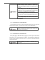
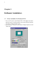
GM-184AS
Operating Manual
Ver. 1.1
Preface
This manual provides some information on precautions and operation that you should be
aware of prior to using GM-184AS. Improper usage of this product can result in an accident.
To ensure correct usage of GM-184AS, please be sure to read this manual prior to use. After
reading this manual, please keep it as a reference.
Safety Precautions
FCC Information
• FCC (U.S. Federal Communications Commission)
This equipment has been tested and found to comply with the limits for a Class A digital device, pursuant to Part 15 of the FCC Rules. These limits are designed to provide
reasonable protection against harmful interference when the equipment is operated in a
commercial environment.
This equipment generates, uses, and can radiate radio frequency energy and, if not installed and used in accordance with the instruction manual, may cause harmful interference to radio communications. Operation of this equipment in residential area is likely to
cause harmful interference in which case the user will be required to correct the interference at his own expense.
The Responsible Party located within United States TOTOKU North America, Inc.
27 Concord Street, El Paso, TX
79906-4953, United States
TEL: (915)-788-6606
CE Certification
• This device complies with the requirement of the MDD directive 93/42/EEC ”Medical Device Directive”.
Foreign Matter
• Do not spill liquids or drop flammable substances or metal on the board. Foreign matter
may cause a fire, electrical shock or breakdown.
Static Electricity
•
•
•
•
Board consists of precision parts. Please handle the board with extreme care.
Please be sure not to throw it on the carpet or plastic case.
Never touch edge connector portion of the board by hands.
In the case that the board is not used for a long time of period, please put it in the original
static proof bag that this board was sealed in and store in a safe place.
Impact
• This machine contains highly sensitive equipment. Impact to the machine may cause a
breakdown. Please be extremely careful when moving the machine.
3
Contents
Chapter 1
Hardware Installation
4
1.1
Summary of Hardware . . . . . . . . . . . . . . . . . . . . . . . .
4
1.2
Required System . . . . . . . . . . . . . . . . . . . . . . . . . . .
4
1.3
Connection to LCD Monitor . . . . . . . . . . . . . . . . . . . . .
5
1.4
Connection to VGA Device . . . . . . . . . . . . . . . . . . . . . .
5
Software Installation
6
2.1
Driver Installation for Windows NT4.0 . . . . . . . . . . . . . . . .
6
2.2
Driver Installation for Windows 2000 . . . . . . . . . . . . . . . .
10
Display Setting
13
3.1
Display resolution and monitor layout . . . . . . . . . . . . . . . .
13
3.2
Multi-display (Only for Windows 2000) . . . . . . . . . . . . . . .
16
3.3
VGA Input Indication Function . . . . . . . . . . . . . . . . . . . .
16
Types of Palette
19
4.1
Types of Palette . . . . . . . . . . . . . . . . . . . . . . . . . . . .
19
4.2
Palette Setting . . . . . . . . . . . . . . . . . . . . . . . . . . . . .
21
4.3
Precautions when setting palette . . . . . . . . . . . . . . . . . .
22
Chapter 2
Chapter 3
Chapter 4
Appendix A Specification
23
A.1
General Specification . . . . . . . . . . . . . . . . . . . . . . . . .
23
A.2
Specification of Input and Output . . . . . . . . . . . . . . . . . .
24
A.3
Standard . . . . . . . . . . . . . . . . . . . . . . . . . . . . . . . .
24
A.4
Accessories . . . . . . . . . . . . . . . . . . . . . . . . . . . . . .
24
4
Chapter 1
Hardware Installation
1.1 Summary of Hardware
GM-184AS is a PCI board type gray scale graphics board compatible with 3M pixel
LCD Monitor, ME311L made by TOTOKU Electric. Co., Ltd. One board of PCI bus
half size single board can display 2 or 1 monitors.
1.2 Required System
Processor
:
Pentium III 500MHz or up is recommended.
Memory
:
128MB minimum. 256MB or up is recommended.
512MB minimum for multi-board use.
OS
:
Windows NT4.0 Service Pack 4 or up / Windows 2000
VGA Device
:
Device with Video BIOS mounted.
(AGP/PCI Video Card, On Board Video, etc.)
1.2.1 Installation
For the GM-184AS to perform correctly, the following conditions must be met.
Since GM-184AS is to be installed in the PC, make sure that the operating environment and rating of the PC meet the requirements.
1. Turn off power to the PC and remove the cover. Follow the instructions in the PC
manual.
2. It should be inserted firmly into the PCI back plane. Fix using the fitting metal
screws that came with the GM-184AS.
3. Install the cover following the instructions in the PC manual.
5
When installing a board, qualified PC system engineers must change the system, or the system may not
start up.
Before starting to work, make back-ups of all software
(hard disc). Even in the case that the GM-184AS board
has errors, our company will not be held liable.
Before touching any board, touch a metal portion of the
PC (such as PC cover) to discharge any static electricity.
Do not change setting of DIP switches (all off) mounted
on the board.
1.3
Connection to LCD Monitor
Connect HEAD1 with monitor on the left and HEAD2 with monitor on the right with
enclosed monitor cables. (If you have one monitor, connect with HEAD1.)
Before connecting GM-184AS with CRT monitor, turn
off power to all equipment.
1.4
Connection to VGA Device
During PC start-up, GM-184AS has a function to convert output of VGA device
and output to CRT monitor connected to HEAD1. If you would like to validate this
function, connect output of VGA device on PC to VGA-IN of GM-184AS using the
enclosed VGA cable.
Before connecting VGA device to GM-184AS, turn off
PC power.
6
Chapter 2
Software Installation
2.1 Driver Installation for Windows NT4.0
1. Turn on the PC power to start Windows NT4.0. After logging in the system,
right-click mouse in an arbitrary position on the screen and select Properties.
The window of ”Display Properties” opens.
2. Select the dialog of ”Settings” from the window of ”Display Properties” and click
”Display Type.”
7
3. The dialog of ”Display Type” opens. Click ”Change” of ”Adapter Type.”
4. The dialog of ”Change Display” opens. Click ”Have Disk· · ·.”
8
Chapter 2 Software Installation
5. The dialog of ”Install From Disk” opens. Insert GM-184AS Display Driver into
the floppy disk drive, set ”A:\” in the box of ”Copy manufacturer’s files from:” and
click ”OK.”
6. The dialog of ”Change Display” opens. Select ”GM-184AS Windows NT 4.0” and
click ”OK.”
9
7. The dialog of ”Third-party Drivers” opens. Click ”Yes” to continue.
8. After installation completes, the dialog of confirmation to restart the system is
indicated. Select ”Yes” to restart the system.
10
Chapter 2 Software Installation
2.2 Driver Installation for Windows 2000
1. Turn on the PC power to start Windows 2000. After logging in the system, the
window of ”Found New Hardware Wizard” opens. Click ”Next.”
2. The window of ”Install Hardware Device Drivers” opens. Select ”Search for a
suitable driver for my device [recommended]” and click ”Next.”
11
3. The window of ”Locate Driver Files” opens. Insert GM-184AS Display driver into
the floppy disk drive, set ”Optional search locations:” to ”Floppy disk drives, ” and
click ”Next.”
4. The window of ”Driver Files Search Results” opens. Click ”Next.”
12
Chapter 2 Software Installation
5. The dialog of ”Digital Signature Not Found” opens. Click ”Yes” to continue the
installation.
6. The window of ”Completing the Found New Hardware Wizard” opens. Click
”Finish.”
7. Restart the system.
13
Chapter 3
Display Setting
3.1
Display resolution and monitor layout
Up to 4 GM-184AS can be used in one PC simultaneously.
∗1
Combination of
display resolution and monitor layout to be selected differs depending on your OS and
the number of GM-184AS you are using. As for compatibility between each board
and monitor layout, it depends on the PC you use, so please check by connecting
with your PC. DIP switches of all boards should have the same setting.
3.1.1 Windows NT4.0
On Windows NT4.0, display resolution and monitor layout to be selected is determined in accordance with the number of pieces which are used simultaneously.
Please refer to the Figure 3.1 for possible combinations to be selected. To change the
display resolution, right click in the background of desk top and select ”Properties” or
select ”Start”→”Settings”→”Control Panel”→”Display” then property window shown
in the Figure 3.2 will open. Press ”Settings” tab and slide control bar of ”Desktop
Area”
3.1.2 Windows 2000
On Windows 2000, as shown in the Figure 3.3, display resolution and monitor
layout on one GM-184AS is fixed, but display layout between boards can be set
freely using the multi-display function of Windows 2000. To change the display resolution, right click in the background of desk top and select ”Properties,” or select
”Start”→”Settings”→”Control Panel”→”Display”, then property window as shown in
the Figure 3.2, will open. Press ”Settings” tab and slide control bar of ”Screen area”
∗1
You may not be able to use the maximum number of GM-184AS depending on PC resource or OS configuration.
14
Chapter 3 Display Setting
Board number
1
2
Monitor layout and setting resolution
1536 × 2048
1536 × 4096
2048 × 1536
2048 × 3072
3072 × 2048
4096 × 1536
3072 × 4096
4096 × 3072
4608 × 2048
6144 × 1536
6144 × 2048
8192 × 1536
3
4608 × 4096
6144 × 3072
6144 × 4096
8192 × 3072
4
Figure 3.1: Monitor layout and setting resolution on Windows NT4.0
15
Windows NT4.0
Windows 2000
Figure 3.2: Display Properties
Monitor layout and setting resolution
1536 × 2048
1536 × 4096
2048 × 1536
2048 × 3072
3072 × 2048
4096 × 1536
Figure 3.3: Monitor layout and setting resolution on Windows 2000
16
Chapter 3 Display Setting
3.2 Multi-display (Only for Windows 2000)
When using the multi-display function on Windows 2000, check ”Extend my Windows desktop onto this monitor” for each VGA device and GM-184AS. If the monitor
output of your VGA device is connected to GM-184AS, please make sure to remove
the check mark ”Extend my Windows desktop onto this monitor” Please refer to the
3.3 VGA input indication function for details.
3.3 VGA Input Indication Function
Video BIOS is not installed in GM-184AS, so you need VGA device which has
video BIOS. GM-184AS has VGA input indication function to show a screen, which
VGA device outputs, on LCD monitor while Windows starts up, but handling of VGA
device differs as follows depending on the operating system you use. Please conduct
a setting in accordance with purpose of use.
When a LCD monitor is set vertically, a VGA image is
indicated properly.
When a LCD monitor set horizontally, a VGA image is
turned 90 degree and indicated.
17
3.3.1 Windows NT4.0
After GM-184AS software installation, Windows screen is drawn only on GM184AS. Only a screen during activation is drawn on your VGA device, and the screen
becomes blue back display after Windows NT 4.0 started up. Connecting monitor
output of VGA device with GM-184AS enables to show the screen during activation
on the LCD monitor.
Figure 3.4: Example of displays when VGA device output is connected to VGA monitor
Figure 3.5: Example of displays when VGA device output is connected to GM-184AS
18
Chapter 3 Display Setting
3.3.2 Windows 2000
Connecting monitor output of VGA device with VGA monitor enables drawing Windows screens on both of GM-184AS and your VGA device.
∗2
In the case that you do
not draw screen on VGA device, screen during activation can be shown on the LCD
monitor by connecting monitor output of VGA device with GM-184AS. After Windows
2000 started up, the screen switches to GM-184AS display automatically.
∗3
Figure 3.6: Example of displays when VGA device output is connected to VGA monitor
Figure 3.7: Example of displays when VGA device output is connected to GM-184AS
∗2
∗3
Some color setting combinations of VGA device and GM-184AS can result in display malfunction. Please
refer to 4.3 Precautions when setting palette for details.
Set up a VGA device invalidly with properties of the screen in advance before you connect the output of the
VGA device to GM-184AS because the screen of the VGA device isn’t indicated after the Windows2000
start. ( ”Extend my Windows desktop onto this monitor” is invalidated. )
19
Chapter 4
Types of Palette
4.1
Types of Palette
There are the following 3 types for GM-184AS palette.
• Dynamic gray palette with system color
• Static gray palette with system color
• Static gray palette in a Linear
Default setting of palette is dynamic gray palette with system color. Dynamic gray
palette with system color corresponds to System color, and its palette form is a standard form which is formed by Windows.
4.1.1 Dynamic gray palette with system color
The first 10 colors (No.
0 to No.
9) and the last 10 colors (No. 246
to No. 255) among 256 colors are
offered to window color prescribed
by OS as system color.
As for
the remaining 236 colors (No.10 to
No.245), palette content is changeable as necessary.
It becomes a
standard palette form as formed by
Windows.
20
Chapter 4 Types of Palette
4.1.2 Static gray palette with system color
The first 10 colors (No. 0 to No. 9)
and the last 10 colors (No. 246 to
No. 255) among 256 colors are offered to window color prescribed by
OS as system color. The remaining
236 colors (No.10 to No.245) make
gray scale by colors which are not
used for system color.
4.1.3 Static gray palette in a Linear
All 256 colors of palette make gray
scale. Since it does not offer palette
to system color, the display which
used system color System color
changes color.
21
4.2
Palette Setting
After display drive installation, it is possible to switch to each palette mode with GM184AS shown on the Control Panel. Change of the palette mode becomes effective
after the restart of the PC is done.
Control panel
ASTRO palette mode setting
Figure 4.1: Palette mode setting
22
Chapter 4 Types of Palette
4.3 Precautions when setting palette
Please set pallet and screen property as follows in order to make 256 color gray
scale displayed.
1. Pallete Setting
Set to Static gray palette in a Linear.
2. Screen Property Setting
For multi-display, set gray scale monitor to primary and set VGA monitor to 16 or
more colors.
However, this pallet setting is different from standard setting on Windows (Dynamic
gray palette with system color) and may cause the following problems.
1. If the application (viewer, browser, etc.) does not contain a specification of 256
color gray scale display, the image may appear unnatural.
2. When using the function of multi-display, images on browser (IE, Netscape) may
appear unnatural not only on a gray scale monitor but on VGA monitor.
These problems occur because Windows and normal applications (viewer, browser,
etc.) do not consider 256 color gray scale display in 256 color mode.
23
Appendix A
Specification
A.1
General Specification
Dot Clock
65MHz × 4 parallel
Refresh Rate
60Hz
1HEAD
Display Resolution
Portrait
1536 × 2048
Landscape
2048 × 1536
Portrait
2HEAD
Landscape
Number of Connecting
1536 × 4096
3072 × 2048
2048 × 3072
4096 × 1536
2 or 1
Monitors
Display Bit
8 bit/pixel
Display Memory
32 MB SDRAM
Look Up Table
8 bit input, 10 bit output
Bus Interface
PCI Version 2.1
Compatible Monitor
ME311L made by TOTOKU Electric. Co., Ltd.
Video Output
GVIF
VGA Display
Scan converted and displayed on ME311L
24
A.2
Appendix A Specification
Specification of Input and Output
Monitor Output
Connector
3M 10214-1210VE
Compatible
TOTOKU Electric. Co., Ltd. PZE29-07
Cable
VGA Input
Connector
High density D-SUB 15 pin
Compatible
TOTOKU Electric. Co., Ltd. PZE25-11
Cable
A.3
Standard
Slot
PCI 1slot ( Conforms to PCI Bus Specification Revision 2.1)
Size
172.7×106.7mm (PCI Short Size)
Weight
Approximately 0.22Kg
Operating Temperature
10 ∼ 35 ◦ C
Storage Temperature
-10 ∼ 60 ◦ C
Humidity
30 ∼ 85%RH (No condensation is allowed)
Power Consumption
10VA MAX
A.4
Accessories
Operating Manual
1 copy
GM-184AS Display Driver
1
(Compatible with Windows NT4.0/Windows 2000)
(Floppy Disk)
25
Notes
• Copyright of this board and software is held by ASTRODESIGN, Inc.
• If any pages are missing or out of order, we will exchange the manual.
• A portion or all of this software or operating manual cannot be used or copied
without our permission.
• Content of this manual is subject to change without prior notice due to improvement.
• We are not responsible for problems resulting from improper use of this product.
• If you have any questions of this product, please contact a distributor or our
company.
• Products and product names described in this operating manual are trade name
and trademark for each company.
• Windows NT4.0 and Windows 2000 are trademarks of Microsoft.
GM-184AS Operating Manual
Sales and Marketing Division
2002. 12. 14
2-6-17 Haramachi, Meguro-ku,
Tokyo, Japan 152-0011
Phone: 81-3-5720-5838
Fax: 81-3-5720-6353