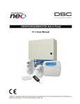
1
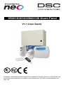
HS2016/2032/2064/2128 Alarm Panel
V1.1 User Guide
WARNING: This manual contains information on limitations regarding product use and function and information on the limitations as to liability of the manufacturer. The entire manual should be carefully read.
Table of Contents
1.0 Quick Reference
2.0 Understanding your Keypad
2.1 Icon and LED Keypad Symbols
2.2 Keypad Models
3.0 The PowerSeries Neo Security System
3.1 General System Operation
3.2 Testing your System
3.3 Monitoring
3.4 Maintenance
4.0 Arming the System
4.1 Away Arming the System with the Keypad
4.2 Exit Delay Time Restart
4.3 Alarm Cancel Window
4.4 Using 2-way Wireless Keys and Proximity Tags
4.4.1 Arming the system with a 2-way wireless key
4.4.2 Arming the System with a Proximity Tag
4.5 Disarming the System
4.5.1 Disarming Error
5.0 Emergency Keys
6.0 Access Code Types
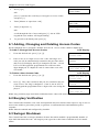
6.1 Adding, Changing and Deleting Access Codes
6.2 Burglary Verification
6.3 Swinger Shutdown
6.4 Call Waiting
6.5 Fire Alarm Verification
6.6 System Lockout due to Invalid Attempts
6.7 User Labels (LCD keypads only)
7.0 Trouble Conditions
8.0 Safety Instructions
8.1 Regular Maintenance and Troubleshooting
8.1.1 Cleaning
8.1.2 Troubleshooting
8.0 Reference Sheets
8.2 System Information
8.3 Service Contact Information
8.0 Regular Maintenance and Troubleshooting
8.4 Cleaning
8.5 Access Code and Sensor/Zone information
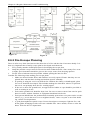
8.6 Locating Detectors and Escape Plan
8.6.1 Smoke Detectors
8.6.2 Fire Escape Planning
8.6.3 Carbon Monoxide Detectors
9.0 Regulatory Agency Statements
1
3
3
4
5
5
5
6
6
7
7
8
8
8
8
8
9
9
10
11
12
12
12
13
13
13
13
16
21
21
21
21
22
22
23
23
23
23
26
26
27
28
29
Chapter 1.0 Quick Reference
1.0 Quick Reference
The PowerSeries Neo Alarm System uses shortcut keys to access options or features on all models
of keypads. When using an LCD keypad, the PowerSeries Neo Alarm System additionally uses a
menu based navigation system. The scroll keys can be used to [Scroll] through the list of options contained within the current menu. For more information on keypads see 2 “Understanding your
Keypad Display”. Lookup detailed information on any of the listed actions using the accompanying
Section number.
For detailed information about the PowerSeries Neo Alarm System, refer to the full online manual,
with the following part #: 2900861R001, which can be accessed from the DSC.com Web site.
Note: Some features must be enabled by installer.
Note: Bypass Groups are not permitted in UL listed installations.
Note: [*] - If configured by installer
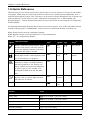
Status
Emergency Status Function Emergency
Function Keys
Lights
Keys
Lights Keys
Keys
Ready - Indicates system normal. Must
be on to arm system. All zones must be
secured or bypassed and the system disarmed for this light to activate.
Stay
Arm
Fire Alarm
Armed- Indicates system is armed. If the
Ready light and the Armed light are both
on, an Exit Delay is in progress.
Away
Arm
Medical
Alarm
Trouble - On indicates a system malfunction or tamper. Flashing indicates
that the keypad has a low battery condition. Follow the instructions displayed
or enter [*][2] to view trouble. Correcting the trouble turns off the indicator.
Chime
Panic Alarm
AC Power - Indicates AC Power is
present. The AC Power light will turn
off when AC is absent.
Reset Sensors
Quick
Exit
Action
Press
Arming and Disarming
Away Arm
Stay Arm
for 2 seconds + [Access Code*]
for 2 seconds + [Access Code*]
Night Arm
When armed in stay mode [*][1] + [Access Code*]
Disarm
[Access Code]
No-Entry Arming
[*][9] + [Access Code*]
-1-
Chapter 1.0 Quick Reference
Action
Press
Quick Arm/Quick Exit
[*][0]
Abort Arming Sequence
[Access Code]
Bypassing - All bypass commands begin with [*][1] + [Access Code*]
Bypass Individual Zones
[3 Digit Zone #]
Bypass All Open Zones
[9][9][8]
Recall Last Bypass
[9][9][9]
Clear Bypass
[0][0][0] OR [Scroll] Bypass Options + [*] + [Scroll]
Clear Bypasses + [*]
Program Bypass Group
[3 digit zone #s] + [9][9][5] OR [3 digit zone #s] +
[Scroll] Bypass Options + [*] + [Scroll] Prg Bypass
Group + [*]
Load Bypass Group
[9][9][1] OR [Scroll] Bypass Options + [*] + [Scroll]
Bypass Group + [*]
Common Functions
Set Time and Date
[*][6] [Master Code] + [0][1]
Turn Chime ON/OFF
[*][4] + [Access Code*] OR
Change Brightness
Change Contrast
Add/Delete User
Reset Smoke Detectors
View Troubles
View Alarms
Perform System Test
Buzzer Volume
[*][6] [Master Code] + [1][2] +
[*][6] [Master Code] + [1][3] +
[*][5] + [Master Code] + [Access Code] + 1
OR [*][7][2]
[*][2] + [Access Code*] +
[*][3] + [Access Code*] +
[*][6] + [Master Code] + [0][4] +
[*][6] + [Master Code] + [1][4] +
-2-
Chapter 2.0 Understanding your Keypad
2.0 Understanding your Keypad
The PowerSeries Neo Alarm System supports a variety of wireless, hardwired and proximity
sensor LCD, LED and Icon keypads. All keypads come equipped with the LED status lights
described in section 1 "Quick Reference". HS2LCD series keypads display system messages on
their LCD screen. HS2ICN series keypads display messages as described in 2.1 “Icon and LED
Keypad Symbols”. HS2LED series keypads display messages via a series of numbered LEDs as
described in 2.1 “Icon and LED Keypad Symbols”.
All keypad versions will have a solid blue LED bar that is always on steady except when, if
enrolled, a proximity tag is presented to and successfully read by the keypad.
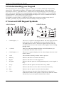
2.1 Icon and LED Keypad Symbols
HS2ICN Series
5
9
HS2LED Series
1
2
3
4
6
9
15
5
16
7
17
14
12
7
11
8
10
6
13
1.
Clock Digits 1, 2
These two 7 segment clock digits indicate the hour digits when the
local clock is active, and identify the zone when the OPEN or
ALARM icons are active. These two digits scroll one zone per
second from the lowest zone number to the highest when scrolling
through zones.
2.
: (Colon)
This icon is the hours/minutes divider and will flash once per
second when the local clock is active.
3.
Clock Digits 3, 4
These two 7 segment displays are the minute digits when the local
clock is active.
4.
1 to 8
These numbers identify troubles when is pressed.
5.
Memory
Indicates that there are alarms in memory.
6.
Bypass
Indicates that there are zones bypassed.
7.
Program
Indicates that the system is in Programming mode, or the keypad is
busy.
8.
Away
Indicates that the panel is armed in the Away Mode.
9.
Fire
Indicates that there are fire and/or CO alarms in memory.
10.
Stay
Indicates that the panel is armed in the Stay Mode.
11.
Chime
This icon turns on when the Chime function key is pressed to
enable Door Chime on the system. It will turn off when the chime
function key is pressed again to disable Door Chime.
-3-
Chapter 2.0 Understanding your Keypad
12.
OPEN
This icon is used with clock digits 1 and 2 to indicate activated
zones (not alarm) on the system. When zones are opened, the
OPEN icon will turn on, and 7 segment displays 1 and 2 will scroll
through the violated zones.
13.
AC
Indicates that AC is present at the main panel.
14.
System Trouble
Indicates that a system trouble is active.
15.
Night
Indicates that the panel is armed in the Night Mode.
16.
Ready Light (green)
If the Ready light is on, the system is ready for arming
17.
Armed Light (red)
If the Armed light is on, the system has been armed successfully.
Note: For UL listed installations, zones can only be bypassed manually.
2.2 Keypad Models
Note: In the following list if x = 9 (the system operates in 912-919MHz), x=4 (the system operates
in 433MHz band) or x=8 (the system operates in 868MHz band). Only models operating in 912919MHz band are UL/ULC listed.
HS2LCD
Alphanumeric LCD keypad
HS2LCDP
Alphanumeric LCD keypad with Prox. Tag support
HS2ICN
Icon keypad
HS2ICNP
Icon keypad with Prox. Tag support
HS2LED
LED keypad
HS2LCDRFx
Alphanumeric LCD keypad with wireless receiver
HS2LCDRFPx
Alphanumeric LCD keypad with wireless receiver and Prox. tag support
HS2ICNRFx
Icon keypad with wireless receiver
HS2ICNRFPx
Icon keypad with wireless receiver and Prox. tag support
HS2LCDWFx
Wireless Alphanumeric LCD keypad
HS2LCDWFPx
Wireless Alphanumeric LCD keypad with Prox. Tag support
HS2LCDWFPVx Wireless Alphanumeric LCD keypad with Prox. Tag support & Voice Promp
-4-
Chapter 3.0 The PowerSeries Neo Security System
3.0 The PowerSeries Neo Security System
Your PowerSeries Neo has been designed to provide you with the greatest possible flexibility and
convenience. Read this manual carefully and have your installer instruct you on how to operate your
system and which features have been implemented in your system. All users of this system should
be equally instructed in its use. Fill out section 17.1 "System Information" page with all of your
zone information and access codes and store this manual in a safe place for future reference.
Note: The PowerSeries Neo security system includes specific false alarm reduction features and is
classified in accordance with ANSI/ SIA CP-01-2010 Control Panel Standard - Features for False
Alarm Reduction. Please consult your installer for further information regarding the false alarm
reduction features built into your system as all are not covered in this manual.
3.1 General System Operation
Your security system is made up of a PowerSeries Neo control panel, one or more keypads and various sensors and detectors. The control panel will be mounted out of the way in a utility closet or in
a basement. The metal cabinet contains the system electronics, fuses and standby battery.
All the keypads have an audible indicator and command entry keys. LED keypads have a group of
zone and system status lights. LCD keypads have an alphanumeric liquid crystal display (LCD).
The keypad is used to send commands to the system and to display the current system status. The
keypad(s) will be mounted in a convenient location inside the protected premises close to the
entry/exit door(s).
The security system has several zones of area protection and each of these zones is connected to
one or more sensors (motion detectors, glassbreak detectors, door contacts, etc.). A sensor in alarm
is indicated by the corresponding zone lights flashing on an LED keypad or by messages on the
LCD keypad.
Note: Only the installer or service professional shall have access to the control panel.
3.2 Testing your System
Tests all system keypad LED’s, keypad sounders, bells and/or sirens.
To ensure that your system continues to function as intended, you must test your system weekly.
IMPORTANT: For UL HOME HEALTH CARE listed applications the system shall also be
tested weekly without AC power. To remove AC from the control unit, remove the screw from the
restraining tab of the plug in adapter and remove the adapter from AC outlet. After completing the
test of the unit using only the battery backup source, reconnect the plug in adapter and attach the
screw through the restraining tab so that the adapter is securely attached to the outlet.
IMPORTANT: Should your system fail to function properly contact your installation company
immediately.
IMPORTANT: All smoke detectors must be tested by your smoke detector installer once per year
to ensure proper operation.
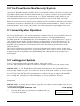
To Perform a Keypad and Siren Test
LCD Display
1.
From the Ready state press and enter the [Master code] to
access User Functions.
-5-
Press (*) for <>
User Functions
Chapter 3.0 The PowerSeries Neo Security System
2.
Press or use the scroll keys to navigate to System Test and press
[*]. The system activates all keypad sounders, bells/sirens and
keypad LEDs for two seconds.
3.
To go back to the Ready state press [*].
Press (*) for <>
System Test
3.3 Monitoring
This system is capable of transmitting alarms, troubles & emergency information to a central station. If you initiate an alarm by mistake, immediately call the central station to prevent an unnecessary response.
Note: For CP-01 systems, the monitoring function must be enabled by the installer before it
becomes functional. There is a communicator delay of 30 seconds in this control panel. It can be
removed, or it can be increased up to 45 seconds, at the option of the end-user by consulting with
the installer.
3.4 Maintenance
With normal use, the system requires minimum maintenance. Note the following points:
l
Do not wash the security equipment with a wet cloth. Light dusting with a slightly
moistened cloth should remove normal accumulations of dust.
l
Use the system test described in “Testing Your System” to check the battery condition.
We recommend, however, that the standby batteries be replaced every 3-5 years.
l
For other system devices such as smoke detectors, passive infrared, ultrasonic or
microwave motion detectors or glassbreak detectors, consult the manufacturer’s literature
for testing and maintenance instructions.
-6-
Chapter 4.0 Arming the System
4.0 Arming the System
The PowerSeries Neo system can be armed using a keypad, a 2-way wireless key or a proximity
tag. For more information on additional arming types, refer to the PowerSeries Neo User manual
(29008610R001).
4.1 Away Arming the System with the Keypad
Away mode activates the complete alarm system by:
l
Arming all perimeter sensors.
l
Arming all interior sensors.
To Arm the System in Away Mode
LCD Display
1.
Ensure all windows and doors are closed and that the Ready
indicator is on.
Date Time
JAN 02/13 2:06a
2.
To arm using the Away key
, press and hold the Away
key for 2 seconds and, if required, enter your [access code] or
present your proximity tag.
System is
Ready to Arm
then
OR
3.
To Quick Arm the system press [*][0].
Present Tag or
Enter Code
If zones have been bypassed, ICN or LED keypads bypass
* Warning *
Bypass Active
LED
will light and the bypassed zones #s will be shown.
On an LCD keypad a warning appears.
4.
After successfully initiating the arming sequence the:
l
l
l
l
l
Exit Delay in
Progress
Armed
indicator turns on.
Ready
indicator remains lit.
Exit Delay timer begins counting down.
Keypad beeps six times, continues beeping once per second
until beeping rapidly in the final ten seconds.
The system may be configured to have a persistent exit
delay that only ends when the exit door is opened and
closed, or when a button is pressed outside the protected
premises.
5.
To cancel the arming sequence, enter your [access code] or
present your proximity tag to the keypad reader.
System Disarmed
No Alarm Memory
6.
Once the exit delay timer expires, thereby arming the system,
the:
System Armed
in Away Mode
l
l
l
Ready indicator turns off.
Armed indicator remains on.
Keypad stops sounding.
Note: The installer configures the exit delay timer and whether or not an access code is required
for arming the system.
-7-
Chapter 4.0 Arming the System
4.2 Exit Delay Time Restart
The control panel provides an option where, if a entry/exit zone is tripped a second time prior to the
end of the exit delay, the exit delay time restarts. The exit delay timer can only be restarted once.
4.3 Alarm Cancel Window
The control panel provides a period of time in which the user can cancel the alarm transmission.
The minimum duration of this time is five minutes.
If the programmed alarm transmission delay has expired, canceling an alarm sends a message to the
monitoring station. Upon a successful transmission of the cancellation message the keypad will beep
6 times.
Note: Must be enabled and configured by installer.
Note: For CP-01 systems, alarm transmission delay must not exceed 45 seconds.
4.4 Using 2-way Wireless Keys and Proximity Tags
2-way wireless keys allow users in the close proximity of their house the ability to readily arm/disarm their system, and to call for help. For information on enrolling wireless keys see 7.1.3 "User
Labels (LCD keypads only)".
1
6
7
6
5
5
2
3
4
1
2
3
4
1.
2.
3.
4.
5.
6.
7.
Away Arm
Stay Arm
Disarm
Panic
Command Output 1
Message LED
Status LEDs
1.
2.
3.
4.
5.
6.
Away Arm
Stay Arm
Disarm
Panic
Command Output 1
LED
Note: Panic feature has not been evaluated by UL. All wireless key buttons are programmable.
Verify the functions assigned to each key with your installer. When using compatible wireless keys
there is one bell squawk for arming and two bell squawks for disarming.
4.4.1 Arming the system with a 2-way wireless key
If configured, the PowerSeries Neo system can be armed using the following wireless keys:
l
PG4929/PG8929/PG9929
l
PG4939/PG8939/PG9939
To Arm the System with a 2-way wireless key
l
Press the desired Arming mode button anytime the system Ready indicator is on.
4.4.2 Arming the System with a Proximity Tag
If configured, the PowerSeries Neo system can be armed using MPT proximity tags.
-8-
Chapter 4.0 Arming the System
To Arm the System with a Proximity tag
l
Present your Proximity tag to a keypad equipped with a proximity sensor anytime the system Ready indicator is on.
l
If configured by your installer, enter your access code.
4.5 Disarming the System
Depending on your system configuration, there are multiple methods you can use to disarm your system. You can disarm the system using a:
l
Keypad
l
2-way wireless key
l
Proximity Tag
To Disarm the System with a Keypad
1.
Enter your [access code] or present your proximity tag anytime the system is armed.
(Armed
2.
indicator is on).
If you walk through the entry door the keypad will beep. Disarm within _____ seconds to
avoid an alarm condition.
To Disarm the System with a 2-way Wireless Key
1.
Press the disarm button anytime the system is armed. (Armed
indicator is on).
2.
If you walk through the entry door the keypad will beep. Press the disarm button within ____
_ seconds to avoid an alarm condition.
Note: After disarming a system with an HS2LCD keypad using a 2-way wireless key, always
check the alarm memory to determine if any alarms have occurred during the armed period.
To Disarm the System with a Proximity Tag
1.
Present your Proximity Tag to a keypad equipped with a proximity sensor anytime the system is armed. (Armed indicator is on) and if configured as required, enter your access code.
2.
If you walk through the entry door the keypad will beep. Present your Proximity Tag within
_____ seconds to avoid an alarm condition.
Note: Duration of Entry timer is programmed by installer.
4.5.1 Disarming Error
If your code is invalid, the system will not disarm and a 2-second error tone will sound. If this
occurs, press [#] and re-enter your access code.
-9-
Chapter 5.0 Emergency Keys
5.0 Emergency Keys
IMPORTANT: EMERGENCY USE ONLY!
Pressing both the emergency keys generates a Fire, Medical, or Panic Alarm, and alerts the monitoring station. e.g., to generate a medical alarm press both of the medical alarm keys for 2 seconds
and the display on an LCD keypad will show Hold down keys for Med. Alarm.The keypad beeps to
indicate that the alarm input has been accepted and sent to the monitoring station.
Fire Alarm
Medical Alarm
Panic Alarm
Note: Verify with your alarm company that your system is equipped with emergency keys.
Note: Fire keys can be disabled by the installer.
Note: Having an optional audio verification module installed in your system allows the monitoring
station to open 2-way communication when notified of an alarm.
- 10 -
Chapter 6.0 Access Code Types
6.0 Access Code Types
The alarm system provides the following user access code types:
Code
Add User Delete
User
Arm Disarm Access
Codes
User Functions
Installer
Master
All
All
Yes Yes
Yes
Yes
No
User
No
No
Yes Yes
No
No
No
Supervisor
All but
Master
All but
Master
Yes Yes
Yes
Yes
No
Duress
No
No
Yes Yes
No
No
No
One-time No
No
Yes 1/day
No
No
No
user
Installer and Master code are system codes that can be changed but not deleted. The other codes are
user-defined and can be added or deleted as necessary. By default, access codes have the same partition and attribute programming as the code used to program them.
Note: When using 6-digit access codes, the minimum number of access code variations is 10526 per
user. Additionally, there are no disallowed codes.
Master
Code
By default the master code can access all partitions and can perform any keypad
function. This code can be used to program all access codes, including the supervisor and duress codes. The master code is code # [01].
User
Codes
This type of access code is used to arm and disarm assigned partitions and can
access the User Functions menu.
Supervisor Use when you want to allow additional users to manage Access Codes [*5] or User
Functions[*6]. Supervisor codes created by the master code will have the same
Codes
attributes as the master code. Supervisor codes created by another supervisor code
will have the same attributes, except the supervisor attribute. Must be assigned
manually afterward. After creation, attributes can be changed for all supervisor
codes. For information on how to program a supervisor code see 7.2 "Configuring
additional User Options".
Duress
Codes
Use if forced to access your keypad under threat. Duress codes function the same
as user access codes, except they transmit a Duress Report to your monitoring station when used to perform any function on the system.
Duress codes cannot be used to access Access Codes[*5], User Functions[*6] or
Installer[*8] menus. For information on how to program a Duress Code see 7.2
"Configuring additional User Options".
One Time Use when needing to grant someone one time access to your home once per day,
User Code i.e., a cleaning person or contractor. The ability to disarm the system is reset at
midnight or when the one time user code is keyed in by the master code user. For
information on how to program a One Time User Code see 7.2 "Configuring additional User Options".
To open the Access Codes Menu
LCD Display
- 11 -
Chapter 6.0 Access Code Types
1.
Press [*][5]
Press (*) for <>
Access Codes
OR
press [*] and use the scroll keys to navigate to Access Codes
and press [*].
2.
Enter [Master or supervisor code].
Present Tag or
Enter Code
3.
Enter [2 digit user #]
Press (*) for <>
{User Label}
OR
scroll through the list of users and press [*]. On an LED
keypad the user number will begin flashing.
4.
To go back to the Ready state press [#].
6.1 Adding, Changing and Deleting Access Codes
Each configured user is assigned a number from 01-95. Access codes cannot be duplicated.
To Add or Change User Access Codes
LCD Display
1.
From the desired user press [*] or [1].
Press (*) for <>
Access Code
2.
Enter a new 4 or 6 digit access code. After entering a new
code you will be automatically returned to the previous menu,
and on an LCD display the flag is changed to P from -. On an
ICN or LED keypad the programmed user will have their
digits displayed. If a duplicate code is entered the error tone
will sound.
Enter New Code
XXXXXX
To Delete a User Access Code
then
Press (*) for <>
User Code 03 P
LCD Display
1.
From the desired user press [*] or [1].
Press (*) for <>
Access Code
2.
Press [*]. The code is deleted, and you are returned to the previous screen. The flag is changed to - from P. On an ICN or
LED keypad the programmed user’s digits will cease being displayed.
Enter New Code
030516
then
(*) to Edit <>
User Code 03 -
Note: Any proximity tags associated with deleted user codes will need to be re-enrolled.
6.2 Burglary Verification
The Control Panel includes cross zone and sequential detection features that require a trip on two or
more zones within a given time period, to generate a confirmed alarm and immediate police
response.
Note: Must be enabled and configured by installer.
6.3 Swinger Shutdown
The Control Panel has a swinger shutdown feature that when enabled a programmable number of
trips shall shut down the zone. All burglary zone types have this feature enabled in CP-01 installations.
- 12 -
Chapter 6.0 Access Code Types
Note: Must be enabled and configured by installer.
6.4 Call Waiting
The Control Panel includes a programmable option for call waiting to prevent a call waiting line
from interfering with the alarm verification process. This option is disabled by default.
Note: Must be enabled and configured by installer.
6.5 Fire Alarm Verification
Fire Alarm Verification is an available option for Fire zones. If configured, once the conditions for
alarm verification are met the fire alarm will sound and an alarm transmission will be sent to the
monitoring station.
Note: Must be enabled and configured by installer.
6.6 System Lockout due to Invalid Attempts
If too many invalid access codes are entered, your system can be configured to automatically lock
out inputs from all keypads, wireless and proximity keys, and SMS commands for a specified duration. When any keys are pressed, an error tone will sound. FMP keys are still active during
Keypad Lockout.
Note: Feature and lockout duration must be configured by installer.
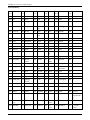
6.7 User Labels (LCD keypads only)
Adding or editing labels is done by using a pre-programmed word library. The following table library lists the full library and the associated three digit code.
To edit a user label
LCD Display
1.
From the applicable user, press [3] or use the scroll keys to
scroll to User Labels and press [*].
Press (*) for <>
User Labels
2.
Press [*] [*] to enter word library.
Program Name
{User 1 Label 1}
3.
Use the scroll keys to scroll through the list of words or
use the [3-digit number] to display the desired word.
Press [*] to select the word.
4.
To enter an additional word, repeat step 3.
Press (*) for <>
{User Label}
- 13 -
Chapter 6.0 Access Code Types
Word Library
Ite- Text
m#
Ite- Text
m#
Ite- Text
m#
Ite- Text
m#
Ite- Text
m#
Ite- Text
m#
001 Aborted
042 Control
083 Garage
124 Motion
165 Shop
206 E
002 AC
043 Date
084 Gas
125 No
166 Side
207 F
003 Access
044 Daughter’- 085 Glass
s
126 North
167 Siren
208 G
004 Active
045 Degrees
086 Goodbye
127 Not
168 Sliding
209 H
005 Activity
046 Delay
087 Gym
128 Now
169 Smoke
210 I
006 Alarm
047 Den
088 Hallway
129 Number 170 Son’s
211 J
007 All
048 Desk
089 Heat
130 Off
171 Sound
212 K
008 AM
049 Detector
090 Hello
131 Office
172 South
213 L
009 Area
050 Dining
091 Help
132 OK
173 Special
214 M
010 Arm
051 Disarmed 092 High
133 On
174 Stairs
215 N
011 Armed
052 Door
093 Home
134 Open
175 Stay
216 O
012 Arming
053 Down
094 House
135 Opening
176 Sun
217 P
013 Attic
054 Download 095 In
136 Panic
177 Supervisory 218 Q
014 Auxiliary 055 Downstairs
096 Install
137 Partition
178 System
219 R
015 Away
056 Drawer
097 Interior 138 Patio
179 Tamper
220 S
016 Baby
057 Driveway 098 Intrusion
139 Pet
180 Temperature
221 T
017 Back
058 Duct
099 Invalid
140 Phone
181 Test
222 U
018 Bar
059 Duress
100 Is
141 Please
182 Time
223 V
019 Basement 060 East
101 Key
142 PM
183 To
224 W
020 Bathroom 061 Energy
Saver
102 Kids
143 Police
184 Touchpad
225 X
021 Battery
062 Enter
103 Kitchen 144 Pool
185 Trouble
226 Y
022 Bedroom
063 Entry
104 Latchkey
186 Unbypass
227 Z
023 Bonus
064 Error
105 Laundry 146 Power
187 Unit
228 (Space)
024 Bottom
065 Exercise
106 Left
147 Press
188 Up
229 ’
(Apostrophe)
025 Breezeway
066 Exit
107 Level
148 Program
189 West
230 - (Dash)
026 Building
067 Exterior
108 Library 149 Progress
190 Window
231 _ (Underscore)
145 Porch
- 14 -
Chapter 6.0 Access Code Types
027 Bus
068 Factory
109 Light
150 Quiet
191 Zone
232 *
028 Bypass
069 Failure
110 Lights
151 Rear
192 0
233 #
029 Bypassed 070 Family
111 Living
152 Receive- 193 1
r
234 :
030 Enclosure 071 Father’s
112 Load
153 Report
194 2
235 /
031 Canceled 072 Feature
113 Loading 154 RF
195 3
236 ?
- 15 -
Chapter 7.0 Trouble Conditions
7.0 Trouble Conditions
Trouble Conditions (Level 1) are comprised of various trouble types (Level 2) which may in turn be
related to a specific zone, module, device or additional type of system equipment (Level 3). For an
explanation of possible trouble conditions and the recommended actions required see Table 9-1.
When the system detects a trouble condition the following occurs:
l
The Trouble indicator turns on.
l
The keypad beeps once every 10 seconds.
l
Press the [*] key to silence the keypad beeps.
Examining troubles is done by pressing [*][2]. When viewing troubles, the trouble indicator flashes
to identify the level of trouble being viewed. One flash = level 1, two flashes = level 2 etc.
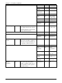
Trouble Conditions
Trouble Condi- Trouble Description
Trouble Trouble Trouble tion
#
Types
#
Notification
Level 1
Level 2 Level 3
Note: Trouble #s are used to identify the number to view the trouble and depending on the keypad
type being used, identifies which LED or digit illuminates to display the trouble. Similarly,
Trouble Notification identifies the range that may be displayed on the keypad. When exploring the
trouble levels, the Trouble indicator will flash to identify which level you are currently viewing.
Service
Required
01
Battery Trouble 02
01
02
Auxiliary Sup- 03
ply
Time and
Date
04
Output 1 Fault 05
Assorted Trouble types.
Bell Circuit
Time and Date troubles can be
resolved by resetting the
Time/Date. To set Time/Date
press [*][6][0][1]. For all
other troubles call for service.
RF Jam
The system has detected a bat- Low Battery
tery trouble condition. Call for (System
service.
Label)
- 16 -
01
n/a
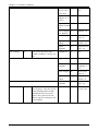
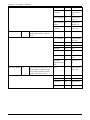
Chapter 7.0 Trouble Conditions
Bus Voltage
03
04
02
High Current
Output Low
Battery
04
Module 1-4
High Current 05
Output No Battery
Module 1-4
Power Supply 07
Low Battery
Module 1-4
Power Supply 05
Power supply 1-4
High Current
Output
06
Output terminal 1-4
Output
Expander
08
Output module 1-16
01
n/a
Keypad
02
Keypad 1-16
Zone
Expander
04
Zone
expander 115
Power Supply 05
Power supply 1-4
High Current
Output
06
Output terminal 1-4
Output
Expander
08
Output module 1-16
01
Zone label
or 001-128
The system has detected a
HSM2HOST
trouble condition. Call for service.
AC Troubles
No Battery
service (System Label)
The system is experiencing
Zone
loss of power. Call for service.
If the building and/or neighborhood has lost electrical
power, the system will continue to operate on battery for
several hours.
- 17 -
n/a
Chapter 7.0 Trouble Conditions
Siren
03
Siren 1-16
Repeater
04
Repeater 18
Power Supply 05
Power supply 1-4
High Current
Output
Output terminal 1-4
06
System Label 07
Device Faults
05
The system has detected an
issue with one or more connected devices. Call for service.
Device Battery 06
Device
Tampers
07
Gas
Heat
CO
Freeze
Probe Disconnected
Fire
Zone
01
Zone label
or 001-128
Keypad
02
Keypad 1-16
Siren
03
Siren 1-16
Repeater
04
Repeater 18
01
Zone label
or 001-128
Keypad
02
Keypad 1-16
Siren
03
Siren 1-16
Repeater
04
Repeater 18
User
05
Wireless
key 1-32
Gas
The system has detected an
Zone
issue with one or more of the
device batteries. For Zone,
Keypad and Wireless Key battery troubles see the accompanying documentation for how
to change the batteries. For all
other troubles call for service.
The system has detected a
tamper condition with one or
more devices on the system.
Call for service.
- 18 -
n/a
Chapter 7.0 Trouble Conditions
RF Delinquency 08
Heat
CO
Freeze
Probe Disconnected
Fire
Zone
01
Zone label
or 001-128
Keypad
02
Keypad 1-16
Siren
03
Siren 1-16
Repeater
04
Repeater 18
01
Zone label
or 001-128
The system has detected wire- Zones
less signal interference that is
causing improper system operation. Call for service.
Keypad
02
Keypad 1-16
Siren
03
Siren 1-16
Repeater
04
Repeater 18
HSM2HOST
01
n/a
Keypad
02
Keypad 1-16
Zone
Expander
04
Zone
Expander 115
Module Supervision
09
The system has detected a
supervisory trouble condition
with one or more modules on
the system. Call for service.
Module
Tampers
10
The system has detected a
tamper condition with one or
more modules on the system.
Call for service.
- 19 -
Power Supply 05
Power supply 1-4
High Current
Output
06
Output terminal 1-4
Output
Expander
08
Output module 1-16
HSM2HOST
01
n/a
Chapter 7.0 Trouble Conditions
Communications 11
02
Keypad 1-16
Zone
Expander
04
Zone
Expander 115
Power Supply 05
Power supply 1-4
High Current
Output
06
Output terminal 1-4
Output
Expander
08
Output module 1-16
The system has detected a com- TLM Trouble 01
munication trouble. Call for
service.
Not Networked 12
Keypad
FTC Trouble
02
Phone Number 1-4
SIM Lock
03
n/a
Cellular
04
n/a
Ethernet
05
n/a
Receiver
06
Receiver 14
Supervision
07
Supervision
1-4
Alternate
10
Communicator
FTC
Receiver 14
The system has detected a net- Zone
work trouble condition with
one or more modules on the
system. Call for service.
- 20 -
n/a
01
Zone label
001-128
Keypad
02
Keypad 1-16
Siren
03
Siren 1-16
Repeater
04
Repeater 18
User
05
Users 01-95
Chapter 8.0 Safety Instructions
8.0 Safety Instructions
WARNING! This equipment has no mains on/off switch. the plug of the direct plug-in power supply is intended to serve as the disconnecting device if the equipment must be quickly disconnected. it
is imperative that access to the mains plug and associated mains socket/outlet, is never obstructed.
WARNING! When using equipment connected to the mains and/or to the telecommunication network, there are basic safety instructions that should always be followed. Refer to the safety instructions provided with this product and save them for future reference.To reduce the risk of fire,
electric shock and/or injury, observe the following:
l
Do not attempt to service this product yourself. Opening or removing the cover may
expose you to dangerous voltage or other risk. Refer servicing to qualified service persons.
Never open the device yourself.
l
Any servicing shall be referred to Service Persons only.
l
Dispose the used batteries according to the local rules and regulations.
l
Do not leave and/or deposit any object on the top of the equipment cabinet. The cabinet, as
installed, is not designed to support any supplementary weight.
l
Do not spill any liquids on the cabinet.
l
Do not touch the equipment and its connected cables during an electrical storm; there may
be a risk of electric shock.
l
Never touch uninsulated wires or terminals unless the Direct Plug In transformer has been
disconnected.
l
Ensure that cables are positioned so that accidents cannot occur. Connected cables must
not be subject to excessive mechanical strain.Do not spill any type of liquid on the equipment.
l
Do not use the Alarm system to report a gas leak if the system is near a leak.
l
The equipment is stationary/fixed and direct plug-in connected to the mains and shall be
installed and serviced by service persons only.
8.1 Regular Maintenance and Troubleshooting
Keep your Alarm Controller in optimal condition by following all the instructions that are included
within this manual and/or marked on the product.
8.1.1 Cleaning
l
l
l
l
Clean the units by wiping with a damp cloth only.
Do not use abrasives, thinners, solvents or aerosol cleaners (spray polish) that may enter
through holes in the Alarm Controller and cause damage.
Do not use any water or any other liquid.
Do not wipe the front cover with alcohol.
8.1.2 Troubleshooting
Occasionally, you may have a problem with your Alarm Controller or telephone line. If this happens, your Alarm Controller will identify the problem and displays an error message. Refer to the
provided list when you see an error message on the display. If additional help is required, contact
your distributor for service.
Note: There are no parts replaceable by the end-user within this equipment, except for the keypad
batteries. Dispose of used batteries as per local rules and regulations.
This publication covers the following models x = 9 (912-919MHz UL/ULC systems) 4 (433MHz) or
8 (868MHz).
- 21 -
Chapter 8.0 Reference Sheets
l
HS2016
l
HS2LCD
l
HS2LCDWFx
l
HS2ICN
l
HS2128
l
HS2LCDP
l
HS2LCDWFPx
l
HS2ICNP
l
HS2032
l
HS2LCDRFx
l
HS2LCDWFPVx
l
HS2ICNRFx
l
HS2064
l
HS2LCDRFPx
l
HS2LED
l
HS2ICNRFPx
The following is a list of warnings applicable when this equipment is connected to the New Zealand
Telecom Network.
GENERAL WARNING
The following is a list of warnings applicable when this equipment is connected to the New Zealand
Telecom Network.
The grant of a Telepermit for any item of terminal equipment indicates only that Telecom has
accepted that the item complies with minimum conditions for connection to its network. It indicates
no endorsement of the product by Telecom, nor does it provide any sort of warranty. Above all, it
provides no assurance that any item will work correctly in all respects with another item of Telepermitted equipment of a different make or model, nor does it imply that any product is compatible
with all of Telecom's network services.
Reverse Numbering (Decadic Signalling)
Decadic signaling should not be used as it is being progressively phased out of the network. DTMF
dialling is 100% available and it should always be used.
Line Grabbing Equipment
This equipment is set up to carry out test calls at pre-determined times. Such test calls will interrupt
any other calls that may be set up on the line at the same time. The timing set for such test calls
should be discussed with the installer. The timing set for test calls from this equipment may be subject to 'drift'. If this proves to be inconvenient and your calls are interrupted, then the problem of
timing should be discussed with the equipment installer. The matter should NOT be reported as a
fault to Telecom Faults Service.
D.C. Line Feed To Other Devices
During dialing, this device unit does not provide DC voltage to the series port connection and this
may cause loss of memory functions for the terminal devices (local telephone) connected to T-1, R1.
General Operation (ringer sensitivity and loading)
This device only responds to Distinctive Alert cadences DA1 and DA2.
In the event of any problem with this device, it is to be disconnected. A CPE item connected to one
of the device’s terminal ports may be connected directly in its place. The user should then arrange
for the product to be repaired. Should the matter be reported to Telecom as a wiring fault, and the
fault is proven to be due to this product, a call-out charge will be incurred.
8.0 Reference Sheets
Fill out the following information for future reference and store this guide in a safe place.
8.2 System Information
Mark if Buttons are Enabled
o [F] FIRE o [M] Medical o [P] PANIC
The Exit Delay Time is _______ seconds.
- 22 -
Chapter 8.0 Regular Maintenance and Troubleshooting
The Entry Delay Time is _______ seconds.
8.3 Service Contact Information
Central Station Information
Account #: ___________________ Telephone #: __________________
Installer Information:
Company: ___________________ Telephone #: __________________
Battery Installation / Service Date:
_____________________
_____________________
_____________________
IMPORTANT: If you suspect a false alarm signal has been sent to the central monitoring station,
call the station to avoid an unnecessary response.
8.0 Regular Maintenance and Troubleshooting
Keep your Alarm Controller in optimal condition by following all the instructions that are included
within this manual and/or marked on the product. Change the batteries every 3-5 years.
8.4 Cleaning
Clean the units by wiping with a damp cloth only.
Do not use abrasives, thinners, solvents or aerosol cleaners (spray polish) that may enter
through holes in the Alarm Controller and cause damage.
Do not use any water or any other liquid.
Do not wipe the front cover with alcohol.
l
l
l
l
8.5 Access Code and Sensor/Zone information
Master Code [01] : _________________________
Access Code Reference Sheet
Code Access Code Code Access Code Code Access Code Code Access Code
01
13
25
37
02
14
26
38
03
15
27
39
04
16
28
40
05
17
29
41
06
18
30
42
07
19
31
43
08
20
32
44
09
21
33
45
10
22
34
46
11
23
35
47
12
24
36
48
- 23 -
Chapter 8.0 Regular Maintenance and Troubleshooting
49
55
61
67
50
56
62
68
51
57
63
69
52
58
64
70
53
59
65
71
54
60
66
72
73
79
85
91
74
80
86
92
75
81
87
93
76
82
88
94
77
83
89
95
78
84
90
Sensor/Zone Information
Sensor Protected Area
Sensor Type
Sensor Protected Area
Sensor Type
01
65
02
66
03
67
04
68
05
69
06
70
07
71
08
72
09
73
10
74
11
75
12
76
13
77
14
78
15
79
16
80
17
81
18
82
19
83
20
84
21
85
22
86
23
87
24
88
- 24 -
Chapter 8.0 Regular Maintenance and Troubleshooting
Sensor Protected Area
Sensor Type
Sensor Protected Area
Sensor Type
25
89
26
90
27
91
28
92
29
93
30
94
31
95
32
96
33
97
34
98
35
99
36
100
37
101
38
102
39
103
40
104
41
105
42
106
43
107
44
108
45
109
46
110
47
111
48
112
49
113
50
114
51
115
52
116
53
117
54
118
55
119
56
120
57
121
58
122
59
123
60
124
61
125
- 25 -
Chapter 8.0 Regular Maintenance and Troubleshooting
Sensor Protected Area
Sensor Type
Sensor Protected Area
Sensor Type
62
126
63
127
64
128
8.6 Locating Detectors and Escape Plan
Locating Detectors and Escape Plan
The following information is for general guidance only and it is recommended that local fire codes
and regulations be consulted when locating and installing smoke and CO alarms.
8.6.1 Smoke Detectors
Research has shown that all hostile fires in homes generate smoke to a greater or lesser extent.
Experiments with typical fires in homes indicate that detectable quantities of smoke precede detectable levels of heat in most cases. For these reasons, smoke alarms should be installed outside of
each sleeping area and on each storey of the home.
The following information is for general guidance only and it is recommended that local fire codes
and regulations be consulted when locating and installing smoke alarms.
It is recommended that additional smoke alarms beyond those required for minimum protection be
installed. Additional areas that should be protected include: the basement; bedrooms, especially
where smokers sleep; dining rooms; furnace and utility rooms; and any hallways not protected by
the required units. On smooth ceilings, detectors may be spaced 9.1m (30 feet) apart as a guide.
Other spacing may be required depending on ceiling height, air movement, the presence of joists,
uninsulated ceilings, etc. Consult National Fire Alarm Code NFPA 72, CAN/ULC-S553-02 or other
appropriate national standards for installation recommendations.
l
Do not locate smoke detectors at the top of peaked or gabled ceilings; the dead air space in
these locations may prevent the unit from detecting smoke.
l
Avoid areas with turbulent air flow, such as near doors, fans or windows. Rapid air movement around the detector may prevent smoke from entering the unit.
l
Do not locate detectors in areas of high humidity.
l
Do not locate detectors in areas where the temperature rises above 38ºC (100ºF) or falls
below 5ºC (41ºF).
l
Smoke detectors should always be installed in USA in accordance with Chapter 11 of
NFPA 72, the National Fire Alarm Code: 11.5.1.1.
Where required by applicable laws, codes, or standards for a specific type of occupancy, approved
single- and multiple-station smoke alarms shall be installed as follows:
1.
In all sleeping rooms and guest rooms.
2.
Outside of each separate dwelling unit sleeping area, within 6.4 m (21 ft) of any door to a
sleeping room, the distance measured along a path of travel.
3.
On every level of a dwelling unit, including basements.
4.
On every level of a residential board and care occupancy (small facility), including basements
and excluding crawl spaces and unfinished attics.
5.
In the living area(s) of a guest suite.
6.
In the living area(s) of a residential board and care occupancy (small facility).
- 26 -
Chapter 8.0 Regular Maintenance and Troubleshooting
Figure 1
Figure 2
Figure 3
Figure 3a
Figure 4
8.6.2 Fire Escape Planning
There is often very little time between the detection of a fire and the time it becomes deadly. It is
thus very important that a family escape plan be developed and rehearsed.
1.
Every family member should participate in developing the escape plan.
2.
Study the possible escape routes from each location within the house. Since many fires occur
at night, special attention should be given to the escape routes from sleeping quarters.
3.
Escape from a bedroom must be possible without opening the interior door.
Consider the following when making your escape plans:
l
Make sure that all border doors and windows are easily opened. Ensure that they are not
painted shut, and that their locking mechanisms operate smoothly.
l
If opening or using the exit is too difficult for children, the elderly or handicapped, plans
for rescue should be developed. This includes making sure that those who are to perform
the rescue can promptly hear the fire warning signal.
l
If the exit is above the ground level, an approved fire ladder or rope should be provided as
well as training in its use.
l
Exits on the ground level should be kept clear. Be sure to remove snow from exterior patio
doors in winter; outdoor furniture or equipment should not block exits.
l
Each person should know the predetermined assembly point where everyone can be accounted for (e.g., across the street or at a neighbor's house). Once everyone is out of the building, call the fire department.
l
A good plan emphasizes quick escape. Do not investigate or attempt to fight the fire, and
do not gather belongings as this can waste valuable time. Once outside, do not re-enter the
house. Wait for the fire department.
- 27 -
Chapter 8.0 Regular Maintenance and Troubleshooting
Write the fire escape plan down and rehearse it frequently so that should an emergency
arise, everyone will know what to do. Revise the plan as conditions change, such as the
number of people in the home, or if there are changes to the building’s construction.
l
Make sure your fire warning system is operational by conducting weekly tests. If you are
unsure about system operation, contact your installer.
We recommend that you contact your local fire department and request further information on fire
safety and escape planning. If available, have your local fire prevention officer conduct an in-house
fire safety inspection.
l
Figure 5
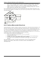
8.6.3 Carbon Monoxide Detectors
Carbon monoxide is colorless, odorless, tasteless, and very toxic, it also moves freely in the air. CO
detectors can measure the concentration and sound a loud alarm before a potentially harmful level
is reached. The human body is most vulnerable to the effects of CO gas during sleeping hours; therefore, CO detectors should be located in or as near as possible to sleeping areas of the home. For
maximum protection, a CO alarm should be located outside primary sleeping areas or on each level
of your home. Figure 5 indicates the suggested locations in the home.
Do NOT place the CO alarm in the following areas:
l
Where the temperature may drop below -10ºC or exceed 40ºC
l
Near paint thinner fumes
l
Within 5 feet (1.5m) of open flame appliances such as furnaces, stoves and fireplaces
l
In exhaust streams from gas engines, vents, flues or chimneys
l
Do not place in close proximity to an automobile exhaust pipe; this will damage the
detector
PLEASE REFER TO THE CO DETECTOR INSTALLATION AND OPERATING
INSTRUCTION SHEET FOR SAFETY INSTRUCTIONS AND EMERGENCY
INFORMATION.
- 28 -
Chapter 9.0 Regulatory Agency Statements
9.0 Regulatory Agency
Statements
FCC COMPLIANCE STATEMENT
CAUTION: Changes or modifications not expressly approved by Digital Security
Controls could void your authority to use this equipment.
This equipment has been tested and found to comply with the limits for a Class B
digital device, pursuant to Part 15 of the FCC Rules. These limits are designed to
provide reasonable protection against harmful interference in a residential installation. This equipment generates, uses and can radiate radio frequency energy and,
if not installed and used in accordance with the instructions, may cause harmful
interference to radio communications. However, there is no guarantee that interference will not occur in a particular installation. If this equipment does cause
harmful interference to radio or television reception, which can be deter-mined by
turning the equipment off and on, the user is encouraged to try to correct the interference by one or more of the following measures:
- Re-orient the receiving antenna.
- Increase the separation between the equipment and receiver.
- Connect the equipment into an outlet on a circuit different from that to which
the receiver is connected.
- Consult the dealer or experienced radio/television technician for help.
The user may find the following booklet prepared by the FCC useful: “How to
Identify and Resolve Radio/Television Interference Problems”. This booklet is
available from the U.S. Government Printing Office, Washington D.C. 20402, Stock
# 004-000-00345-4.
The keypads represented in this manual can be used with the following Control
Units: HS2016, HS2032, HS2064, HS2128.
IMPORTANT INFORMATION
This equipment complies with Part 68 of the FCC Rules and, if the product was
approved July 23, 2001 or later, the requirements adopted by the ACTA. On the
side of this equipment is a label that contains, among other information, a product
identifier. If requested, this number must be provided to the Telephone Company.
HS2016 Product Identifier US:F53AL01BHS2128
HS2032 Product Identifier US:F53AL01BHS2128
HS2064 Product Identifier US:F53AL01BHS2128
HS2128 Product Identifier US:F53AL01BHS2128
USOC Jack: RJ-31X
Telephone Connection Requirements
A plug and jack used to connect this equipment to the premises wiring and telephone network must comply with the applicable FCC Part 68 rules and requirements adopted by the ACTA. A compliant telephone cord and modular plug is
provided with this product. It is designed to be connected to a compatible modular
jack that is also compliant. See installation instructions for details.
Ringer Equivalence Number (REN)
The REN is used to determine the number of devices that may be connected to a
telephone line. Excessive RENs on a telephone line may result in the devices not
ringing in response to an incoming call. In most but not all areas, the sum of RENs
should not exceed five (5.0). To be certain of the number of devices that may be
connected to a line, as determined by the total RENs, contact the local Telephone
Company. For products approved after July 23, 2001, the REN for this product is
part of the product identifier that has the format US: AAAEQ##TXXXX. The digits
represented by ## are the REN without a decimal point (e.g., 03 is a REN of 0.3).
For earlier products, the REN is separately shown on the label.
Incidence of Harm
If this equipment (HS2016, HS2032, HS2064, HS2128) causes harm to the telephone
network, the telephone company will notify you in advance that temporary discontinuance of service may be required. But if advance notice is not practical, the
Telephone Company will notify the customer as soon as possible. Also, you will be
advised of your right to file a complaint with the FCC if you believe it is necessary.
Changes in Telephone Company Equipment or Facilities
The Telephone Company may make changes in its facilities, equipment, operations or procedures that could affect the operation of the equipment. If this happens the Telephone Company will provide advance notice in order for you to
make necessary modifications to maintain uninterrupted service.
Equipment Maintenance Facility
If trouble is experienced with this equipment (HS2016, HS2032, HS2064, HS2128)
for repair or warranty information, contact the facility indicated below. If-the
equipment is causing harm to the telephone network, the Telephone Company
may request that you disconnect the equipment until the problem is solved. This
equipment is of a type that is not intended to be repaired by the end user.
DSC c/o APL Logistics 757 Douglas Hill Rd, Lithia Springs, GA 30122
Additional Information
Connection to party line service is subject to state tariffs. Contact the state public
utility commission, public service commission or corporation commission for
information.
Alarm dialing equipment must be able to seize the telephone line and place a
call in an emergency situation. It must be able to do this even if other equipment
(telephone, answering system, computer modem, etc.) already has the telephone
line in use. To do so, alarm dialing equipment must be connected to a properly
installed RJ-31X jack that is electrically in series with and ahead of all other
equipment attached to the same telephone line. Proper installation is depicted in
the figure below. If you have any questions concerning these instructions, you
should consult your telephone company or a qualified installer about installing the
RJ-31X jack and alarm dialing equipment for you.
INDUSTRY CANADA STATEMENT
NOTICE: The models: HS2016, HS2032, HS2064, HS2128 meet the applicable
Industry Canada Terminal Equipment Technical Specifications. This is confirmed
by the registration number. The abbreviation, IC, before the registration number
signifies that registration was performed based on a Declaration of Conformity
indicating that Industry Canada technical specifications were met. It does not
imply that Industry Canada approved the equipment.
NOTICE: The Ringer Equivalence Number (REN) for this terminal equipment is
0.1. The REN assigned to each terminal equipment provides an indication of the
maximum number of terminals allowed to be connected to a telephone interface.
The termination on an interface may consist of any combination of devices subject only to the requirement that the sum of the Ringer Equivalence Numbers of
all devices does not exceed 5.
HS2016 Registration number IC:160A-HS2128
HS2032 Registration number IC:160A-HS2128
HS2064 Registration number IC:160A-HS2128
HS2128 Registration number IC:160A-HS2128
This product is in conformity with EMC Directive 2004/108/EC based on results
using harmonized standards in accordance with article 10(5), R&TTE Directive
1999/5/EC based on following Annex III of the directive and LVD Directive
2006/95/EC based on results using harmonized standards.
This product meets the requirements of Class II, Grade 2 equipment as per EN
50131-1:2006 + A1:2009 Standard. This product is suitable for use in systems with
the following notification options:
- A (use of two warning devices and internal dialer required),
- B (self powered warning device and internal dialer required),
- C (internal dialer and alternate IP/3G communicator required)
- D (use of alternate IP/GSM communicator with encryption enabled required).
The Model HS2016, HS2032, HS2064, HS2128
Control Panel has been certified by Telefication according to EN50131-1:2006 +
A1:2009, EN50131-3:2009, EN50131-6:2008 and EN50136-1:1997 for Grade 2, Class
II, ATS2.
FCC AND INDUSTRY CANADA STATEMENTS FOR WIRELESS KEYPADS
Models: HS2LCDRF9, HS2LCDRFP9, HS2ICNRF9, HS2ICNRFP9 (operating in 912919MHz band) are compliant with applicable FCC Part 15.247 and IC RSS-210
rules.
WARNING! To comply with FCC and IC RF exposure compliance requirements,
the HS2LCDRF(P)9 or HS2ICNRF(P)9 keypads should be located at a distance of at
least 20 cm from all persons during
normal operation. The antennas used for this product must not be co-located or
operated in conjunction with any other antenna or transmitter.
This device complies with FCC Rules Part 15 and with Industry Canada licenseexempt RSS standard(s). Operation is subject to the following two conditions: (1)
This device may not cause harmful interference, and (2)this device must accept
any interference that may be received or that may cause undesired operation.
IC:160A – HS2KRFP9
The term “IC” before the radio certification number only signifies that Industry
Canada technical specifications were met.
AVERTISSEMENT! Pour répondre aux exigences de conformité
de la FCC et d’Industrie Canada sur les limites d'exposition aux radiofréquences
(RF), les pavés numériques HS2LCDRF(P)9 ou HS2ICNRF(P)9 doivent être installés
à une distance minimale de 20 cm de toute personne lors de leur fonctionnement
usuel. Ces derniers ne doivent pas être situés au même endroit, ni être en fonction
avec une autre antenne ou un autre transmetteur.
Le present appareil est conforme aux CNR d'Industrie Canada applicables aux
appareils radio exempts de licence. L'exploitation est autorisee aux deux conditions suivantes:
(1)l'appareil ne doit pas produire de brouillage, et (2) l'utilisateur de l'appareil
doit accepter tout brouillage radioelectrique subi, meme si le brouillage est susceptible d'en compromettre le fonctionnement.
GENERAL WARNING
The following is a list of warnings applicable when this equipment is connected to
the New Zealand Telecom Network.
The grant of a Telepermit for any item of terminal equipment indicates only that
Telecom has accepted that the item complies with minimum conditions for connection to its network. It indicates no endorsement of the product by Telecom, nor
does it provide any sort of warranty. Above all, it provides no assurance that any
item will work correctly in all respects with another item of Telepermitted equipment of a different make or model, nor does it imply that any product is compatible with all of Telecom's network services.
- 29 -
Chapter 9.0 Regulatory Agency Statements
REVERSE NUMBERING (DECADIC SIGNALLING)
Decadic signaling should not be used as it is being progressively phased out of the
network. DTMF dialling is 100% available and it should always be used.
LINE GRABBING EQUIPMENT
This equipment is set up to carry out test calls at pre-determined times. Such test
calls will interrupt any other calls that may be set up on the line at the same
time. The timing set for such test calls should be discussed with the installer. The
timing set for test calls from this equipment may be subject to 'drift'. If this proves
to be inconvenient and your calls are interrupted, then the problem of timing
should be discussed with the equipment installer. The matter should NOT be reported as a fault to Telecom Faults Service.
D.C.LINE FEED TO OTHER DEVICES
During dialing, this device unit does not provide DC voltage to the series port connection.This may cause loss of memory functions for the terminal devices (local
telephone) connected to T-1, R-1.
General operation (ringer sensitivity and loading)
This device only responds to Distinctive Alert cadences DA1 and DA2.
In the event of any problem with this device, it is to be disconnected. A CPE item
connected to one of the device’s terminal ports may be connected directly in its
place. The user should then arrange for the product to be repaired. Should the matter be reported to Telecom as a wiring fault, and the fault is proven to be due to
this product, a call-out charge will be incurred.
- 30 -
© 2014 Tyco International Ltd. and its Respective Companies. All Rights Reserved.
Tech Support: 1-800-387-3630 (Canada & U.S.) or 905-760-3000
Printed in Canada • www.dsc.com
The trademarks, logos, and service marks displayed on this document are registered in the United States [or other
countries]. Any misuse of the trademarks is strictly prohibited and Tyco International Ltd. will aggressively
enforce its intellectual property rights to the fullest extent of the law, including pursuit of criminal prosecution
wherever necessary. All trademarks not owned by Tyco International Ltd. are the property of their respective
owners, and are used with permission or allowed under applicable laws.
Product offerings and specifications are subject to change without notice. Actual products may vary from photos.
Not all products include all features. Availability varies by region; contact your sales representative.