1
PowerSeries Neo Alarm Controller
V1.1 Reference Manual
Models:
HS2016-4/HS2016/HS2032/HS2064/HS2128
WARNING: This manual contains information on limitations regarding product use and function and information on the limitations
as to liability of the manufacturer. The entire manual should be carefully read.
Safety Instructions for Service Personnel
Warning: When using equipment connected to the telephone network, always follow the basic safety instructions provided
with this product. Save these instructions for future reference. Inform the end-user of the safety precautions that must be
observed when operating this equipment.
Before Installing The Equipment
Ensure your package includes the following items:
l
Installation and User manuals, including the SAFETY INSTRUCTIONS.
READ and SAVE these instructions!
Follow all WARNINGS AND INSTRUCTIONS specified within this document and/or on the equipment.
l
l
l
HS2016-4/HS2016/2032/2064/2128 alarm controller
Power Supply, direct plug-in
Mounting hardware
Selecting A Suitable Location For The Alarm Controller
Use the following list as a guide to find a suitable location to install this equipment:
l
Locate near a telephone socket and power outlet.
l
Select a location free from vibration and shock.
l
Place alarm controller on a flat, stable surface and follow the installation instructions.
Do NOT locate this product where people may walk on the secondary circuit cable(s).
Do NOT connect alarm controller to electrical the same circuit as large appliances.
Do NOT select a location that exposes your alarm controller to direct sunlight, excessive heat, moisture, vapors, chemicals or
dust.
Do NOT install this equipment near water. (e.g., bath tub, kitchen/laundry sink, wet basement, near a swimming pool).
Do NOT install this equipment and accessories in areas where risk of explosion exists.
Do NOT connect this equipment to electrical outlets controlled by wall switches or automatic timers.
AVOID interference sources.
AVOID installing equipment near heaters, air conditioners, ventilators, and refrigerators.
AVOID locating equipment close to or on top of large metal objects (e.g., wall studs).
See "Locating Detectors and Escape Plan" on page 221 for information on locating smoke and CO detectors.
SAFETY Precautions Required During Installation
l
l
l
l
l
NEVER install this equipment and/or telephone wiring during a lightning storm.
NEVER touch uninsulated telephone wires or terminals unless the telephone line has been disconnected at the network interface.
Position cables so that accidents can not occur. Connected cables must NOT be subject to excessive mechanical
strain.
Use only the power supply provided with this equipment. Use of unauthorized power supplies may cause damage.
For direct plug-in versions, use the transformer supplied with the device.
WARNING: THIS EQUIPMENT HAS NO MAINS ON/OFF SWITCH. THE PLUG OF THE DIRECT PLUG-IN POWER SUPPLY
IS INTENDED TO SERVE AS THE DISCONNECTING DEVICE IF THE EQUIPMENT MUST BE QUICKLY DISCONNECTED.
IT IS IMPERATIVE THAT ACCESS TO THE MAINS PLUG AND ASSOCIATED MAINS SOCKET/OUTLET IS NEVER
OBSTRUCTED.
IMPORTANT NOTE FOR NORTH AMERICA!
This alarm system must be installed and used within an environment that provides the pollution degree max 2 and overvoltages category II NON- HAZARDOUS LOCATIONS, indoor only. The equipment is DIRECT PLUG- IN (external
transformer) and is designed to be installed, serviced and/or repaired by service persons only; [service person is defined as
a person having the appropriate technical training and experience necessary to be aware of hazards to which that person
may be exposed in performing a task and of measures to minimize the risks to that person or other persons]. This equipment
has no mains on/off switch; if the equipment must be quickly disconnected, the plug of the direct plug-in power supply is
intended to serve as the disconnecting device; it is imperative that access to the mains plug and associated mains
socket/outlet, is never obstructed. There are no parts replaceable by the end-user within this equipment. The wiring (cables)
-2-
used for installation of the alarm system and accessories, shall be insulated with PVC, TFE, PTFE, FEP, Neoprene or
Polyamide.
(a) The equipment enclosure must be secured to the building structure before operation.
(b) Internal wiring must be routed in a manner that prevents:
- Excessive strain or loosening of wire on terminal connections;
- Damage of conductor insulation
(c) Disposal of used batteries must be made in accordance with local waste recovery and recycling regulations.
(d) Before servicing, DISCONNECT the power and telephone connection.
(e) DO NOT route any wiring over circuit boards.
(f) The installer is responsible to ensure that a readily accessible disconnect device is incorporated in the building for
permanently connected installations.
The power supply must be Class II, FAIL SAFE with double or reinforced insulation between the PRIMARY and
SECONDARY CIRCUIT/ENCLOSURE and be an approved type acceptable to the local authorities. All national wiring rules
must be observed.
IMPORTANT NOTE FOR INTERNATIONAL MARKET (EU, AUS, NZ, etc.)!
This equipment is stationary-fixed and must be installed by Service Persons only (Service Person is defined as a person
having the appropriate technical training and experience necessary to be aware of hazards to which that person may be
exposed in performing a task and of measures to minimize the risks to that person or other persons). It must be installed and
used within an environment that provides the pollution degree max 2, over voltages category II, in non-hazardous, indoor
locations only.
When using equipment connected to the mains and/or to the telecommunication network, there are basic safety instructions
that should always be followed. Refer to the safety instructions provided with this product and save them for future reference.
To reduce the risk of fire, electric shock and/or injury, observe the following:
Do not attempt to service this product yourself. Opening or removing the cover may expose you to dangerous voltage or
other risk. Refer servicing to qualified service persons. Never open the device yourself. Use authorized accessories only
with this equipment. DO NOT leave and/or deposit ANY object on the top of the cabinet of this equipment! The cabinet as it is
installed on the wall is not designed to support any supplementary weight! Do not spill any liquids on the cabinet. Do not
touch the equipment and its connected cables during an electrical storm; there may be a risk of electric shock. Never touch
uninsulated wires or terminals unless the equipment has been disconnected from the mains supply and from the
telecommunication network! Ensure that cables are positioned so that accidents cannot occur. Connected cables must not
be subject to excessive mechanical strain. Do not spill any type of liquid on the equipment. Do not use the Alarm system to
report a gas leak if the system is near a leak. Do not subject the connected cables to an excessive mechanical strain.
These safety instructions should not prevent you from contacting the distributor and/or the manufacturer to obtain any further
clarification and/or answers to your concerns.
-3-
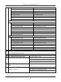
Contents
Section 1: Introduction
7
7
1.1 About the System
Section 2: Installation
12
2.1 Overview of Installation Process
12
2.2 Alarm Controller Installation
12
2.3 Wiring
13
2.4 Installing Modules
18
29
Section 3: Configuration
3.1 Basic Configuration Steps
29
3.2 Using the Keypad
29
3.3 Enrollment
30
3.4 Working with Partitions
32
3.5 Trouble Indicators
33
3.6 Keypad Partition Setup
33
3.7 Alternate Communicator Setup
35
3.8 Local Firmware Upgrade
36
3.9 Testing the System
36
Section 4: System Operation
37
4.1 Arming and Disarming
37
4.2 Partition vs. Global Keypad
37
4.3 Labels
38
4.4 Annunciation
39
4.5 Keypad Function Keys
39
4.6 Language Selection
42
4.7 [*] Commands
42
4.8 SMS Command and Control
55
4.9 Visual Verification
56
Section 5: Programming
57
5.1 How to Program
57
5.2 Programming Methods
57
5.3 Programming Descriptions
61
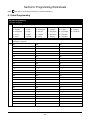
Section 6: Programming Worksheets
122
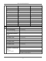
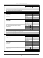
6.1 Label Programming
122
6.2 Zone Setup
127
6.3 System Times
130
6.4 Access Codes
132
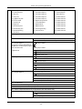
6.5 PGM Programming
132
6.6 System Lockout
145
6.7 System Options
145
6.8 Auto-Arm/Disarm
150
6.9 Partition and Zone Assignment
154
6.10 Communications
156
6.11 DLS Programming
166
-4-
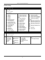
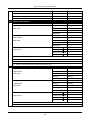
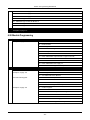
6.12 Virtual Inputs
166
6.13 Schedule Programming
167
6.14 Audio Module Programming
172
6.15 Wireless Programming
177
6.16 Alternative Communicators
178
6.17 Keypad Programming
178
6.18 Template Programming
180
6.19 System Information and Testing
180
6.20 Module Programming
181
6.21 Testing
182
6.22 Battery Settings
182
6.23 Restoring Factory Defaults
183
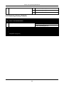
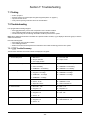
Section 7: Troubleshooting
184
7.1 Testing
184
7.2 Troubleshooting
184
Appendix 1: Reporting Codes
192
Appendix 2: Word Library
201
Appendix 3: Template Programming Tables
202
Appendix 4: Regulatory Approvals
208
Appendix 5: ASCII Characters
215
Appendix 6: Wiring Diagrams
216
Appendix 7: Specifications
219
8.0 Index
229
-5-
Section 1: Introduction
1.1 About the System
The PowerSeries Neo alarm panel is a feature-rich, scalable alarm system designed for residential and light commercial
use. The alarm panel supports both hardwired and wireless devices. This section lists the features of the alarm panel, available models, and compatible devices.
The following symbols are used to indicate features or methods of operation that are only available in a particular market. No
symbol indicates the feature or operation is available for all markets unless noted specifically otherwise.
CP-01
- North America
EN
- Europe
NFA2P
- France
UK
- United Kingdom
1.1.1 Features
The following features are available on the PowerSeries Neo alarm controller.
Zones, Wireless Keypads, Wireless Keys, Panic Pendents and Proximity Tags
l
l
l
l
l
16, 32, 64, or 128 wireless or hardwired zones supported, including 6 or 8 hardwired zones available on the controller.
40 zone types and 14 programmable zone attributes
Up to 16 separate wireless keypads supported
Up to 32 separate wireless keys or supported
Up to 94 separate proximity tags supported
Access Codes
l
l
Up to 97 access codes: 94 (level 2-EN) one system master code (level 3-EN), one installer code (level 3-EN), and
one maintenance code
Programmable attributes for each user code ("Access Code Attributes" on page 49)
Programmable Outputs (PGMs)
l
l
Up to 4 programmable outputs (PGM) on the alarm controller with 49 available options
22, 38, 80, 148 maximum programmable outputs
System Supervision Features
The PowerSeries Neo continuously monitors a number of possible trouble conditions and provides audible and visual indication at the keypad. Trouble conditions include:
l
l
l
l
l
l
l
l
l
l
AC power failure
Zone trouble
Fire trouble
Telephone line trouble
Communicator trouble
Low battery condition
RF jam
AUX power supply fault
Failure to communicate
Module fault (supervisory or tamper)
Additional Features
l
l
l
l
l
2-way wireless device support
Visual verification (images + audio)
Proximity tag support
PGM scheduling
Quick arming
-7-
Section 1: Introduction
l
l
l
l
l
User, partition, module, zone and system labels
Programmable system loop response
Keypad and panel software versions viewable through keypad
Doorbell zone type
Low battery PGM type
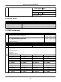
1.1.2 Available Models
The following alarm controller models are available:
l
l
l
l
l
HS2016-4
HS2016
HS2032
HS2064
HS2128
Note: Not all models are available in all markets.
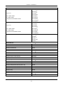
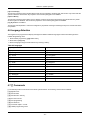
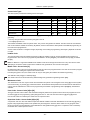
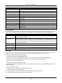
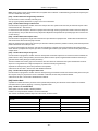
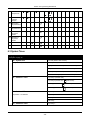
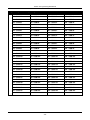
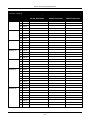
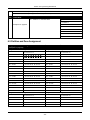
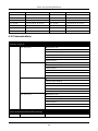
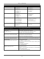
Model Differences
The table below lists the features of each alarm system model.
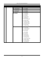
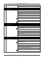
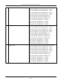
Table 1-1 Model Differences
Features
HS2128
HS2064
HS2032
HS2016
HS2016-4
Hardwired zones
128
64
32
16
16
Onboard zone inputs
8
8
8
6
8
Wireless zones
128
64
32
16
32
Partitions
8
8
4
2
8
Users
95
95
72
48
48
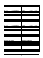
Onboard outputs
4
4
2
2
4
Max outputs
148
80
38
22
24
Keypads
16
8
8
8
8
Wireless keys
32
32
32
16
16
Wireless sirens
16
8
8
4
4
Wireless repeaters *
8
8
8
4
4
Proximity tags
94
94
71
47
47
Alt Comm. phone #’s
4
4
4
4
4
User-programmable phone #’s
8
8
8
8
8
Event buffer
1000
500
500
500
500
8-zone expander HSM2108
15
7
3
1
1
Power supply HSM2300
4
3
3
3
3
Power supply/high-current output expander
HSM2204
4
3
1
1
1
8-output expander HSM2208
16
8
4
2
2
2- way wireless integration module
1
1
1
1
1
Audio verification module HSM2955
1
1
1
1
1
*For UL installations, 2 repeaters must be installed for proper signal routing.
-8-
Section 1: Introduction
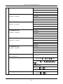
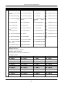
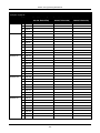
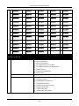
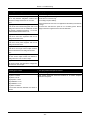
1.1.3 Compatible Devices
The following wireless devices and modules are compatible with this alarm controller.
Note: On the table below and throughout this document, x in the model number represents the operating frequency of the
device as follows: 9 (912-919 MHz), 8 (868MHz), 4 (433MHz).
Note: Only models operating in the band 912-919 MHz are UL/ULC listed where indicated. OnlyUL approved devices are to
be used with UL/ULC listed systems.
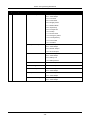
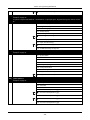
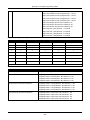
Table 1-2 Compatible Devices
Modules
Wireless keypads
HS2LCDWFx
HS2LCDWFPx
HS2LCDWFPVx
HS2LCDRFxUL
Hardwired keypads with 2-way wireless integration module
HS2LCDRFPxUL
HS2ICNRFx UL
HS2ICNRFPxUL
HS2LCDUL
Hardwired keypads
HS2LCDPUL
HS2ICNUL
HS2ICNPUL
HS2LEDUL
HS2TCHPUL
Touchscreen Keypad
Note: For ULC-s559 Listed applications the HS2TCHP touch screen keypad is for supplementary use
only.
2-way wireless integration module
HSM2HOSTx UL
8-zone expander
HSM2108UL
8-output expander
HSM2208UL
Power supply
HSM2300UL
4 high current output expander
HSM2204UL
Alternate communicator
3G2080UL
3G2080RUL
TL280UL
TL280RUL
TL2803GUL
TL2803GRUL
PCL-422UL
-9-
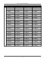
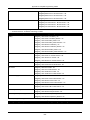
Section 1: Introduction
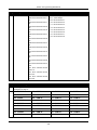
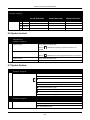
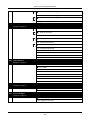
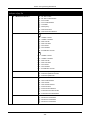
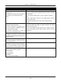
Hardwired Devices
2-wire smoke detector
FSA-210yUL
FSA-210yTUL
y= A, B, or C
FSA-210ySUL
FSA-210ySTUL
A: ULC listed models
FSA-210yRUL
B: UL listed models
FSA-210yRTUL
C: European and Australian models
FSA-210yRSUL
FSA-210yRSTUL
4-wire smoke detector
FSA-410yUL
FSA-410yTUL
x= A, B, or C
FSA-410ySUL
FSA-410ySTUL
A: ULC listed models
FSA-410yRUL
B: UL listed models
FSA-410yRTUL
C: European and Australian models
FSA-410yRSUL
FSA-410yRSTUL
CO detector
CO-12/24UL
12-24SIRUL
FW-CO12UL
FW-CO1224UL
CO1224UL
Wireless Devices
Wireless PG smoke detector
PGx926UL
Wireless PG smoke and heat detector
PGx916UL
Wireless PG CO detector
PGx913UL
Wireless PG PIR motion detector
PGx904(P)UL
Wireless PG PIR + camera motion detector
PGx934(P)UL
Wireless PG curtain motion detector
PGx924UL
Wireless PG dual tech motion detector
PGx984(P)
Wireless PG mirror motion detector
PGx974(P)UL
Wireless PG outdoor motion detector
PGx994UL
Wireless PG glass break detector
PGx912
Wireless PG shock detector
PGx935UL
Wireless PG flood detector
PGx985UL
Wireless PG temperature detector (indoor use)
PGx905UL
Outdoor temperature probe (requires PGx905)
PGTEMP-PROBE
Wireless PG key
PGx939UL
Wireless PG key
PGx929UL
Wireless PG panic key
PGx938UL
Wireless PG 2-button key
PGx949UL
Wireless PG indoor siren
PGx901UL
- 10 -
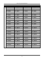
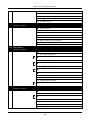
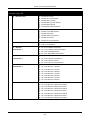
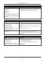
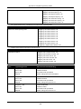
Section 1: Introduction
Wireless PG outdoor siren
PGx911UL
Wireless PG repeater
PGx920UL
Wireless PG door/window contact
PGx975UL
Wireless PG door/window contact w/ AUX
PGx945UL
Central Station Receivers
SG-System I, II, III, IV, 5
Enclosures
The HS2128/HS2064/HS2032/HS2016 main board can be installed in the metal enclosures listed below: Tamper
protection switches can be installed on all enclosures, including door opening protection and/or removal from the mounting
position. Doors can be secured using screws or keylock.
• Model PC5003C (removable door) made of 22Ga steel, painted, dimensions: 248mm(L) x 298mm(W) x 76mm(H), weight:
4.5Kg (with PCB, 7AH battery and transformer included)
• Model Power UC1 made of 18Ga steel, painted, dimensions: 315mm(L) x 319mm(W) x 100mm(H), weight: 6.15Kg (with
PCB, 7AH battery and transformer included).
....
For EN50131-1 Grade 2 compliant installations, all holes on the side of the cabinets shall be covered (plugged) if no
accessories are installed in the cabinet that will use these mounting holes.
The equipment enclosure shall be secured to the building structure before operation. Use 4 screws (appropriate for the wall
material on which it is attached) inserted through the four mounting holes provided in the back of the enclosure base.
- 11 -
Section 2: Installation
2.1 Overview of Installation Process
The steps below are provided to assist with the installation of the alarm system. Read over this section to get an overall
understanding of the order of installation. Working from this plan can help reduce problems and reduce the overall time
required for installation.
Step 1 – Create a Layout
Draw a rough sketch of the site and include all alarm detection devices, zone expanders, keypads and other required modules.
Step 2 – Mount the Panel
Decide on a location for the alarm panel and secure it to the wall using suitable mounting hardware. See "Mounting the
Enclosure" on page 12.
Step 3 – Wire the Alarm Controller
Wire each of the modules to the alarm controller following the guidelines provided in section "Corbus Wiring" on page 15.
Step 4 – Wire Zones
Complete all zone wiring. Follow the guidelines provided in section "Zone Wiring" on page 21 to connect zones using normally closed loops, single EOL resistor, double EOL resistors, fire zones and keyswitch arming zones.
Step 5 – Complete Wiring
Complete all other wiring including bells or sirens, telephone line connections, ground connections or any other wiring
necessary. Follow the guidelines provided in section "Terminal Descriptions" on page 13.
Step 6 – Power up the Control Panel
Once all zone and alarm controller wiring is complete, connect the battery before applying AC, and power up the system.
The alarm controller will not power up if only the battery is connected.
Step 7 – Enroll Keypads and Modules
All keypads must be enrolled in order to operate on the system. To enroll the first keypad, see "Enrolling the First Keypad "
on page 31. To enroll optional keypads, enter installer's programming section [902][000]. For more information, see "Module
Programming" on page 117.
Step 8 – Confirm Module Supervision
By default, all modules are supervised upon installation. Supervision is enabled at all times. To confirm that each module is
properly supervised, see "[903] Confirm Module" on page 118.
Step 9 – Enroll Wireless Devices
Wireless devices are enrolled via the wireless transceiver module (HSM2HOSTx) or RF keypad and Installer Programming
section [804]. See "Wireless Programming" on page 116 to enroll wireless devices.
Step 10 – Program the System
Section 5 on "Programming" on page 57 provides a complete description of how to program the alarm controller. It contains
complete descriptions of the various programmable features and options. Fill out the programming worksheets starting at
"Programming Worksheets" on page 122 completely before attempting to program the system.
Step 11 – Test the System
Test the panel completely to ensure that all features and functions operate as programmed.
2.2 Alarm Controller Installation
Begin the installation by mounting the alarm controller in the metal enclosure using the stand-offs provided. Optional modules, such as the HSM2108 and HSM2208, can also be mounted in the enclosure.
Install hardware in the sequence indicated on the following pages.
2.2.1 Mounting the Enclosure
Locate the panel in a dry area, preferably near an unswitched AC power source and the incoming telephone line. Complete
all wiring before applying AC or connecting the battery.
- 12 -
Section 2: Installation
2.3 Wiring
All wiring entry points on the enclosure are designated by arrows. All circuits are classified UL power limited except for the
battery leads. Minimum 1/4” (6.4mm) separation must be maintained at all points between power limited and non-power limited wiring and connections.
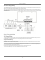
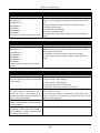
2.3.1 Terminal Descriptions
The following terminals are available on the PowerSeries Neo alarm controller.
Terminal
Description
BAT+, BAT- Battery terminals. Use to provide backup power and additional current when system demands exceed the
power output of the transformer, such as when the system is in alarm.
Do not connect the battery until all other wiring is complete.
AC
Power terminals.
Connect the battery before connecting the AC. Do not connect the battery or transformer until all other wiring
is complete.
AUX+, AUX- Auxiliary terminals. Use to power modules, detectors, relays, LEDs, etc. (700mA MAX). Connect the positive
side of device to AUX+, the negative side to AUX-.
BELL+,
BELL-
Bell/Siren power (700mA MAX). Connect the positive side of any alarm warning device to BELL+, the
negative side to BELL-.
RED, BLK, Corbus terminals. Use to provide communication between the alarm controller and connected modules. Each
YEL, GRN
module has four Corbus terminals that must be connected to the Corbus.
PGM1 to
PGM4
Programmable output terminals. Use to activate devices such as LEDs.
Z1 to Z8
COM
Zone input terminals. Ideally, each zone should have one detection device; however, multiple detection
devices can be wired to the same zone.
EGND
Earth ground connection.
(PGM1, PGM3, and PGM4: 50mA PGM2: 300mA or can be configured as an input)
TIP, RING, Telephone line terminals.
T-1, R-1
PCLINK_1
DLS/SA
PCLINK_2
DLS/SA, Alternate Communicator
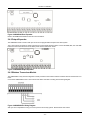
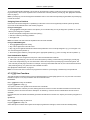
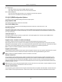
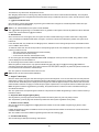
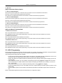
2.3.2 Wire Routing for Power & Non-Power Limited
All wiring entry points are designated on the diagram by arrows. All circuits are classified UL installation power limited
except for the battery leads which are not power limited.
A minimum ¼” (6.4mm) separation must be maintained at all points between power limited and non-power limited wiring
and connections. See "Wiring Diagrams" on page 216 for expanded diagrams.
Note: Wire entry for power limited wiring must be separated by a different entry access from non-power limited wiring.
- 13 -
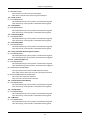
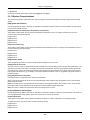
Section 2: Installation
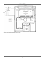
Figure 2-1 Wiring Routing (North America only)
- 14 -
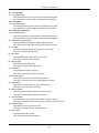
Section 2: Installation
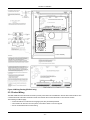
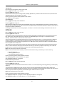
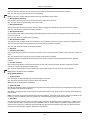
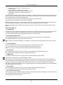
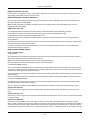
Figure 2-2 Wiring Routing (EN50131 only)
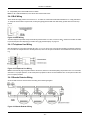
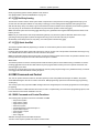
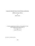
2.3.3 Corbus Wiring
The RED and BLK Corbus terminals are used to provide power while YEL and GRN are used for data communications. The
4 Corbus terminals of the alarm controller must be connected to the 4 Corbus terminals or wires of each module.
The following conditions apply:
l
l
l
Corbus should be run with minimum 22 gauge quad, two pair twisted preferred.
The modules can be home run to the panel, connected in series or can be T-tapped.
Do not use shielded wire for Corbus wiring.
- 15 -
Section 2: Installation
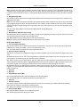
Note: Any module can be connected anywhere along the Corbus. Separate wire runs for keypads, zone expanders etc. are
not necessary.
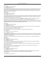
Note: No module can be more than 1,000'/305m (in wire length) from the panel. Do not use shielded wire for Corbus wiring.
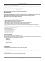
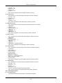
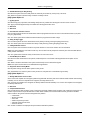
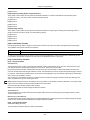
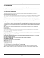
Figure 2-3 Corbus Wiring
Module (A) is wired correctly as it is within 1,000'/305m of the panel, in wire distance. Module (B) is wired correctly as it is
within 1,000'/305m of the panel, in wire distance. Module (C) is NOT wired correctly as it is farther than 1,000'/305m from the
panel.
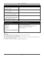
Current Ratings
In order for the system to operate properly, the power output of the alarm controller and power supply modules cannot be
exceeded. Use the following data to ensure that the available current is not exceeded.
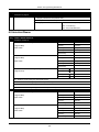
Table 2-1 System Output Ratings
Device
Output
Rating (12VDC)
AUX:
700mA. Subtract the listed rating for each keypad, expansion module and accessory
connected to AUX or Corbus. At least 100mA must be reserved for the Corbus.
BELL:
700mA. Continuous rating.
HS2016-4
HS2016
HS2032
HS2064
HS2128
2.0A. short term. Available only with standby battery connected. Not for UL/ULC or EN
certified applications.
HSM2208
AUX:
250mA. Continuous rating. Subtract for each device connected. Subtract the total load
on this terminal from the alarm panel AUX/Corbus output.
HSM2108
AUX:
100mA. Subtract for each device connected. Subtract the total load on this terminal
from the panel AUX/Corbus output.
- 16 -
Section 2: Installation
Alarm Controller Current Calculation
Maximum (Standby or Alarm)
AUX (700mA max. including PGMs 1-4)
Corbus (700mA max.)***
PCLink+ (Alt. Com.:125mA)
Total (must not exceed 700mA)
*** See "Corbus Current Calculation Chart" on page 17.
For UL, ULC and Commercial Listed applications, the total standby and alarm current cannot exceed 700mA.
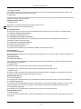
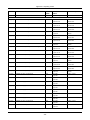
Table 2-2 Corbus Current Calculation Chart
Item
Current (mA)
x
Quantity Total (mA)
HS2016-4/HS2016/HS2032/HS2064/HS2128
85
X
1
HS2LCD
105
x
HS2ICN
105
x
HS2LED
105
x
HS2LCDP
105
x
HS2ICNP
105
x
HS2LCDRF
105
x
HS2ICNRF
105
x
HS2ICNRFP
105
x
HS2TCHP
160
x
30
x
40
x
HSM2300/2204*
35
x
HSM2HOSTx
35
x
Current required for connected devices =
HSM2108*
AUX output current of HSM2108
HSM2208*
AUX output current of HSM2208
HSM2955**
3G208(R)/TL2803G(R)/TL280(R)
x
125 (PCLINK)
Total Corbus Current =
- 17 -
x
85
Section 2: Installation
*These units draw current from the Corbus to power devices external to the module. This current must be added to the total
Corbus current. See manufacturer's specifications for the current draw of each device.
** For HSM2955 current draw refer to HSM2955 installation manual.
Line Loss
Voltage loss through wire resistance must be considered for all installations. To ensure proper operation, at least 12.5VDC
must be applied to all modules on the system (when AC is connected and the battery is fully charged). If less than 12.5VDC is
applied, system operation is adversely affected.
To correct the problem, try any or all of the following:
1. Connect a HSM2300/2204 power supply between the alarm controller and the module to provide additional power to the
Corbus.
2. Reduce the length of the Corbus run to the module.
3. Increase the gauge of wire.
Capacitance Limits
An increase in capacitance on the Corbus affects data transmission and causes the system to slow down. Capacitance
increases for every foot of wire added to the Corbus. The capacitance rating of the wire used will determine the maximum
length of the Corbus.
For example, 22-gauge, non-shielded, 4-conductor wire has a typical capacitance rating of 20 picofarads per foot (which is
20nF/1000’). For every 1000' of wire added – regardless of where it is run – the capacitance of the Corbus increases by
20nF.
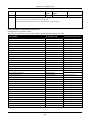
The following table indicates the total wire distance allowed for the capacitance rating of the wire used:
Table 2-3 Wire Capacitance
Wire Capacitance per 1000’ (300m)
Total Corbus Wire Length
15nF
5300’/1616m
20nF
4000’/1220m
25nF
3200’/976m
30nF
2666’/810m
35nF
2280’/693m
40nF
2000’/608m
2.4 Installing Modules
Remove all power from the system while connecting modules to the alarm controller.
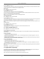
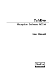
2.4.1 Zone Expander
The main alarm controller has connection terminals for zones 1 to 8. Additional HSM2108 zone expanders may be added to
increase the number of zones on the system. Each zone expander consists of one group of 8 zones. At enrollment, the zone
expander is automatically assigned to the next available zone slot. Connect the RED, BLK, YEL and GRN terminals to the
Corbus terminals on the alarm panel. Board current draw: 30mA.
- 18 -
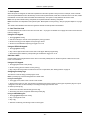
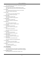
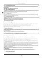
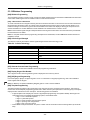
Section 2: Installation
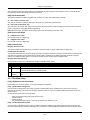
Figure 2-4 HSM2108 Zone Expander
Refer to the HSM2108 installation sheet for more information.
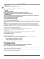
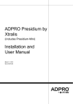
2.4.2 Output Expander
The HSM2208 module is used to add up to 8 low-current programmable outputs to the alarm system.
The 4-wire Corbus connection is used by the panel to communicate with the module. Connect the RED, BLK, YEL and GRN
terminals to the Corbus terminals on the alarm panel. Board current draw: 40mA.
Figure 2-5 HSM2208 Output Expander
2.4.3 Wireless Transceiver Module
The HSM2HOSTx 2-way wireless integration module provides communication between wireless devices and the alarm controller.
Connect the HSM2HOSTx to the 4-wire Corbus of the alarm controller according to the following diagram.
Figure 2-6 HSM2HOSTx Wiring Diagram
After you have completed the wiring, reconnect power to the security system. Board currant draw: 35mA
- 19 -
Section 2: Installation
2.4.4 Power Supply Wiring
The HSM2300/2204 power supply/high-current output module provides up to 1.0A of additional current and can be used to
add up to four programmable outputs (HSM2204 only) to the alarm system.
The 4-wire Corbus connection provides communication between the module and alarm panel. Connect the RED, BLK, YEL
and GRN terminals to the Corbus terminals on the alarm controller. If O1 is not used, connect to Aux with a 1K resistor. Board
current draw: 1.2A.
Figure 2-7 Power Supply Wiring
2.4.5 Keypad Wiring
To wire a keypad to the alarm controller, remove the keypad backplate (refer to the keypad installation sheet) and connect
the RED, BLK, YEL and GRN terminals to the corresponding terminals on the alarm controller.
Keypad Zone/PGM Wiring
Hardwired devices can be connected to hardwired keypads with inputs (zone) or outputs (PGM). This saves from running
wires back to the control panel for every device.
To connect a zone device to HS2LCD, HS2ICON, HS2LED and HS2TCHP keypads, run one wire to the P/Z terminal and the
other to B. For powered devices, use red and black to supply power to the device. Run the red wire to the R (positive) terminal and the black wire to the B (negative) terminal.
Keypad zones support Normally Closed Loops, Single End of Line and Double End of Line.
To connect the PGM output, run one wire to the P/Z terminal and the other to R.
- 20 -
Section 2: Installation
Figure 2-8 Keypad P/Z Terminals
Note: When using end of line supervision, connect the zone according to one of the configurations outlined in "Zone Wiring"
on page 21. End of line resistors must be placed on the device end of the loop, not at the keypad.
Assigning Keypad Zones
When using keypad zone inputs, each input used must be assigned a zone number in Installer Programming.
First, ensure that you have enrolled all installed keypads into the desired slots (See "[902] Add/Remove Modules" on page
117). Next, assign keypad zones by entering programming section [861]-[876], subsection 011 for keypads 1-16. Enter a 3digit zone number for each of the keypad zones. This number must be programmed into the slot location that the keypad is
assigned to.
Note: If a keypad zone input is assigned to zone number 1 to 8, the corresponding zone cannot be used on the main control
panel.
Once the keypad zones are assigned, you must also program zone definitions and zone attributes. See "[001] Zone Types"
on page 64 and See "Zone Setup" on page 64.
2.4.6 HSM2955 Wiring
For wiring information refer to HSM2955 Installation manual #29008435xxx.
2.4.7 Alternate Communicator Wiring
See Alternate Communicator installation manual.
2.4.8 Zone Wiring
Power down the alarm controller and complete all zone wiring.
Zones can be wired to supervise normally open devices (e.g., smoke detectors) or normally closed devices (e.g., door contacts). The alarm panel can also be programmed for single end-of-line or double end-of-line resistors.
Zone programming is done using the following programming sections:
l
l
l
[001] selects zone definition
[013] Opt [1] for normally closed or EOL; Opt [2] for SEOL or DEOL
[201 - 208] partition assignment.
Observe the following guidelines when wiring zones:
l
l
l
l
For UL listed installations use SEOL or DEOL only
Minimum 22 AWG wire, maximum 18 AWG
Do not use shielded wire
Do not exceed 100Ω wire resistance. Refer to the following table:
- 21 -
Section 2: Installation
Table 2-4 Burglary Zone Wiring Chart
Wire Gauge
Maximum Length to EOL Resistor (ft/meters)
22
3000 / 914
20
4900 / 1493
19
6200 / 1889
18
7800 / 2377
Figures are based on maximum wiring resistance of 100 Ω.
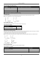
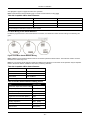
Normally Closed
Connect hardwired devices to any Z terminal and any Com terminal. Wire normally closed devices in series.
Note: For UL Installations, do not use normally closed loops.
Figure 2-9 Normally Closed
The following table shows zone status under certain conditions for NC Loops:
Table 2-5 NC Loop Status
Loop Resistance
Loop Status
0Ω (shorted wire, loop shorted)
Secure
Infinite (broken wire, loop open)
Violated
Single End-of-Line (SEOL) Resistor
When SEOL resistors are installed at the end of a zone loop, the alarm panel detects if the circuit is secure, open, or shorted.
The SEOL resistor must be installed at the end of the loop for proper supervision.
To enable SEOL supervision, program section [013], options [1] and [2] to OFF.
Note: This option should be selected if either normally closed or normally open detection devices or contacts are used.
Figure 2-10 SEOL Wiring
The following table shows zone status under certain conditions for SEOL:
Table 2-6 SEOL Loop Status
Loop Resistance
Loop Status
0Ω (shorted wire, loop shorted)
Violated
5600Ω (contact closed)
Secure
Infinite (broken wire, loop open)
Violated
- 22 -
Section 2: Installation
Double End of Line (DEOL) Resistors
When double end-of-line (DEOL) resistors are installed at the end of a zone loop, the second resistor enables the panel to
determine if the zone is in open, closed, tampered or faulted.
Note: Any zone programmed for Fire or 24-hr Supervisory must be wired with a SEOL resistor regardless of the type of zone
wiring supervision selected for the panel. If you change the zone supervision options from DEOL to SEOL or from NC to
DEOL, power the system down completely, then power it back up for correct operation.
To enable DEOL supervision, program section [013], option [1] to OFF and option [2] to ON.
Figure 2-11 DEOL Wiring
Note: If the DEOL supervision option is enabled, all hardwired zones must be wired for DEOL resistors, except for Fire and
24 Hour Supervisory zones. Do not use DEOL resistors for Fire zones or 24 Hour Supervisory zones.
Note: Do not wire Fire zones to keypad zone terminals if the DEOL supervision option is selected.
Note: This option can only be selected if N/C detection devices or contacts are used. Only one N/C contact can be connected to each zone.
The following table shows zone status under certain conditions for DEOL:
Table 2-7 DEOL Loop Status
Loop Resistance
Loop Status
0Ω (shorted wire, loop shorted)
Fault
5600Ω (contact closed)
Secure
Infinite (broken wire, loop open)
Tamper
11200Ω (contact open)
Violated
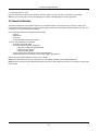
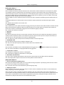
2.4.9 PGM Wiring
Min/max operating voltages for devices, sensors and modules is 9.5VDC - 14VDC.
PGMs switch to ground when activated from the alarm controller. Connect the positive side of the device to the AUX+ terminal and the negative side to a PGM terminal.
PGM 1, 3, 4 supply up to 50mA; PGM 2 supplies up to 300mA.
A relay is required for current levels greater than 50mA or 300mA. PGM2 can also be used for 2-wire smoke detectors, 24-hr
burglary input alarm.
Note: Use SEOL resistors on Fire zones only.
Figure 2-12 LED Output with Current Limiting Resistor and Optional Relay Driver Output.
- 23 -
Section 2: Installation
UL Compatibility ID For FSA-210B Series is: FS200
Note: For ULC listed installations, use FSA-210A and FSA-410A series.
2.4.10 Bell Wiring
These terminals supply 700mA of current at 10.4 - 12.5VDC for commercial/ residential installations. To comply with NFPA
72 Temporal Three Pattern requirements, section [013] Opt [8] must be ON. Note that steady, pulsed alarms are also supported.
Figure 2-13 Bell Wiring
The Bell output is supervised and power limited by 2A thermistor. If unused, connect a 1000Ω resistor across Bell+ and Bellto prevent the panel from displaying a trouble. See "[*][2] Trouble Display" on page 44.
2.4.11 Telephone Line Wiring
Wire the telephone connection terminals (TIP, Ring, T-1, R-1) to an RJ-31x connector as indicated in the following diagram.
For connection of multiple devices to the telephone line, wire in the sequence indicated. Use 26 AWG wire minimum for wiring.
Figure 2-14 Telephone Line Wiring
Note: Ensure that all plugs and jacks meet the dimension, tolerance and metallic plating requirements of 47 C.F.R. Part 68,
Sub-Part F. For proper operation, no other telephone equipment must be connected between the control panel and the telephone company facilities.
2.4.12 Smoke Detector Wiring
All zones defined as Fire must be wired according to the following diagram:
Figure 2-15 Smoke Detector Wiring
- 24 -
Section 2: Installation
See "[001] Zone Types" on page 64 for fire zone operation.
Note: Smoke detectors must be latching type. To reset a smoke detector, enter [*][7][2].
Table 2-8 Compatible 4-Wire Smoke Detectors
FSA-410B
FSA-410BLST
FSA-410BRST
FSA-410BT
FSA-410BR
FSA-410BLRST
FSA-410BS
FSA-410BRT
FSA-410BST
FSA-410BRS
Current ratings for DSC FSA-410 Series: 25mA - 90mA
Fire Zone Wiring: 2-wire Smoke Detectors
If PGM 2 is programmed for 2-wire smoke detector connection, the detectors must be wired according to the following diagram:
Figure 2-16 2-Wire Smoke Detector Wiring
Note: Additional 2-wire smoke detectors must be connected in parallel as shown above. The maximum number of smoke
detectors on a 2-wire loop is 18.
Note: Do not combine smoke detector models from different manufacturers on the same circuit. Operation may be impaired.
Refer to the smoke detector installation sheet when positioning detectors.
Table 2-9 Compatible 2-Wire Smoke Detectors
FSA-210B
FSA-210BR
FSA-210BT
FSA-210BRT
FSA-210BS
FSA-210BRS
FSA-210BST
FSA-210BRST
Current ratings for DSC FSA-210B series: 35mA - 75mA
Table 2-10 2-Wire Smoke Detector Initiating Circuit
Item
Specification
Style/Class, Supervised, Power Limited Style B (Class B)
Compatibility Identifier
HS2-1
DC Output Voltage
9.7-13.8 VDC
Detector Load
2mA (MAX)
Single End of Line Resistor (SEOL)
2200 Ω
Loop Resistance
24Ω (MAX)
Standby Impedance
3000Ω (NOM)
Alarm Impedance
1200Ω (MAX)
Alarm Current
86mA (MAX)
- 25 -
Section 2: Installation
2.4.13 CO Detector
The following hardwired CO detector models can be used with PowerSeries Neo alarm controllers:
l
l
l
l
Potter Model CO-12/24, UL File E321434
Quantum Model 12-24SIR, UL File E186246
NAPCO Model FW-CO12 or FW-CO1224, UL File E306780
System Sensor Model CO1224, UL File E307195
Note: For multiple unit connections, the leads between CO detectors must be broken. The power supervision relay must be
powered from the last detector in the loop.
Wireless CO detectors are also available. When installing wireless CO detectors, use only model PG9913 UL, PG8913,
PG4913. An HSM2HOSTx (x=9UL/8/4) wireless receiver or HS2LCDRF(P)x/HS2ICNRF(P)x (x=9 UL/8/4) wireless keypad are
required when installing wireless CO detectors. For more details on these wireless devices, refer to their respective installation manuals.
Note: Use only UL approved devices with UL/ULC listed systems.
Table 2-11 CO Detector Ratings
Device
Description
Max Rating @12VDC
CO-12/24
Potter model CO detector
40mA
12-24SIR
Quantum model CO detector
75mA
FW-CO12
NAPCO model CO detector
90mA
System Sensor model CO detector
40mA
FW-CO1224
CO1224
Figure 2-17 CO Detector Wiring
- 26 -
Section 2: Installation
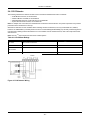
2.4.14 Ground Wiring
Figure 2-18 Ground Installation
Note: Using an insulated green wire (minimum 22AWG), connect the EGND terminal on the Corbus and the grounding wire
from the building electrical installation to any of the available holes on the back or side of the metal cabinet. See the diagram
attached to the cabinet for suggested GND point location and hardware recommendations.
Note: Wire and installation hardware not included.
2.4.15 Connecting Power
Batteries
Do not connect the battery until all other wiring is complete.
Note: A sealed, rechargeable, lead acid battery or gel type battery is required to meet UL requirements for power standby
times.
Connect the RED battery lead to the positive battery terminal and the BLACK battery lead to the negative battery terminal.
The panel can be programmed to charge the battery at 400mA or 700mA. (See "[982] Battery Settings" on page 120).
Note: Refer to "Aux Loading and Battery Selection" on page 1.
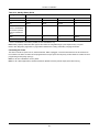
Battery Selection Chart
After calculating the battery capacity (B) for each specific installation use the following table to determine the battery
required to support the main panel in standby mode for
l
l
l
l
4 hours (UL commercial burglary/residential burglary),
12 hours (EN50131),
24 hours (UL/ULC residential fire, ULC commercial burglary, ULC commercial fire monitoring - no bell load allowed;
INCERT [Belgium]) or
36 hours (NFA2P [France]).
The battery size is measured in amp hours (Ah). The current values in the table denote the maximum current draw permitted
to achieve the desired standby time with the listed battery types.
- 27 -
Section 2: Installation
Table 2-12 Standby Battery Guide
Battery Size
Desired Standby Time
4h
12h
24h
36h
4Ah
700mA
------
------
------
7Ah
700mA
500mA
250mA
------
14Ah
700mA
470mA
------
(use 2 x 7Ah batteries
connected in parallel,
UL/ULC installations
only )
18Ah
------
------
------
300mA*
26Ah
------
------
------
500mA*
* use 2 x 7Ah batteries connected in parallel, UL/ULC installations only
Note: Battery capacity deteriorates with age and the number of charge/discharge cycles. Replace every 3-5 years.
Refer to See "Regulatory Approvals" on page 208 for detailed Aux. loading and battery charging information.
Connecting AC Power
The alarm controller requires a 16.5V, 40VA transformer. While unplugged, connect the transformer to the AC terminals on
the controller. The alarm controller can be programmed to accept a power line frequency of either 50Hz AC or 60Hz AC. See
programming section [024], option [1].
Note: For UL/ULC installations use only 60Hz.
Note: For ULC S559 applications, Standex transformer (Model FTC3716) shall be employed for direct-wiring.
- 28 -
Section 3: Configuration
3.1 Basic Configuration Steps
Once basic installation of the alarm panel is complete, the following general configuration options should be set:
l
l
l
l
l
l
l
l
l
l
l
l
l
l
l
l
create partitions, See "Working with Partitions " on page 32
assign keypads to partitions, see "Keypad Partition Setup " on page 33
assign sirens to partitions, see "Bell/Siren Operation " on page 32
create global zones, see "Global Zones " on page 33
set up partition account codes, see "Communications" on page 34
set up partition timers, see "System Times" on page 70
enroll wireless modules and devices, see "Enrolling Modules" on page 30
assign zone types, see "[001] Zone Types" on page 64, and attributes, see "[002] Zone Attributes" on page 68
create zone labels, see "Adding Labels" on page 61
add users, see "Assign Access Codes" on page 47
set up the alternate communicator if equipped, see "Alternate Communicator Setup" on page 35
program phone numbers, see "System Communications" on page 106
set up call directions for the central monitoring station, see "System Communications" on page 106
set up system timers, see "System Times" on page 70
configure reporting codes, see "Reporting" on page 100
test the system, see "Testing the System" on page 36
3.2 Using the Keypad
The PowerSeries Neo alarm panel is compatible with several different keypad types (see "Compatible Devices" on page 9);
However, all keypads have certain basic functionality in common.
3.2.1 Special Keys
Scroll symbols < > on keypads with LCD displays indicate that options can be viewed by pressing the scroll
These keys can also be used to position the cursor.
keys.
The [*] key is similar in function to the “Enter” key on a personal computer. It is generally used to accept the existing programming option. It is also the first key entry for [*] commands and can be used to enter the letters A-F when in Installer Programming mode.
The [#] key is similar in function to the “ESC” (escape) key on a personal computer. It is generally used to exit the current programming section or to return to the previous one.
3.2.2 LED Indicators
Keypads have the following status lights that provide visual indication of basic system status:
Ready: Panel is ready to be armed.
Armed: Panel is armed.
Trouble: System trouble. Enter [*][2] to view troubles.
AC Power: ON=AC present. OFF=AC absent.
Panel Status LED Operation
The red status LED, located on the alarm controller PCB, indicates the following:
l
l
l
Power up sequence – flashes rapidly until the end of the power-up sequence.
Firmware indication – flashes during the firmware upgrade process. If the firmware upgrade fails, the LED flashes rapidly.
Trouble indication – Flashes when troubles are present. Troubles are indicated according to the following priority:
1 flash - no keypads enrolled
2 flashes - module supervision trouble
3 flashes - bus low voltage
- 29 -
Section 3: Configuration
4 flashes - low battery trouble
5 flashes - AC trouble
6 flashes - AUX trouble
7 flashes - bell trouble
8 flashes - TLM trouble
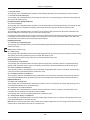
How to Enter Data
Conventions Used In This Manual
Brackets [ ] indicate numbers or symbols that must be entered on the keypad.
e.g., [*][8][Installer Code][804] requires the following key entries:
[*][8][5555][804]
[*] initiates a special command.
[5555] is the default installer code. The default installer code should be changed during initial programming of the system.
[804] indicates the particular programming section being accessed.
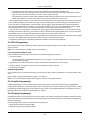
Entering Letters Manually (System Labels)
1. In Installer Programming, enter the section requiring text input.
2. Use the arrow keys [<][>] to move the cursor to a blank space or existing character.
3. Press the number key corresponding to the appropriate letter. Each number button accesses three letters and a number.
The first press of the number key displays the first letter. The second press displays the second letter, etc.
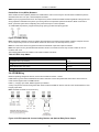
1
2
3
A, B, C, 1
4
D, E, F, 2
5
G, H, I, 3
6
J, K, L, 4
7
M, N, O, 5
8
P, Q, R, 6
9
S, T, U, 7
V, W, X, 8
0
Y, Z, 9,0
Space
4. To select lower case letters press [*]. The Select Options list opens. Scroll to “lower case” and press [*] again to select.
5. When the required letter or number is displayed use the arrow keys [<][>] to scroll to the next letter.
6. When finished, press the [*] key, use the [<][>] keys to scroll to “Save” then press [*].
7. Continue from step 2 until all labels are programmed.
For information on entering hexadecimal data, see "Programming Hex and Decimal Data" on page 60.
3.3 Enrollment
All optional modules and devices must be enrolled on the system. During enrollment, the electronic serial number (ESN) of
each device is identified to the control panel and zones are assigned. A wireless transceiver HSM2HOST or an RF keypad
must be enrolled first before wireless devices can be enrolled.
3.3.1 Enrolling Modules
During automatic and manual enrollment, if an attempt is made to enroll more than the maximum number of modules, an
error tone sounds and a message is displayed on LCD keypads.
Table 3-1 Module Capacity
Module
HS2016-4 HS2016 HS2032 HS2064 HS2128
HSM2108 8 Zone expander
1
1
3
7
15
HSM2208 8 Output expander
2
2
4
8
16
- 30 -
Section 3: Configuration
Module
HS2016-4 HS2016 HS2032 HS2064 HS2128
Wireless Keypad:
8
8
8
8
16
HS2TCHP Touchscreen Keypad
8
8
8
8
16
HSM2300 Power Supply 1A
3
3
3
3
4
HSM2204 4 High-current Output
1
1
1
3
4
HSM2HOSTx Transceiver
1
1
1
1
1
HSM2955
1
1
1
1
1
HS2LCDRF(P)4
HS2ICNRF(P)4
HS2LCDWF(P)(V)4
(not UL evaluated)
Modules can be enrolled automatically or manually using section [902] of Installer programming. For instructions on
enrolling modules, see "Module Programming" on page 117.
To confirm that a module has been successfully enrolled, use Installer Programming section [903]. See "[903] Confirm Module" on page 118 for details.
Enrolling the First Keypad
To enroll a hardwired keypad, connect the keypad to the alarm controller, power up the alarm panel then press any button
on the keypad.
To enroll a wireless keypad, first connect the HSM2HOSTx wireless integration module to the alarm controller. Next, power
up the alarm panel and a wireless keypad. Press any button on the keypad to enroll it on the HSM2HOSTx. The
HSM2HOSTx is then enrolled on the alarm panel. To enroll other keypads, see "Module Programming" on page 117.
3.3.2 Module Supervision
By default, all modules are supervised upon installation. Supervision is enabled at all times so that the panel can indicate a
trouble if a module is removed from the system.
To check which modules are currently connected and supervised, see "[903] Confirm Module" on page 118.
If a module is connected but is not recognized by the system, it may be due to any of the following reasons:
l
l
l
l
the module is incorrectly wired to the alarm controller
the module has exceeded its maximum wire run length
the module does not have enough power
the module is not enrolled on the wireless receiver
Removing Modules
Enrolled modules can be deleted from the system via programming section [902]. For instructions, see "[902] Add/Remove
Modules" on page 117.
3.3.3 Enroll Wireless Devices
Wireless devices are enrolled via the wireless transceiver module and Installer Programming section [804][000]. See "Compatible Devices" on page 9 for a list of supported wireless devices.
Wireless devices are enrolled using one of the following methods:
Auto Enrollment
To enroll a wireless device using this method, press and hold the Enroll button on the device for 2-5 seconds until the LED
lights then release the button. The alarm panel automatically recognizes the device and the keypad displays a confirmation
message. The device ID and next available zone number are displayed. Press [*] to accept or scroll to another available
zone number. Batteries must be installed in the wireless device in order to enroll.
Various zone features are programmable depending on the type of device. See "Zone Setup" on page 64 for details.
- 31 -
Section 3: Configuration
Pre-Enrollment
Pre-enrollment is a two step process. The first step requires entering each device ID ([804][001]-[716]). Every wireless device
has an ID printed on the sticker attached to the device. The format is XXX-YYYY where:
l
l
XXX identifies the type or model of the device
YYYY is a short encrypted ID used by the system to identify the specific device
Pre-enrollment can be done at a remote location and using DLS/SA. The second step is to press the enrollment button on
the device, usually done on location. Installer Programming does not have to be entered at this step. Both steps must be performed in order to complete the enrollment.
3.4 Working with Partitions
A partition is a limited area of the premises that operates independently from the other areas. Partitioning a system can be
beneficial if the property has outbuildings that need to be secured independently of a main area or if the home has a separate apartment.
Each partition can have its own keypad or a keypad can have access to all partitions (only if all partitions belong to the same
owner). User access to partitions is controlled via access codes. A master code can access the entire system and partitions,
while a user code is limited to assigned partitions.
Setting up a partition requires configuration of the following:
l
l
l
l
l
create the partition
define bell/siren operation
assign keypads
assign zones
assign users
3.4.1 Setting Up a Partition
Partitions are added or removed from the system by applying or removing a partition mask via Installer Programming section
[200]. The number of available partitions depends on the alarm panel model. See "[200] Partition Mask" on page 98 for more
information.
3.4.2 Bell/Siren Operation
Each partition must have a siren. The system siren connected to the bell output of the alarm controller can be mounted in a
central location within hearing range of all partitions. Each partition can also have wireless sirens activated only on the
assigned partition. See "Wireless Programming" on page 116 for details.
Single Siren Output Operation
With a siren shared across all partitions, control over activation/deactivation of the output depends on the partition that initiated the alarm sequence. Only the partition that originated the alarm can deactivate the bell output.
Global zones, such as smoke detectors shared by multiple partitions, can deactivate the siren on all partitions the zone is
assigned to.
Multiple Siren Output Operation
When multiple sirens are used in the installation, they can be programmed to sound alarm conditions for all partitions, or for
individual partitions by using a partition enable mask.
If hardwired sirens are used, this is accomplished via bus power supplies with a supervised high-current output. The output
is then programmed as a Fire and Burglary PGM output type.
Note: Only the first output of the HSM2204 output module has bell supervision. Some conditions, such as an installer system
test, may override the partition assignment and cause all sirens to activate. User system tests only activate the sirens/outputs
assigned to that partition.
- 32 -
Section 3: Configuration
3.5 Trouble Indicators
Both audible and visual trouble indications are available on all partitions. For more information, see "[*][2] Trouble Display"
on page 44.
Programming section [013] option 3 controls whether or not troubles are indicated when the alarm system is armed.
3.6 Keypad Partition Setup
Keypads can be configured to control an individual partition or all partitions. In general, a partition keypad controls the partition it is assigned to. A Global keypad controls all partitions. Global keypads should be placed in common areas of the
premises, such as points of entry or reception areas, where the ability to arm and disarm more than one partition at a time is
required.
Partition keypads can also be temporarily loaned to other partitions.
To select a keypad operating mode:
1. Enter Installer Programming: [*][8][installer code].
2. Select [861]-[876] to program keypads 1-16.
l
l
l
Press [000] for partition assignment.
For Global operation, key in 00.
To assign a keypad to a partition, key in 01-08 for partition 1-8.
3. Press the [#] and reapeat step 2 for next keypad. When finished programming all keypads, press the [#] key twice to exit
programming.
Users are assigned partition access rights via the [*][5] menu.
3.6.1 Loaned Partition Setup
To loan a keypad to another partition:
1. Press and hold [#]. The keypad switches to Global display.
2. Select a partition by pressing digits 1 to 8. The keypad is temporarily loaned to another partition.
If the keypad is inactive for more than 30 seconds, it reverts to its assigned partition.
3.6.2 Global Zones
If a zone is added to more than one partition, it becomes a global zone. A global zone is only armed when all assigned partitions are armed and is disarmed when any assigned partition is disarmed.
Global zones behave as follows:
l
l
l
l
A global Stay/Away type zone is not activated until all partitions the zone is assigned to are armed in the Away mode.
Interiors must be activated on all partitions for the global Stay/Away zone to be active.
A shared zone bypassed on one partition is bypassed on all partitions the zone is assigned to.
An entry delay started on a global zone sounds an entry delay on all keypads assigned to partitions the global zone
is assigned to.
A global Delay type zone follows the longest programmed delay time of the partitions it is assigned to.
3.6.3 Fire and CO Zone Types
Fire zones only place the partition they are assigned to into alarm. Other partitions retain their current state.
A fire reset only resets partitions they are assigned to.
One or more fire zones may be located on any partition.
On alarm, the fire auto-scroll display appears on all partition keypads and on all global keypads. Fire alarm silence and fire
system reset may be done directly on any partition keypad. To silence a fire or CO alarm from a global keypad requires that
the global keypad be loaned to one of the partitions the zone is assigned to.
- 33 -
Section 3: Configuration
3.6.4 Bell/PGM Support
PGMs must be assigned to one or more partitions. See section [007] for partition assignment.
Note: Bell PGM type requires supervision and follows arming squawks by partition.
3.6.5 Communications
Account codes are assigned to all system and partition events.
For SIA communications, a single account code (programmed in section [310][000]) is used for all events. The partition is
identified via Nri1-8. System events use Nri0.
When using communication formats other than SIA, individual account codes can be programmed for each partition. See "
[310] Account Codes" on page 106.
3.6.6 Assign Zones
Partition zone assignments are completed using sections [201] - [208] for partitions 1 - 8. Subsections [001 - 016] are then
used to enable or disable banks of 8 zones on the partition.
3.6.7 Assign Users
Acess [*][5] using the master code, select the desired user code and enter digit 4 to modify the partitions that can accept the
user code.
3.6.8 Factory Defaults
Individual modules, as well as the alarm panel itself, can have their programming returned to factory default settings. Hardware is defaulted via the following Installer Programming sections:
l
l
l
l
l
[991] Default Keypads
l
000 – Default all keypad programming
l
001-016 – Default keypads 1-8
[993] Default alternate communicator
[996] Default wireless receiver
[998] Default HSM2955
[999] Default system
See "Defaults" on page 121 for more information.
Default All labels
Use programming section [000][999]. The following labels are returned to factory default settings:
l
l
l
l
l
l
l
Zone Label
Partition Labels
Module Labels
Partition 1-8 Command Output 1 to 4 Labels
Schedule 1 to 4 Labels
Event Labels
User Labels
System and module programming is not affected.
Hardware Reset Main Control Panel
Perform the following to restore the main control panel to default settings:
1. Power down the system.
2. Remove all wires between Zone 1 and PGM 1 on the alarm controller.
3. Connect a short between Zone 1 and PGM.
4. Power up the system (AC only) for 60 seconds.
5. Power down the system and remove the short.
6. Power up the system again. Factory defaults are restored.
- 34 -
Section 3: Configuration
Hardware default is logged to the event buffer.
Note: Hardware default is not available when installers lockout is enabled.
3.7 Alternate Communicator Setup
The alternate communicator is an optional wireless or ethernet communications device that can be used as a backup to the
PSTN connection or as a primary means of communication between the alarm panel and the central monitoring station. The
alternate communicator communicates via 3G (HSPA) or Ethernet.
The following configuration steps are required to set up the alternate communicator:
l
l
l
l
l
l
l
Install the alternate communicator and wire it to the alarm panel (use PCLINK_2 header)
Enroll the alternate cellular communicator with Connect 24
Set the communication path: [300]
Enable the alternate communicator: [382] option 5
Enable event reporting: [307]/[308]
Program communication delay timer: [377]
Program DLS access: [401] option 07
Refer to the 3G2080(R)/ TL2803G(R)/ TL280(R) installation manual for details.
3.7.1 Real Time Clock
This feature synchronizes the alarm panel time and date with that of the alternate communicator, provided real time clock
support is available. Time and date are updated at 4:05 PM or when the system time is lost. This feature is enabled/disabled
in Installer Programming section [024] option 5.
3.7.2 Communication Paths
The path of communication between the alarm panel and the central station must be established through either the alarm
panel’s on-board Public Switched Telephone Network (PSTN) connection or through the alternate communicator (cellular or
Ethernet) if equipped.
Paths to four receivers can be programmed in Installer Programming section [300] options 001 - 004.
For more information, see "[300] Panel/Receiver Communication Paths " on page 99.
3.7.3 Communications Options
The following alarm panel options must be programmed when configuring the alternate communicator:
[300] option 02: communication path (see "[300] Panel/Receiver Communication Paths " on page 99)
[380] option 01: communications enabled/disabled (see "[380] Communicator Option 1" on page 109)
[382] option 05: enable communicator and all associated options: telephone number, reporting code and call direction ("
[382] Communicator Option 3" on page 111)
[308][351]-[356] reporting codes (see "[351] Alternate Communicator 1")
[401] option 7: DLS access (see "[401] System Test Events")
3.7.4 Communication Attempt Limit
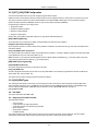
If a telephone line monitoring (TLM) trouble is present, the number of PSTN dialing attempts is reduced from the programmed value to 0 attempts. See programming section [380] Communicator Option 1 for details.
3.7.5 Supervision Restore
If the alarm system experiences a failure to communicate (FTC) with the central monitoring station, it automatically attempts
to transmit the event when communications are restored.
- 35 -
Section 3: Configuration
3.7.6 Remote Firmware Upgrade
Firmware upgrades can be automatically pushed to the alarm panel and modules from Connect 24 or DLS. A message is displayed on LCD keypads indicating a firmware upgrade is available. On all keypads, the blue proximity tag bar flashes one
second on - one second off.
Users authorize the firmware upgrade through [*][6][Master Code][17].
During the update, a message indicating that a firmware upgrade is in progress is displayed on the LCD keypad. If the firmware update fails, an error message is displayed on LCD keypads.
Firmware updates are performed under the following conditions:
l
l
l
l
l
l
l
The system is not armed
No AC trouble is present
No low battery trouble is present
No FTC trouble is present
Every alarm in memory has been viewed
No events are being communicated
An alternate communicator is present
Remote firmware upgrade is possible for the following modules:
l
l
l
hardwired keypads, including HS2LCDRF
wireless transceivers
alternate communicators
Note: For UL listed installations, do not use remote programming unless an installer is on the premises.
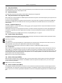
3.8 Local Firmware Upgrade
Alarm panel firmware can be upgraded locally via DLS. Firmware upgrade prevention rules are ignored when performing a
local firmware upgrade.
Note: [382][5] must be enabled to perform a local firmware upgrade.
To perform a local firmware upgrade:
1. Remove the front cover of the alarm panel and plug the DLS header into the PCLink 2 connector on the alarm controller.
2. Open the Flash Utility within DLS, select the latest firmware file from the Web or browse to a saved flash file on your hard
drive. Follow the steps as prompted by the Flash Utility application. A message is displayed when download is complete.
3. Once the firmware update is complete, the system powers up.
3.9 Testing the System
Installer Walk Test
Walk test enables the installer to test the operation of each detector by tripping zones, causing an actual alarm. Enter section
[901] to initiate a walk test. When a zone is tripped, all system sirens emit a tone to indicate that the zone is working correctly.
After 15 minutes without zone activity, the walk test terminates automatically. To manually exit walk test mode, enter [901]
again.
3.9.1 Viewing the Event Buffer
The event buffer contains logs of events that have occurred on the alarm system beginning with the most recent. The capacity of the event buffer is scalable and can hold 500/1000 events (depending on panel model) before rolling over. The buffer
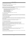
displays events according to their time stamp, beginning with the most recent. The event buffer can be uploaded using DLS.
Each event displays the time and date, a description of the event, the zone label, access code number or any other pertinent
information. To view the event buffer, press [*][6][Master Code][*].
- 36 -
Section 4: System Operation
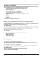
4.1 Arming and Disarming
The following table describes the various arming and disarming methods available.
Table 4-1 Arming/Disarming Methods
Method
Description
Away Arm
for 2 seconds + [Access Code*]
Stay Arm
for 2 seconds + [Access Code*]
Night Arm
when armed in stay mode [*][1] + [Access Code*]
Disarm
[Access Code]
No-Entry Arming
[*][9] + [Access Code]
Quick Arm/Quick Exit
[*][0]
* - requiring an access code can be programmed in Section [015]
For detailed arming/disarming instructions, see the PowerSeries Neo User Manual.
4.2 Partition vs. Global Keypad
Keypads can be configured to control an individual partition or all partitions (see "Keypad Partition Setup " on page 33).
Loaning a keypad to another partition does not require an access code; However, no function that requires an access code
can be performed on that partition unless the user’s code has sufficient permission.
4.2.1 Single Partition Operation
Single partition keypads provide access to alarm functionality for an assigned partition.
Single partition keypads behave as follows:
l
l
l
l
l
l
l
l
l
l
Display the armed state of the partition
Display open zones, if the zone belongs to the partition the keypad is on
Display bypassed zones and allow zone bypassing or creating bypass groups of zones assigned to the keypad partition
Display system troubles (system low battery, system component faults/tampers)
Display alarms in memory that occurred on the partition
Allow the door chime to be enabled/disabled
Activate system test (sounds bells/PGMs assigned to the partition)
Allow label programming ( user labels for the partition)
Control command outputs (those assigned to the partition, or global outputs such as smoke detector reset)
Display temperature (not evaluated by UL)
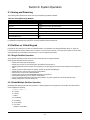
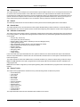
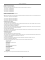
4.2.2 Global/Multiple Partition Operation
Global keypads display a list of all active partitions or assigned partitions along with their current state. The Global status
screen displays the following:
12345678 (RA!N----)
R = Ready
A = Armed
! = Alarm
N = Not Ready
X = Exit Delay
E = Entry Delay
P = Pre-Alert
- = Partition not enabled
- 37 -
Section 4: System Operation
In the following example, partition 1 is armed, partition 2 is disarmed and ready, partition 3 is disarmed and not ready, partition 4 is in alarm, partition 5 is indicating exit delay, partition 6 is in entry delay, partition 7 is in auto-arm pre-alert and partition 8 is not enabled.
1 2 3 4 5 6 7 8
A R N ! X E P Global keypads behave as follows:
l
l
l
Troubles are displayed and sounded on the global keypad. Troubles can be viewed from the global keypad display
by pressing the right scroll key then (*). The Troubles menu is displayed. An access code may be required to enter
the [*][2] menu depending on system programming.
Keypad function keys can be programmed for Global Stay Arm, Global Away Arm and Global Disarm.
Multiple partition arming may be done from a global keypad assigned to the same partitions as the user.
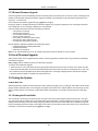
4.3 Labels
Various custom labels can be created to make identification of the alarm system, partitions, zones and modules simpler.
Labels are created by inputting text manually, by selecting words from the Word Library or by downloading/uploading using
DLS. See "Adding Labels" on page 61
4.3.1 System Label
This feature is used to program a custom label for the security system. This label is used in the event buffer when system
events occur. The maximum label size is 14 ASCII characters.
See "[100] System Label" on page 63 for programming details.
4.3.2 Zone Labels
Customized labels can be created for each zone on the alarm system. These labels are used on various displays and events
to identify the zone. The maximum label size is 14 x 2 ASCII characters.
See "[001]-[128] Zone Labels" on page 61 for more details.
4.3.3 Partition Labels
Each partition on the alarm system can have a unique label to identify it. This label is displayed on partition keypads and
event messages. The maximum label size is 14 x 2 ASCII characters.
See "[101]-[108] Partition 1-8 Labels" on page 63 for more details.
4.3.4 Module Labels
Labels can be created for the following optional system modules:
l
l
l
l
l
l
l
l
l
l
keypads
8 zone expander modules
8 output expander modules
wireless transceiver
power supply
4 high-current output module
alternate communicator module
audio module
siren
repeater
The maximum label size is 14 ASCII characters.
See "[801] Keypad Labels" on page 63 for more details.
4.3.5 Event Labels
Customizable labels can be created for the following events:
- 38 -
Section 4: System Operation
l
l
l
l
Fire alarm
Fail to arm
Alarm when armed
CO alarm
The maximum label size is 14 ASCII characters. See page 61 for more details.
4.3.6 Partition Command Output Labels
This feature is used to program custom labels for command outputs. These labels are used with output activation events in
the event buffer. The maximum label size is 14 x 2 ASCII characters. See "[201]-[208][001]-[004] Partition Command Output
Labels" on page 63 for more details.
4.4 Annunciation
4.4.1 Door Chime
The keypad can be programmed to use one of four different door chime tones for each zone on the system. Chime is active
only during the disarm state. Only one door chime option can be enabled for each zone.
l
l
l
l
l
Beeps
Bing-Bong
Ding-Dong
Alarm Tone
Zone Name - Voice Annunciation (HS2LCDWF keypads only)
Chime is enabled/disabled on a partition using the [*][4] command.
4.4.2 Temperature Display
Indoor and outdoor temperature can be displayed on system keypads if configured in keypad programming section [861][876]>[023] option 7, and sections [041]-[042]. Temperature is detected using wireless temperature sensors installed on the
system. Refer to "Compatible Devices" on page 9.
Global keypads only display outdoor temperature.
4.4.3 Low Temperature Warning
Keypads can be configured to detect low ambient temperature.
If the temperature at the keypad drops to 6° C ± 2° C (43° F ± 3°F), the keypad zone goes into alarm. When the temperature
rises above 9° C ± 2° C (48° F ± 3° F), the keypad zone is restored.
When this option is enabled, the keypad’s zone input functionality is disabled.
Refer to section [861]-[876]>[023] option 8 for more information.
Note: This feature has not been evaluated by UL/ULC.
4.5 Keypad Function Keys
Keypads have 5 programmable function keys that can be configured to perform one of the following actions:
Table 4-2 Function Key Programming Options
[00] Null Function Key
[17] Arm Interior
[02] Instant Stay Arm
[21]-[24] Command Output 1 to 4[*][71] - [*][74]
[03] Stay Arm
[29] Bypass Group Recall
[04] Away Arm
[31] Local PGM Activate
[05] [*][9] No-Entry Arm
[32] Bypass Mode
- 39 -
Section 4: System Operation
[06] [*][4] Chime On/Off
[33] Bypass Recall
[07] System Test
[34] User Programming [*][5]
[09] Night Arm
[35] User Functions [*][6]
[12] Global Stay Arm
[37] Time & Date Program
[13] Global Away Arm
[39] Trouble Display [*][2]
[14] Global Disarming
[40] Alarm Memory [*][3]
[16] Quick Exit
[61]-[68] Partition 1 to 8 Select
To program a function key:
1. Enter Installer Programming [*][8].
2. Enter section [861] for keypad 1 function key programming.
3. Enter [001] to [005] to select a function key to program.
4. Enter a 2-digit number to assign a function key operation - [00] - [68]. See table above.
5. Continue from step 3 until all function keys are programmed.
6. Press the [#] key twice to exit Installer Programming.
Programmed function keys must be pressed for 2 seconds in order to activate the function.
4.5.1 Function Key Definitions
This section provides detailed descriptions of each programmable function key option.
[00] Null Function Key
This option deactivates the function key. The key does not perform any function when pressed.
[02] Instant Stay Arm
This feature is similar to the Stay Arm function key, except that no exit delay is applied and the system arms immediately.
If no Stay/Away zone types are programmed, the alarm system arms in Away mode.
Note: Do not use this function with CP-01 installations.
[03] Stay Arm
Only perimeter zones are armed. Interior zones are bypassed regardless of whether or not delay zones are tripped during
the exit delay.
[04] Away Arm
All interior and perimeter zones are armed. CP-01 panels require an exit through a delay zone during the exit delay or the
system will arm the perimeter zones only.
[05] No-Entry Arm [*][9]
All Delay 1 and Delay 2 zones become instant zones. If a door or window is opened the system goes immediately into alarm.
This function is typically used when no occupants are expected to return to the site during the armed period. Activation of this
function key requires an access code. This function only works while the system is disarmed.
See "[*][9] No-Entry Arming" on page 55 for more information.
[06] Chime On/Off
This function turns the door chime on or off and is the equivalent of pressing [*][4]. The alarm system must be disarmed to
use this function. If option 7 in section [023] is enabled, this function key requires an access code.
[07] System Test
This function performs a system test when pressed and is the equivalent of entering [*][6][Access Code][04]. The alarm system must be disarmed to use this function. See See "[*][6] User Functions" on page 51 for more information.
[09] Night Arm
All perimeter and interior zones, excluding Night zones, are armed. This key only works while the system is disarmed or
armed in Stay mode.
If no Night type zones are programmed, the alarm system arms in Away mode with an audible exit delay. Exit delay is silent.
Arming in this mode activates the Away Arming PGM output.
- 40 -
Section 4: System Operation
[12] Global Stay Arm
This function arms all partitions assigned to the user in Stay mode, provided they are ready to arm. If a partition is not ready,
the system cannot be armed. An access code is required with this option.
[13] Global Away Arm
This function arms all partitions assigned to the user in Away mode, provided they are ready to arm. If a partition is not ready,
the system cannot be armed. An access code is required with this option.
[14] Global Disarming
This function disarms all partitions assigned to the user. An access code is required with this option.
[16] Quick Exit
Pushing this key allows the user to open and close an entry/exit door without disarming the system. This function is equivalent to entering [*][0] at the keypad while the partition is armed. If quick exit is not enabled on the system, or if the system is
disarmed, pressing this key causes an error tone. An access code is not required to use this key. See "[015] System Option
3" on page 87 for more information.
[17] Arm Interior
This key removes or enables automatic bypass on all Stay/Away zones (equivalent to pressing [*][1] while armed).
If this function is performed while stay armed and, Night zones are programmed, the system arms in Night mode. If no Night
zones are programmed, the system arms in Away mode. If armed in Night or Away mode, this key switches the system back
to Stay mode. Pressing this key does not switch the arming mode from Night to Away.
This key only works while the system is armed and requires an access code entry if section [015] option 4 is disabled.
[21]-[24] Command Output 1 to 4
This function controls command outputs 1-4 and is the equivalent of entering [*][7][X], where X is 1, 3 or 4.
An access code is required to use this function.
Selecting command output 2 is the equivalent of pressing [*][7][2] sensor reset. See "103 – Sensor Reset [*][7][2]" on page 73
for more information.
[29] Bypass Group Recall
This function bypasses all zones belonging to the bypass group.
Zones must be saved in the bypass group for this function key to operate. An access code is required to use this feature if
section [023] option 4 is enabled.
Note: Do not use with wireless keys.
[31] Local PGM Activate
This function controls a PGM connected to a keypad.
[32] Bypass Mode
This function places the keypad in Zone Bypass mode. Selecting this function is the equivalent of pressing [*][1] while disarmed. If an access code is required for bypassing, the user must enter the access code before using this function. An
access code is required if section [023] option 4 is enabled.
[33] Bypass Recall
This function bypasses the same set of zones that were bypassed the last time the partition was armed. This function is equivalent to pressing [999] while in the [*][1] menu. An access code is required to use this feature if section [023] option 4 is
enabled.
[34] User Programming
This function is the equivalent of entering [*][5]. A master or supervisor access code is required to use this function. This key
only works while the system is disarmed.
[35] User Functions
This function puts the keypad in user programming mode and is the equivalent of entering [*][6]. An access code is required
to use this function. If section [023] option 8 is off, only the Master or Supervisor code can access the [*][6] menu.
[37] Time & Date Program
This function places the keypad in date/time programming mode. A valid access code is required.
- 41 -
Section 4: System Operation
[39] Trouble Display
This function puts the keypad in trouble display mode and is equivalent to pressing [*][2]. This function only works while the
system is disarmed. This function key requires a code if section [023] option 5 is enabled.
[40] Alarm Memory
This function puts the keypad in alarm memory display mode and is equivalent to pressing [*][3]. This function only works
while the system is disarmed. This function key requires a code if section [023] option 6 is enabled.
[61]-[68] Partition 1 to 8 Select
This function selects partition 1-8 when the assigned key is pressed. Pressing and holding the key for 2 seconds selects the
next partition.
4.6 Language Selection
The keypad can be programmed to display messages and labels in different languages. Perform the following from the
Installer Programming menu:
1. Enter installer programming [*][8][installer code]
2. Enter section [000]>[000].
3. Select a language using the scroll buttons or by entering a hotkey:
Table 4-3 Languages
[01] – English
[15] – Greek
[02] – Spanish
[16] – Turkish
[03] – Portuguese
[18] – Croatian
[04] – French
[19] – Hungarian
[05] – Italian
[20] – Romanian
[06] – Dutch
[21] – Russian
[07] – Polish
[22] – Bulgarian
[08] – Czech
[23] – Latvian
[09] – Finish
[24] – Lithuanian
[10] – German
[25] – Ukrainian
[11] – Swedish
[26] – Slovakian
[12] – Norwegian
[27] – Serbian
[13] – Danish
[28] – Estonian
[14] – Hebrew
[29] – Slovenian
4. Press [#] to exit.
4.7 [*] Commands
[*] commands provide convenient access to alarm system features. The following commands are available:
[*][1] Bypass zones
[*][2] View troubles
[*][3] View alarms in memory
[*][4] Door chime on/off
[*][5] User programming
[*][6] User functions
[*][7] Command output 1-4 on/off
[*][8] Installer programming mode
- 42 -
Section 4: System Operation
[*][9] No entry arming
[*][0] Quick arm/Exit
While in a [*] command menu, use the [*] key to select an option and the [#] key to exit to the previous screen. On an LCD
keypad, use the scroll keys to view options.
4.7.1 [*][1] Bypass or Stay/Away/Night Zones
The [*][1] command functions differently depending on whether the system is armed or disarmed.
Note: For UL/ULC listed installations, group bypass is not allowed.
When The Alarm System is Disarmed
Users can bypass individual zones or a programmed group of zones using the [*][1] keypad command. Zones are commonly
bypassed if users want to have access to an area while the partition is armed, or to bypass a defective zone (bad contact,
damaged wiring) until service can be provided. A bypassed zone does not cause an alarm.
When the partition is disarmed, all zones that were bypassed using [*][1] are no longer bypassed, except for 24-hr zones.
If the Code Required for Bypass option is enabled, an access code is required to enter bypass mode. Only access codes
with the Bypass attribute enabled can bypass zones (see "Access Code Attributes" on page 49).
Bypassing zones with an LCD keypad:
1. Ensure the system is disarmed.
2. Press [*] to enter the function menu. The keypad displays “Press [*] for < > Zone Bypass.”
3. Press [1] or [*], then key in your access code (if required).
4. Scroll to a zone or key in the three-digit zone number. Only zones enabled for zone bypassing are displayed. Enter the 3digit zone number or scroll to the desired zone and press [*] to bypass the zone.
“B” appears on the display to indicate the zone is bypassed. If a zone is open, “O” appears on the display. When an open
zone is bypassed, the “O” is replaced by “B.”
5. To clear a bypassed zone, repeat the above procedure. The “B” disappears from the display indicating that the zone is
no longer bypassed.
6. To exit bypass mode and return to the ready state, press [#].
Bypassing zones with a LED/ICON keypad:
1. Ensure the system is disarmed.
2. Press [*][1], then enter your access code (if required).
3. Enter the three-digit number of the zone(s) to be bypassed. The zone light turns on to indicate that the zone is bypassed.
4. To clear a bypassed zone, repeat the above procedure. On LED keypads, the zone light turns off to indicate that the zone
is no longer bypassed.
5. To exit bypass mode and return to the ready state, press [#].
Note: LED Keypads display the bypass status of zones 1-16 only.
Other Bypass Features:
The following features are also available on the [*][1] zone bypass menu:
Bypass Open Zones
Displays all currently open or bypassed zones. Use the scroll keys to view zones. Open zones are indicated by an (O). To
bypass a zone, press [*]. A bypassed zone is indicated by a (B).
Note: Zones with tampers or faults must be manually bypassed.
Bypass Group
Displays a programmed group of zones (bypass group) commonly bypassed. Press [*] to bypass all zones in the group.
Program Bypass Group
To program a bypass group, bypass all desired zones then select Bypass Options > Program Bypass Group. The selected
zones are saved to the bypass group. When finished, press [#] to exit.
In order to program a bypass group, a master or supervisor code with access to the appropriate partition must be used.
- 43 -
Section 4: System Operation
Bypass Recall
Press [*] while in this menu to bypass the same group of zones that were bypassed the last time the partition was armed.
Clear Bypasses
Press [*] to clear all bypasses.
Shortcuts from the [*][1] base menu:
991 = bypass group
995 = program group 1
998 = bypass open zones
999 = bypass recall
000 = clear group
When The Alarm System is Armed
When the system is armed, pressing [*][1] toggles between stay, away or night arming. If a night zone is on the system, pressing [*][1] either prompts the user for an access code if required, or sounds an acknowledgment tone and changes the arming
mode.
Note: If section [022], Option 5 [Stay/Away Toggle] is on, the system does not change from Away to Stay mode.
The zone attribute for zone bypassing must be enabled (see section [002] Zone Attributes, Option 04).
Holdup zones should not be part of bypass groups.
A zone that is manually bypassed via [*][1] will bypass the alarm, fault, and tamper conditions when DEOL is used.
If a 24-hour zone is bypassed, ensure that the zone is restored or disabled before removing the bypass.
4.7.2 [*][2] Trouble Display
This feature is used to view system troubles. If a trouble is present, the keypad Trouble indicator illuminates and an audible
indication is emitted (two short beeps every 10 seconds, except while in AC failure). Silence the audible indicator by pressing [#].
Troubles may be viewed while the system is armed or disarmed. The system may be programmed to show all troubles while
armed or only fire troubles. See section [13] option 3 on page 86 for details.
The system can be configured to require a user code to view [*][2] system troubles. See section [023] option 5.
To view trouble conditions:
l
l
l
Press [*][2] to enter the Trouble menu.
On an LCD keypad, scroll to a trouble type then press [*] to view the specific trouble. The zone name and trouble condition for each trouble are displayed on the screen.
On LED/ICON keypads, zone indicator lights illuminate to identify existing trouble types (e.g., Zone light 1 represents
Service Required trouble type). Press the number key corresponding to a zone light to view the specific trouble.
Lights 1-12 illuminate to indicate the trouble as follows:
Table 4-4 : Trouble Indications
Trouble 01 – Service Required:
[01] Bell Circuit Trouble: The bell circuit is open.
[02] RF Jam: The HSM2HOSTx has detected an RF Jam condition.
[03] Aux Supply Trouble: The alarm controller, HSM2204 or HSM2300 has an overcurrent condition on Aux.
[04] Loss of Clock: System time and date require programming.
[05] Output 1 Fault: An HSM2204 module has detected an open condition on output #1.
- 44 -
Section 4: System Operation
Trouble 02 – Battery Trouble:
[01] Panel Low Battery Trouble: The battery voltage (under load) is below 11.5V. Restores at 12.5V.
[02] Panel No Battery: No battery connected to alarm controller.
[04] HSM2204 01 - 04 Low Battery: An HSM2204 has a battery voltage less than 11.5V.
[05] HSM2204 01 - 04 No Battery: No battery connected to HSM2204.
[07] HSM2300 01 - 04 Low Battery: An HSM2300 has a battery voltage less than 11.5V
[08] HSM2300 01 - 04 No Battery: No battery connected to HSM2300.
Trouble 03 – Bus Voltage:
[01] HSM2HOSTx Bus Low Voltage: The HSM2HOSTx module has measured less than 6.3V on its Aux input.
[02] Keypad 01 - 16 Bus Low Voltage: A hardwired keypad has a bus voltage of less than 6.9V for ICON/LCD (RF version)
and 7.7V for non-RF models.
[04] HSM2108 01 - 15 Bus Low Voltage: A zone expander has a bus voltage of less than 5.9V.
[05] HSM2300 01 - 04 Bus Low Voltage: A power supply has a bus voltage of less than 6.9V.
[06] HSM2204 01 - 04 Bus Low Voltage: A high current output module has a bus voltage of less than 6.9V.
[08] HSM2208 01 - 16 Bus Low Voltage: The low current output module has detected a voltage less than 5.9V on its aux
input.
[09] HSM2955 Bus Low Voltage: The audio module has detected a voltage less than 9.65V on its aux input.
Trouble 04 – AC Troubles:
[01] Zone 001 - 128 AC Trouble: An AC trouble has been detected on a PGX934 PIR + Camera.
[03] Siren 01 - 16 AC: A siren has an AC trouble.
[04] Repeater 01 - 08 AC: A wireless repeater has an AC trouble.
[05] HSM2300 01 - 04 AC: An HSM2300 has an AC trouble.
[06] HSM2204 01 - 04 AC: An HSM2204 has an AC trouble.
[07] Panel AC: The alarm controller has an AC failure condition.
Trouble 05 – Device Faults:
[01] Zone 001 - 128: A zone is in fault. Additional information displayed on LCD keypads for the following troubles: Fire
Trouble (2-W Smoke, PGX916, PGX926), Freeze (PGX905), Self Test (PGX984), CO (PGX913), and Probe Disconnected
(PGX905). Also generated by a short on hardwired zones when DEOL is used or by a wireless supervisory fault.
[02] Keypad 01 - 16: A wireless or hardwired keypad is in fault.
[03] Siren 01 - 16: A siren is in fault.
[04] Repeater 01 - 08: A wireless repeater is in fault (supervisory or loss of AC/DC).
Trouble 06 – Device Low Battery:
[01] Zone 001- 128: Wireless zone has a low battery.
[02] Keypad 01-16: Keypad has a low battery.
[03] Siren 01 - 16: Siren has a low battery.
[04] Repeater 01 - 08: Repeater has a low battery.
[05] User 01 - 95: Wireless Key has a low battery.
Trouble 07 – Device Tampers:
[01] Zone 001 - 128 Tamper: A wireless or hardwired zone configured for DEOL operation is in tamper.
[02] Keypad 01 - 16 Tamper: A hardwired or wireless keypad is in tamper.
[03] Siren 01 - 16 Tamper: A wireless siren is in tamper.
[04] Repeater 01 - 08 Tamper: A wireless repeater is in tamper.
[05] Audio Station 01 - 04 Tamper: An audio station connected to an HSM2955 is in tamper.
- 45 -
Section 4: System Operation
Trouble 08 – RF Delinquency Trouble:
[01] Zone 001 - 128 RF Delinquency: No response from a wireless zone for 13 minutes. This trouble prevents arming until
acknowledged or cleared using [*][2].
[02] Keypad 01 - 16 RF Delinquency: No response from a wireless keypad for 13 minutes.
[03] Siren 01 - 16 RF Delinquency: No response from a wireless siren for 13 minutes.
[04] Repeater 01 - 16 RF Delinquency: No response from a wireless repeater for 13 minutes.
Trouble 09 – Module Supervisory Trouble:
[01] HSM2HOSTx not responding.
[02] Keypad 01 - 16 not responding.
[04] HSM2108 01 - 15 not responding.
[05] HSM2300 01 - 04 not responding.
[06] HSM2204 01 - 04 not responding.
[08] HSM2208 01 - 16 not responding.
[09] HSM2955 is not responding.
Trouble 10 – Module Tamper:
[01] HSM2HOSTx Tamper.
[02] Keypad 01 - 16 Tamper.
[04] HSM2108 01 - 15 Tamper.
[05] HSM2300 01 - 04 Tamper.
[06] HSM2204 01 - 04 Tamper.
[08] HSM2208 01 - 16 Tamper.
[09] HSM2955 Tamper
Trouble 11 – Communications:
[01] TLM: Telephone line disconnected from control panel.
[02] Receiver 01-04 FTC Trouble: Failure to communicate using programmed receiver paths.
[03] Alt. Comm SIM Lock: SIM card has incorrect or unrecognized PIN.
[04] Alt. Comm Cellular: Radio or SIM card failure, low signal strength detected, or cellular network fault.
[05] Alt. Comm Ethernet: Ethernet connection unavailable. A valid IP address is either not programmed or the module was
unable to get an IP with DHCP.
[06] Receiver 01-04 Absent: Alternate communicator unable to initialize a receiver.
[07] Receiver 01-04 Supervision: Alternate communicator unable to communicate with a receiver.
[09] Alt. Comm Fault: The alternate communicator has stopped responding.
[10] Alt Comm FTC Trouble: The alternate communicator has failed to communicate an internal event not generated by the
panel.
Trouble 12 – Not Networked Troubles:
[01] Zone 001-128 Not Networked Trouble: Generated when a zone becomes out of sync with the wireless network or has
not been synchronized with the network after enrollment.
[02] Keypad 01-16 Not Networked Trouble: Generated when a keypad becomes out of sync with the wireless network or
has not been synchronized with the network after enrollment.
[03] Siren 01-16 Not Networked Trouble: Generated when a siren becomes out of sync with the wireless network or has
not been synchronized with the network after enrollment.
[04] Repeater 01-08 Not Networked Trouble: Generated when a repeater becomes out of sync with the wireless network or
has not been synchronized with the network after enrollment.
[05] User 01 - 95 Not Networked Trouble: Generated when a wireless key becomes out of sync with the wireless network
or has not been synchronized with the network after enrollment.
- 46 -
Section 4: System Operation
IMPORTANT!
Ensure you have the following information available before contacting Customer Support :
l
Alarm controller type and version, (e.g., HSM2064 1.0):
Note: Version number can be accessed by entering [*][Installer Code][900] on any LCD keypad. This information is also located on a sticker on the printed circuit board.
l
List of modules connected to control panel, (e.g., HSM2108, HSM2HOSTx etc.) .
4.7.3 [*][3] Alarm Memory Display
The Memory light flashes if an alarm, tamper or fault event occurred during the last armed period or while the panel was disarmed (24 hour zones). Press [*][3] to view zones in alarm memory. To clear the memory, arm and disarm the system. When
viewing alarms in memory, LCD keypads indicate the last zone that has gone into alarm first, followed by other alarms in
numerical order.
This feature can be programmed to require an access code. See "[023] System Option 11" on page 94, option 6 for details.
A programmable function key may be configured to display alarms in memory. See "Keypad Function Keys" on page 39 for
details.
4.7.4 [*][4] Door Chime Enable/Disable
When this feature is enabled, the keypad emits a tone whenever a zone programmed as a Chime type is opened or closed.
Pressing [*][4] toggles between enabled and disabled. The door chime attribute for each zone is programmed in section
[861]-[876], subsections [101]-[228].
A function key can also be programmed to enable/disable this feature. See "Keypad Function Keys" on page 39 for details.
This feature may require an access code. See "[023] System Option 11" on page 94, option 7 for details.
The following door chime sounds may be selected:
l
l
l
l
l
6 beeps
"Bing-Bong"
"Ding-Dong"
Alarm tone
Zone Name -Voice Annunciation (HS2LCDWF keypads only)
4.7.5 [*][5] Program Access Codes
Use this section to perform the following functions:
l
l
l
l
l
press [1] to program user codes 02-95, and master code 01
press [2] to enroll a proximity tag
press [3] to add a custom label for each user
press [4] to assign users to partitions
press [5] to program user attributes
Assign Access Codes
In order to access alarm system functionality, users must be added to the system. This involves creating a unique access
code and assigning attributes to each user. Access codes are programmed via the [*][5] menu.
- 47 -
Section 4: System Operation
Access Code Types
The alarm system provides the following access code types:
Code
Add User
Delete User
Arm
Disarm
[*][5]
[*][6] [*][8]
Installer
No
No
No
No
No
No
Yes +
Master
All*
All
Yes
Yes
Yes
Yes
No
Maintenance
No
No
Yes
Yes
No
No
No
User
No
No
Yes
Yes
No
No** No
Supervisor
All but Master
All but Master
Yes
Yes
Yes
Yes
No
Duress
No
No
Yes
Yes
No
No
No
One-time use
No
No
Yes
1/day
No
No
No
+ If section [020] option 7 is on, a user must enter [*][6][Master Code][05] to give the installer permission to access programming.
* Can only change master code if section [015] option 6 is off.
** Yes if [023] option 8 is on.
The Installer and Master codes are system codes. They can be changed but not deleted. The other codes are user-defined
and can be added or deleted as necessary. By default, access codes have the same partition and attribute programming as
the code used to program them.
Access codes are either 4 or 6 digits in length, depending on the setting of programming section [041]. Duplicate codes are
not valid.
Installer Code
This code provides access to Installer Programming [*][8]. The installer code can access all partitions and perform any
keypad function. This code can be programed by the installer in section [006][001]. The default is 5555 (4-digit) or 555555
(6-digit).
EN Note: For EN50131-1 approved installations the installer code cannot change the master code or any other level 3 codes.
Attempting to access the master code from the installers code generates an error tone from the system.
Master Code - Access Code [01]
By default the master code can access all partitions and can perform any keypad function. This code can be used to program
all access codes, including the supervisor and duress codes.
If section [015] option 6 is on, the master code can only be changed by the installer via Installer Programming.
The default is 1234 (4-digit) or 123456 (6-digit).
EN The master code can be returned to factory default settings using Installer Programming section [989].
Maintenance Code
The maintenance code can only be used to arm and disarm the system. It cannot bypass zones. Use [*][9] to arm the system,
cancel auto-arming, or perform [*][7] command functions. No arm/disarm bell squawks are sounded when the maintenance
code is used. The Maintenance code can be programed by the installer in programming section [006][003]. The default is
AAAAAA.
User Codes - Access Codes [02] to [95]
This type of access code is used to arm and disarm assigned partitions and perform other functions as programmed. It can
access the [*][6] menu if programming option [023] option 8 is on. This code cannot access the [*][5] and [*][8] menus.
User access codes are created by the master user or supervisor users.
Supervisor Codes - Access Codes [02] to [95]
A supervisor code is a user code with the Supervisor attribute enabled. Users with this attribute can access the [*][5] and [*]
[6] user code programming section for the partition they are assigned to. However, these codes can only program codes
which have equal or lesser attributes. These attributes are changeable via the [*][5] menu. A supervisor code is created by
the master user or other supervisor users.
- 48 -
Section 4: System Operation
Duress Codes - Access Codes [02] to [95]
Duress codes function the same as user access codes, except they transmit a duress reporting code when used to perform
any function on the system.
Duress codes cannot be used to access [*][5], [*][6] or [*][8] menus.
Duress codes are created by the master user or supervisor users.
Note: Section [019] option 6 must be on to select the Duress Codes attribute.
One Time Use Code
A one time use code is a user code with the One Time User attribute enabled. This access code enables the user to arm the
alarm system an unlimited number of times. However, a user with this code can only disarm the system once per day. The
ability to disarm is reset at midnight or when the one time user code is keyed in by the master code user.
Note: One time use code cannot be applied to wireless keys.
One time use codes are created by the master user or supervisor users.
To add an access code using an LCD keypad:
1. Press [*][5][master/supervisor code] to edit access codes 02-95.
2. Use the scroll keys to select a user then press [*] to edit.
3. On the “Press (*) for Access Code” menu, press [*]. The current access code is displayed.
4. Key in the new access code. The code is saved when the last number is keyed in.
To erase an access code, select the user number and enter [*] as the first digit. All digits of the access code must be
entered.
A “-” beside a user code indicates it is not programmed. A “P” indicates the code is programmed. A “T” indicates the code is
programmed and a proximity tag is enrolled.
On an LED/ICON keypad:
1. Press [*][5][master/supervisor code]
2. Key in a 2-digit user number.
3. Press [1] to select access code.
4. Key in a new access code.
Access Code Attributes
Each user code has 6 attributes that can be toggled on or off.
The default attributes of an access code are the same as the code used to enter [*][5], whether a new code is programmed or
an existing one is edited. The available attributes are as follows:
l
l
l
l
l
l
Supervisor
Duress code
Zone bypassing
Remote access
Bell squawk
One time use code
1 – Supervisor
Converts standard user into supervisor user. See " " on page 47 for details.
2 – Duress Code
Converts standard user code into duress code. See " " on page 47 for details.
3 – Zone Bypassing
Users with this attribute can bypass zones. Section [023] option 4, Access code required for [*][1], must be on to use this
attribute.
4 – Remote Access
Users with this attribute can access the alarm system remotely via SMS.
- 49 -
Section 4: System Operation
7 – Bell Squawk
When this option is assigned, the main bell squawks when the alarm system is away armed. For example, use the arm/disarm bell squawk attribute to have wireless key access codes squawk the bell, while other codes are silent. To do this, enable
this attribute on all access codes associated with wireless keys. This option is off by default for all access codes.
Note: One squawk indicates arming completed; two squawks indicates disarming completed.
Note: This feature is independent of the system option “Bell Squawk on Away Arming.” See "[017] System Option 5" on page
89
The master code's attributes cannot be changed from default. The bell squawk is off at default.
8 – One Time Use Code
Converts standard user code into one time use code. See " " on page 47 for details. Do not apply this code to users with wireless keys assigned.
Using an LCD keypad:
1. Press [*][5][Master Code].
2. Use the scroll keys to choose a user (02-95) then press [*] to select.
3. Scroll to “Press [*] for User Options” then press [*] to select.
4. Scroll to a user attribute and press [*] to toggle it on or off.
Using an LED/ICON keypad:
1. Press [*][5][Master Code].
2. Key in the 2-digit number of the access code to edit. [5] for attribute programming.
3. Press the keypad number key corresponding to an attribute to toggle it on or off.
Add User Labels
Custom labels can be programmed for each user to more easily identify them on the alarm system. Labels can be a maximum of 16 characters.
Using an LCD keypad:
1. Press [*][5] then select a user (02-95).
2. On the “Press [*] for User Labels” screen, press [*].
3. Key in the custom user label. For instructions on how to input labels, See "Adding Labels" on page 61
Assigning Proximity Tags
This section is used to assign proximity tags to users.
Note: A proximity tag cannot be assigned to the master code.
Using an LCD keypad:
1. In the [*][5] menu, select a user or enter a user number.
2. Select “Press [*] for Prox Tag”, then pass the enrolled tag near the tag reader on the keypad. A proximity tag can only be
assigned to one user at a time. Invalid (un-enrolled) proximity tags cannot be used.
To delete a proximity tag:
1. Select a user and then select Press [*] for Prox Tag.
2. Press the [*] key when prompted to delete the proximity tag.
Using an LED/ICON keypad:
1. Press [*][5][Master/Supervisor Code].
2. Key in a 2-digit user code.
3. Key in [2].
4. Pass the enrolled tag near the tag reader on the keypad.
- 50 -
Section 4: System Operation
To increase authentication flexibility, user access can be achieved by entering a valid user code or by swiping a proximity
tag. Alternatively, users can be required to enter a valid access code and present a proximity tag. See "[040] User Authentication" on page 97.
Note: A proximity tag can not be assigned to the Master code. If a user code with a proximity tag is deleted, the proximity tag
must be re-enrolled.
Assigning Users to Partitions
Each user code must be assigned to a partition(s) in order for the user to be recognized by the alarm system. By default,
each code has the attributes of the code used to program it.
Using an LCD keypad:
1. Press [*][5][Master Code] then select a user (02-95). An “N” indicates they are not yet assigned to a partition. A “Y” indicates they are assigned to a partition.
2. Scroll to the partition assignment screen then press [*].
3. Use the number keys to assign partitions.
4. Press [#] to exit.
Note: The master code has access to all partitions and cannot be modified.
Using an LED/ICON keypad:
1. Press [*][5][Master/Supervisor Code].
2. Key in the 2-digit access code of the user.
3. Key in [4]. A zone lights illuminates to indicate which partition the user is currently assigned to. (e.g., if zone light 1 is on,
the code is assigned to partition 1).
4. Press the keypad number key corresponding to the appropriate partition (e.g., press 1 to assign the user to partition 1).
User Authentication Options
The alarm panel can be configured to accept one of two user authentication methods:
1. User code or proximity tag - the user can access the system by entering a valid code or by presenting a proximity tag.
2. User code and proximity tag - the user must enter a valid code and present a proximity tag to access the system. The
user code and proximity tag must match. For example, if the tag is associated with user 04, user code 04 must be entered
after presenting the tag. Any other user code is treated as invalid.
See "[040] User Authentication" on page 97.
Note: An access code does not have to be programmed in order for a proximity tag or wireless key to be operational.
4.7.6 [*][6] User Functions
The [*][6] command provides access to functions described below. If section [023] option 8 is on, any user code can access
this menu. If option 7 is off, only the master code can access this menu.
Event Buffer
Menu: [*][6][Master Code] > Event Buffer
Keypad: [*][6][Master Code] > [*]
This option is used to view system events stored in the event buffer.
Events are listed in the order they occurred, starting with the most recent. The time and date are listed for all events. Some
events may have a second screen with a description. An asterisk (*) on the first screen indicates that a second screen is
available.
If programmed, the event buffer automatically uploads to DLS/SA when it reaches 75% capacity. See section [410] options 3
and 5.
System Test
Menu: [*][6][Master Code] > System Test
Keypad: [*][6][Master Code] + 04
Select this option to test the alarm system's bell output, keypad buzzer and lights, communicator and standby battery.
- 51 -
Section 4: System Operation
Time and Date
Use this section to program the alarm system clock.
Menu: [*][6][Master Code] > Time and Date
Keypad: [*][6][Master Code] + 01
Enter time and date using the following format: (HH:MM); (MM-DD-YY). Valid time entries are 00-23 hours, 00-59 minutes.
Valid date entries are 01-12 months, 01-31 days.
Other programming options that may affect this user function:
See "System Times" on page 70.
Auto-Arm/Disarm
Menu: [*][6][Master Code] > Auto Arm/Disarm
Keypad: [*][6][Master Code] + 02
With this feature enabled, the alarm system automatically arms in away mode (stay/away zones active) or disarms at a programmed time each day (see Auto-Arm Time below). The keypad emits three beeps to indicate the system is armed and one
long beep to indicate it is disarmed.
All arming inhibit features such as latching tampers, AC inhibit, etc. also inhibit Auto Arming and send the Auto Arm Cancellation code.
Auto-Arm Time
Menu: [*][6][Master Code] > Auto Arm Time
Keypad: [*][6][Master Code] + 03
This function is used to program the time of day each alarm system partition automatically arms. To program an auto-arm
time, select a day of the week and then key in the time. On LED/ICON keypads, zone lights 1-7 represent Sunday to
Saturday. Valid time entries are 00-23 hours: 00-59 minutes.
At the programmed time, the keypad buzzers beep for a programmed duration (for ULC commercial burglary installations
minimum duration is 10 minutes) to warn that automatic arming is in progress. The siren also squawks once every 10
seconds during this warning period if programmed to do so. When the warning period is complete, the exit delay elapses
then the system arms in away mode.
Auto-arming can be canceled or postponed only by entering a valid access code during the programmed warning period.
When a code is entered, the warning is silenced and auto-arming is canceled or postponed, depending on the auto-arm
postpone timer. The Auto Arm Cancellation reporting code is transmitted (if programmed).
Note: Auto-arming will not silence an active bell.
Note: The Auto Arm Cancellation reporting code is also transmitted if arming is inhibited by one of the following:
l
l
l
AC / DC Inhibit Arm
Latching System Tampers
Zone Expander Supervisory Fault
Other programming options that may affect this function:
See "[151]-[158] Partition Auto-Arm/Disarm" on page 97
See "[014] System Option 2" on page 86
Enable DLS/Allow System Service
Menu: [*][6][Master Code] > System Serv/DLS
Keypad: [*][6][Master Code] + 05
This function enables and disables the DLS window for either 1 or 6 hours depending on the programming of section [025]
option [7].
This function also enables the end user to provide or deny access to [*][8] Installer Programming. When enabled, the
installer can access Installer Programming either by DLS or via [*8] if a pre-programmed window has been set. After the window has expired, Installer Programming is unavailable again until the window is re-opened.
Note: DLS programming is not UL tested.
Other programming options that may affect this function:
See "[020] System Option 8" on page 91, and see "[021] System Option 9" on page 93
See "[025] System Option 13" on page 96, bit "7 – 1 Hour DLS Window"
- 52 -
Section 4: System Operation
User Call-up
Menu: [*][6][Master Code] > User Call-up
Keypad: [*][6][Master Code] + 06
When selected, this function makes a single attempt to call the downloading computer. The downloading computer must be
waiting for the call before downloading can be performed. Only one call-up is attempted. If a DLS phone number is not programmed, the alarm panel attempts to reach the DLS computer via IP connection. If the communicator is not properly configured for IP, an error tone is sounded.
User Walk Test
Menu: [*][6][access code] > Walk Test
Keypad: [*][6][access code] + 08
Selecting this function places the alarm panel into user walk test mode. The Ready, Armed and Trouble LEDs on the keypad
flash to indicate that the test is active. If zones are tripped during a walk test, the system sounds a steady 2-second tone on
all keypads to indicate that the zone is working correctly.
The walk test can be stopped at any time by re-entering [*][6][Master Code][08] on the keypad. The test automatically terminates after 15 minutes of inactivity. An audible warning begins 5 minutes prior to automatic termination.
Note: Fire and CO alarms are not tested in user's walk test. If a fire or CO alarm is detected, walk test ends automatically and the
appropriate reporting codes are sent immediately to the monitoring station. Refer to the manufacturers instructions provided with
CO and Fire detectors for testing. This feature is not available in CP-01 systems.
Late to Open
Menu: [*][6][Master Code] > Late To Open
Keypad: [*][6][Master Code] + 09
This function enables or disables the Late to Open option. This option sends a reporting code to the central monitoring station if the partition has not been disarmed by a programmed time.
Other programming options that may affect this function:
See "[201] Open/Close Events 1", option "[211] Miscellaneous Open/Close Events" on page 102.
Late to Open Time
Menu: [*][6][Master Code] > Late To Open Time
Keypad: [*][6][Master Code] + 10
This function is used to program the time of day the partition must be disarmed by when the Late to Open option is enabled.
A separate time can be programmed for each day of the week. Valid data entries are 00:00 - 23:59. 99:99 disables the late to
open feature for the selected day.
Select a day of the week by scrolling while in the Late to Open menu, or by using keys 1-7 to select Sunday to Saturday
respectively.
SMS Programming
Menu: [*][6][Master Code] > SMS Programming
Keypad: [*][6][Master Code] + 11
This function is used to program up to 8 phone numbers for SMS command access and communications. SMS enables
users to send commands to the alarm panel via a mobile device.
Leave an SMS phone number blank to disable it. SMS phone numbers are not related to phone numbers used to dial the
central monitoring station.
Note: If SMS command and control features are disabled then this function is not accessible. See the alternate communicator installation manual for more information.
Brightness Control
Menu: [*][6][Master Code] > Brightness Control
Keypad: [*][6][Master Code] + 12
This function is used to change the brightness level of keypad display backlighting. Use the scroll keys to increase and
decrease brightness or enter a value from 00 to 15. Selecting 00 turns off keypad backlighting.
Contrast Control
Menu: [*][6][Master Code] > Contrast
- 53 -
Section 4: System Operation
Keypad: [*][6][Master Code] + 13
This function is used to change the contrast level of keypad displays. Use the scroll keys to increase and decrease contrast
or enter a value from 00 to 15. Selecting 00 turns off keypad contrast.
Buzzer Control
Menu: [*][6][Master Code] > Buzzer Control
Keypad: [*][6][Master Code] + 14
This function is used to change the volume level of keypad buzzers.
Use the scroll keys (LCD keypads) or the [*] key (LED/ICON keypads) to increase and decrease volume or key in a value
from 00 to 15. Selecting 00 turns off the keypad buzzer.
Note: For UL/ULC listed installations, do not turn off the keypad sounder.
Authorize Firmware Update
Menu: [*][6][Master Code] > Authorize Update
Keypad: [*][6][Master Code] + 17
This function is used to give authorization to the system to start the firmware upgrade process after all firmware upgrade files
for the keypads, HSM2HOST, control panel and alternate communicator have been fully downloaded.
Once this option is activated, the keypads and system automatically exit [*][6] and indicate that the firmware update is in progress.
Interactive Services
Menu: [*][6][Master Code] > Interactive Serv
Keypad: [*][6][Master Code] + 18
This function is used by an alternate communicator to open the Interactive Services menu.
4.7.7 [*][7] Command Outputs 1-4
Menu: [*][7][master code if required] > Output Control
Keypad: [*][7][master code if required]
This option is used to activate or deactivate command outputs 1 to 4 for each partition and enable command outputs to follow a schedule.
Using an LCD keypad:
1. Press [*][7] to enter Output Control mode.
2. Scroll to an output and press [*] to select it, or key in a command output number. The output is toggled on or off or can
activate for a fixed period of time.
3. Press [*][7][9] and enter the system master or supervisor code. Scroll to each command output and press [*] to enable or
disable the use of a programmed schedule to control the output.
Using an LED/ICON keypad:
1. Press [*][7] to enter Output Control mode.
2. Key in a command output number. The output is toggled on or off.
3. Press [*][7][9] and enter the system master or supervisor code. Press digits 1 to 4 to enable or disable the use of a programmed schedule to control the output.
Note: If no command outputs are programmed this function is not available. Other programming options that may affect this
user function:
See "121-124 – Command Outputs 1-4" on page 74
4.7.8 [*][8] Installer Programming
Use this option to place the alarm system in Installer Programming mode. Installer Programming is used to manually program alarm panel and module options. An installer’s code is required to access this function.
Installer Programming is exited automatically after 20 minutes of inactivity.
When viewing data in sections with an LCD keypad, use the [<] and [>] keys to scroll.
- 54 -
Section 4: System Operation
Other programming options that may affect this user function:
See "[990] Installer Lockout Enable/Disable" on page 121
4.7.9 [*][9] No-Entry Arming
This function is used to arm the alarm system while occupants are on the premises. Pressing [*][9] and then keying in an
access code arms the panel without an entry delay on delay type zones and bypasses stay/away and night type zones.
After the exit delay, delay 1 and delay 2 type zones behave the same as instant zones. Stay/away zones remain bypassed.
The entry delay can be activated or deactivated at any time while the system is armed using [*][9].
Note: If the alarm system is armed using [*][9], disarming is only possible from a keypad inside the premises unless a wireless key is used.
Note: Entry of a valid access code is required following this key only when the system is disarmed. When armed, if programming section [015] option 4 (Quick Arming/Function Key) is off, an access code entry is required.
Global delay zones always have an entry delay, even if the system is armed using [*][9].
4.7.10 [*][0] Quick Arm/Exit
This feature operates differently depending on whether or not the alarm system is armed or disarmed.
When disarmed:
Pressing [*][0] arms the alarm system without having to enter an access code. This provides a fast method of arming for regular users and allows users without an access code to arm the system.
Note: The Quick Arm feature (section [015] option 4) must be enabled in order for this function to operate as intended. Function keys also will not require an access code when this option is enabled.
When armed:
This feature provides a means to exit the premises while the alarm system is armed without having to disarm then rearm it.
Pressing [*][0] starts a 2-minute timer that enables any door programmed as a delay zone to be opened and closed once
without triggering an alarm.
If the door is not closed at the end of the 2-minute timer, the entry delay sequence begins. Any additional activity on another
zone triggers the associated alarm or delay sequence.
4.8 SMS Command and Control
The user can perform certain functions on the alarm panel by remote using SMS text messages. In addition, the system
sends SMS messages to the user to confirm commands . SMS programming options are accessed through programming
section [851].
The security system only responds to SMS messages sent from designated phone numbers (programmed in section [851]>
[311]-[342]).
For more information on SMS command and control, and for a complete listing of communicator programming options, refer
to the alternate communicator installation manual.
4.8.1 SMS Command and Control Functions
The following alarm system functions are controllable via SMS:
l
l
l
l
l
l
l
l
l
Stay arm the system
Away arm the system
Night arm the system
Disarm the system
Activate/deactivate command output 1-4
System status request
Alarm memory request
Zone bypass
Zone unbypass
SMS text messages must be formatted as follows:
<function name><space><partition #><space><access code>
- 55 -
Section 4: System Operation
e.g., Stay Arm partition 1 1234
Once the command is received and executed by the alarm system, the user receives a confirmation text message.
Note: Do not use Away Arm if Push to Set [001][072] or Final Door Set [001][016] zones are programmed.
4.9 Visual Verification
This feature enables the central station operator to view captured images of the premises in the event of an alarm event.
Combination camera/motion detectors can be installed throughout the premises to provide visual verification coverage. The
microphone on the camera PIR can be disabled.
Visual verification sessions are triggered by the following:
l
l
l
l
Fire key
Medical key
Panic key
Alarms detected by armed PIR Cameras
To set up video verification on a partition:
l
l
l
l
Enroll the camera PIR; [804]
Set video verification options; [804]>[841]:
l
[001] Visual Verification Enable/Disable
l
[002] View Time Window
l
[003] View Other Alarms
Input a custom label to identify the camera PIR; [000]>[001]
Enable this option on the alternate communicator (section [10] option 2).
Refer to the Camera PIR installation manual for more details.
Note: Visual Verification has not been evaluated by UL and shall be disabled for UL certified installations.
Note: While an image is being transferred from the PIR camera to a central station receiver, the product cannot capture additional images.
- 56 -
Section 5: Programming
5.1 How to Program
This section describes how to view alarm system programming options using the supported keypad types.
5.2 Programming Methods
The alarm system can be programmed using the following methods:
Table 5-1 Programming Methods
Method
Description
Procedure
Template pro- Use pre-defined templates to quickly apply basic programming
gramming
and to set up DLS downloading.
DLS programming
Press [899] at the “Enter Section” screen.
See Template Programming below for
details.
Download and apply programming using DLS 5 v1.3 for Neo v1.0 For local DLS, use a PC-Link cable and
panels and DLS 5 v1.4+ for Neo v1.0 and v1.1 products.
laptop with DLS-5 software installed.
For remote DLS, use a telephone line, cellular network or the Internet.
Installer pro- Manually program all alarm system and device options.
gramming
Press [*][8][installer code] while the system is disarmed.
5.2.1 Template Programming
Template programming allows the installer to quickly program the minimum functions required for basic operation. The
installer is prompted to enter a 5-digit code that selects predefined programming configurations:
Digit 1 – zone 1-8 definition options
Digit 2 – system EOL options
Digit 3 – alarm controller communications options
Digit 4 – alarm controller call directions
Digit 5 – DLS connection options
(See "Template Programming Tables" on page 202 for programming information).
Perform template programming after completing the hardware installation. Ensure you have the information listed below
available. Record this information in the programming worksheets for future reference:
l
l
l
l
l
l
Monitoring station telephone number - provided by the alarm monitoring service.
Monitoring station account code - provided by the alarm monitoring service.
Downloading access code.
Entry delay - installer defined.
Exit delay - installer defined.
Installer code - programmable, unique 4-digit code. The default value is [5555].
To perform template programming:
1. Enter [*][8][installer code][899]. If this section has been entered accidentally, press # to exit and the system programming
will not be changed.
2. At the “Enter Data” screen, enter a 5 digit value representing the desired programming options. Reference the template
programming tables to determine what values are required for the installation.
Once the 5 digit number has been entered, the installer cannot exit until all sections are completed. Enter new data
and/or press the [#] key to accept the displayed data and proceed to the next section. Changing a single digit, then
pressing the [#] key advances to the next section but does not save the changed data.
3. After entering a 5 digit template programming value, the first telephone number is displayed. Enter the monitoring station
telephone number after the “D.” Press [#] to complete the entry.
4. After programming the first telephone number, enter a system account code.
- 57 -
Section 5: Programming
l
l
The system account code can be any 4 or 6-digit combination of numbers (0-9) and letters (A-F).
To enter letters A through F, press [*] then the numbers 1 through 6 for the letter A through F respectively. Press [*]
again to revert back to decimal entry. E.g., to enter “1234FF” press [1234*66].
See "[310] Account Codes" on page 106 for additional details. When the system account code programming is completed, enter a partition 1 account code using the same method as the system account code.
5. After programming the partition 1 account code, the downloading access code is displayed. Enter the new downloading
access code or press [#] to proceed to the next step. The downloading access code must changed from its default value.
6. The next value is a 3 digit partition 1 entry delay time. Press [>][>][>] to accept the default time of 30 seconds (030) or
enter an entry delay between 001 and 255. E.g., Press 020 for a delay of 20 seconds. See "[005] System Times" on page
70 for additional details. The CP-01 models of the Neo panel will not accept a value less than 30 seconds.
7. The next value is a 3 digit partition 1 exit delay time. Press [>][>][>] to accept the default time of 120 seconds or enter an
exit delay between 001 and 255. E.g., press 030 for a delay of 30 seconds. See "[005] System Times" on page 70 for additional details. The CP-01 models of the Neo panel will not accept a value less than 45 seconds.
8. After programming the exit delay, enter a 4 or 6-digit installer code, depending on the value in "[041] Access Code Digits"
on page 97. See "[006] Installer Defined Access Codes" on page 71 for installer code details.
9. Template Programming will automatically exit after the installer's code has been programmed.
5.2.2 DLS Programming
DLS programming involves downloading custom programming using DLS software and a computer. This can be done locally or by remote.
Note: For UL listed systems an installer must be on the premises.
Local Programming With PC-Link
Follow the steps below in the sequence indicated to set up local programming using DLS:
1. Connect AC Wiring.
In a new installation, the backup battery requires 24 Hrs. charging. AC Power is required for PC-Link Programming
until the battery is charged.
2. Plug the PC-Link header into the alarm controller. A DLS session is initiated on the DLS computer.
3. When the session is complete, remove the PC-Link cable from the alarm controller.
4. Complete the installation.
Remote Programming
DLS programming can be performed remotely by connecting to the alarm system via telephone line, cellular network or Ethernet.
Refer to Refer to "[401] DLS/SA Options" on page 113. for details.
Note: AC Power must be present for the alarm system to answer incoming calls from DLS.
5.2.3 Installer Programming
Installer Programming is used to manually program alarm system options. Access this mode by keying in [*][8][Installer
Code]. Use the scroll keys to navigate through the menus or jump directly to a specific section by keying in a section number.
Programming consists of toggling on and off options in each section or by populating data fields. For descriptions of all programming options, see "Programming Descriptions" on page 61.
5.2.4 Viewing Programming
Programming sections can be viewed from any system keypad. The method for viewing and selecting programming options
using LCD, LED and ICON keypads depends on the keypad type used. See below for specific instructions on programming
with each keypad type.
Generally, programming options are accessed in the following way:
1. Enter Installer Programming mode ([*][8]).
2. Navigate to a specific programming section.
- 58 -
Section 5: Programming
3. Select an option to view or change its programming.
All programming options are numbered and can be accessed by navigating through the menu (LCD) or by keying in the program section number. For toggle options, the name of the option is displayed (LCD) or LEDs 1-8 are illuminated (LED and
ICON).
Use the keypad numbers to toggle options on or off. Sections requiring data input, such as phone numbers, display the full
data in fields up to 32 characters long (LCD). To input data, use the scroll keys to select a character then press the keypad
button corresponding to the number/letter required. Scroll to the next character and repeat the procedure as needed. Press
the [#] key to save changes and exit the program section.
The programming worksheets and descriptions later in this section provide a place to record custom programming settings
and are numerically listed to assist in locating specific sections.
Keypad Types
The sections below describe how programming is viewed and interpreted using each of the supported keypad types. For
more information on each keypad type, see the instruction sheet included with the keypad.
LED and ICON
Both of these keypads use LEDs to communicate information. The programming icon illuminates to indicate the alarm system is in Installer Programming mode. The Armed light turns off and the Ready light turns on while in a programming section.
Programming sections fall under two categories: those that require options to be “toggled” on or off, and those that require
data to be keyed in.
Toggle options are indicated across the top of the display using zone numbers 1-8. For example, if options 1 and 4 are on,
the display appears as follows on the different keypads:
1
4
Figure 5-1 LED and ICON displays
To enable or disable a toggle option, press the number key on the keypad corresponding to the option.
Sections requiring data input, such as phone numbers, display information in a binary format using zone LEDs 1-4 as
described in the following chart:
Figure 5-2
When a section is entered, the keypad immediately displays the first digit of information programmed. Using the example in
Figure 5 above, if zone 1 and 4 are illuminated, the first programmed digit in the section is 9. Use the scroll key [>] to
advance to the next digit.
For sections that require multiple two or three-digit numbers, the keypad beeps three times after each entry and moves to the
next item on the list. After the last digit in the section is entered, the keypad beeps rapidly eight times and exits the programming section. The Ready light turns off and the Armed light turns on.
To exit programming at any time, press the [#] key. All changes made up to that point are saved.
LCD Keypad
LCD keypads use a full-message display that provides visual and numerical navigation through the programming sections.
The Armed light illuminates when Installer Programming mode is activated. Use the scroll keys to move through menu
options and press [*] to select. Alternatively, enter a specific section number. The Armed light flashes to indicate a sub-section has been selected. Press [*] to select a sub-section. The Ready light illuminates and the information programmed in the
section is displayed.
- 59 -
Section 5: Programming
For programming sections with toggle options, press the corresponding number on the keypad to turn the option on or off.
The display changes accordingly.
Sections requiring data input, such as phone numbers, display the full data in fields up to 32 characters long.
To input data, use the scroll keys to select a character then press the keypad button corresponding to the number/letter
required. Scroll to the next character and repeat the procedure as needed.
For information on entering HEX data, see below.
A 2-second error tone is sounded if an invalid key is pressed.
Press the [#] key to exit the program section at any time. All changes made up to that point are saved.
5.2.5 Programming Hex and Decimal Data
Hexadecimal (HEX) digits may be required during programming. To program a HEX digit, press the [*] key while in a programming section that requires a data entry. HEX programming mode activates and the Ready light begins to flash.
The following table indicates which number should be pressed to enter the corresponding HEX digit:
Table 5-2 HEX Digit Programming
Value
Enter
Telephone Dialer
HEX [A]
Press [*][1][*]
Not supported
HEX [B]
Press [*][2][*]
Simulated [*] key
HEX [C]
Press [*][3][*]
Simulated [#] key
HEX [D]
Press [*][4][*]
Dial tone search
HEX [E]
Press [*][5][*]
Two-second pause
HEX [F]
Press [*][6][*]
End of number
The Ready light continues to flash after the HEX digit is entered. If another HEX digit is required press the corresponding
number. If a decimal digit is required, press the [*] key again. The Ready light illuminates and the panel returns to regular
decimal programming.
Example: To enter ‘C1’ for a closing by user 1, enter [*] [3] [*], [1]
[*] to enter hexadecimal mode (Ready light flashes)
[3] to enter C
[*] to return to decimal mode (Ready light is on)
[1] to enter digit 1
If an error is made while inputting data, press the [#] key to exit the section. Select that section again and re-enter the information correctly.
When using a Contact ID format, a decimal zero [0] does not transmit for account and reporting codes. Programming a zero
[0] tells the alarm system not to send any pulses for that digit. Decimal zero [0] is a filler digit. To make a zero [0] transmit, it
must be programmed as a Hexadecimal ‘A.’
Example: For the 4-digit account number ‘4032’, enter [4] [*] [1] [*] [3], [2].
[4] to enter the digit 4
[*] to enter Hexadecimal mode (Ready light flashes)
[1] to enter A
[*] to return to decimal mode (Ready light is solid)
[3] to enter the digit 3
[2] to enter the digit 2
- 60 -
Section 5: Programming
5.3 Programming Descriptions
This section provides descriptions of all alarm controller options programmable by the installer.
5.3.1 Adding Labels
[000] Label Programming
Zone and other labels on the alarm system can be customized.
Program labels locally or download/upload using DLS. Local label programming is done via a system keypad, as described
below.
[000] Language Selection
(LCD keypads only)
Use this section to set the language displayed by LCD keypads. To select a language:
1. Enter Installer Programming: [*][8][Installer Code].
2. Enter programming section [000]>[000].
3. Key in the 2-digit number corresponding to the language required. See below:
01 = English
11 = Swedish
22 = Bulgarian
02 = Spanish
12 = Norwegian
23 = Latvian
03 = Portuguese
13 = Danish
24 = Lithuanian
04 = French
14 = Hebrew
25 = Ukrainian
05 = Italian
15 = Greek
26 = Slovakian
06 = Dutch
16 = Turkish
27 = Serbian
07 = Polish
18 = Croatian
28 = Estonian
08 = Czech
19 = Hungarian
29 = Slovenian
09 = Finnish
20 = Romanian
10 = German
21 = Russian
[001]-[128] Zone Labels
Customized labels can be created for each available zone. Labels can be programmed at the keypad or downloaded/uploaded using DLS. The maximum label size is 14 x 2 ASCII characters.
Manual Labels
The following procedure describes how to add zone labels using the LCD keypad:
1. Enter Installer Programming: [*][8][Installer Code].
2. Press [*], scroll to Zone Labels and press [*] again.The first zone is displayed. Alternately, press [000][001].
3. Scroll to the zone label to be programmed or key in the zone number. (e.g., 001 for zone label 1).
4. Scroll to the desired character’s location using the[<] [>] keys.
5. Enter the number of the corresponding character group until the desired character is displayed (see the following table).
Example: Press the “2” key 3 times to enter the letter “F.”
Press the “2” key 4 times to enter the number “2.”
To delete a character, use the [<] [>] keys to move the cursor under the character, then press [0].
If any key other than [<] or [>] is pressed before [0], the cursor moves one space to the right and deletes that character.
6. Press [#] to save the changes and exit.
- 61 -
Section 5: Programming
Press
To Select/Display
[*]
[SELECT]
[#]
[ESCAPE]
[0]
[SPACE]
[1]
[A], [B], [C], [1]
[2]
[D], [E], [F], [2]
[3]
[G], [H], [I], [3]
[4]
[J], [K], [L], [4]
[5]
[M], [N], [O], [5]
[6]
[P], [Q], [R], [6]
[7]
[S], [T], [U], [7]
[8]
[V], [W], [X], [8]
[9]
[Y], [Z], [9], [0]
Zone Label Options
To access zone label options such as using ASCII characters, changing letter case and clearing the display, press [*] while
in Zone Label programming. The Select Option menu is displayed. Use the [<] [>] keys to access the following options:
Option
Description
WORD ENTRY
Provides access to the Word Library, a collection of words commonly used when programming
labels. See below for details.
ASCII ENTRY
Used to access uncommon characters or as a primary method for programming labels. 255
character entries are available. Use the [<] [>] keys to scroll through the characters or enter a 3-digit
number from 000-255. Press [*] to select a character. See "ASCII Characters" on page 215 for
available ASCII characters.
CHANGE CASE
This option toggles the letter between upper case (A, B, C) and lower case (a, b, c).
CLEAR TO END
This option clears the display from the cursor to the end of the display.
CLEAR DISPLAY
This option clears all characters.
SAVE
Saves the new label.
Word Library
The Word Library is a database of words commonly used when programming labels. Individual words can be combined as
needed (e.g., Front + Door). Words that do not fit on the first line are automatically moved to the bottom line.
To program a custom label using the Word Library:
1. Enter Installer Programming: [*][8][Installer Code].
2. Press [*], scroll to Zone Labels and press [*] again.The first zone is displayed. Alternately, press [000][001].
3. Scroll to the zone label to be programmed or key in the zone number (e.g., 001 for zone label 1).
4. Press [*] to open the Select Option menu.
5. Press [*] again to select the Word Entry option.
6. Enter the 3-digit number corresponding to a word (see "Word Library" on page 201) or use the scroll keys [<][>] to view
words in the library.
7. Press [*] to select the word.
8. To add another word, repeat the above procedure from step 4.
9. To add a space, press the right scroll key [>].
10. To clear characters, select Clear to End or Clear Display from the Select Options menu.
11. To save the current label, press [#] to exit label programming.
- 62 -
Section 5: Programming
[051] Zone Tamper Label
This label is displayed when a zone is tampered. The maximum label size is 14 x 1 ASCII characters.
[052] Zone Fault Label
This label is displayed when a zone is in fault. The maximum label size is 14 x 1 ASCII characters.
[064] CO Alarm Message
Use this section to program a custom label that is displayed on keypads during a carbon monoxide alarm. The maximum
label size is 14 x 2 characters.
[065] Fire Alarm Message
Use this section to program a custom label that is displayed on keypads during a fire alarm. The maximum label size is 14 x
2 characters.
[066] Fail To Arm Event Message
This message is displayed on all partition keypads if a user attempts to arm the system when it is not ready to arm. The message clears after five seconds. The maximum label size is 16 x 2 characters.
[067] Alarm When Armed Event Message
This message is displayed if an alarm occurred while the system was armed. The message is displayed when the system is
disarmed and remains on the screen for 5 seconds. Following this, the zones that went into alarm are displayed. The maximum label size is 16 x 2 characters.
[100] System Label
Use this section to program a custom label for the security system. This label is used in the event buffer when system events
occur. The maximum label size is 14 x 1 characters.
[101]-[108] Partition 1-8 Labels
Use this section to program a name for each partition for display on partition keypads and event messages. The maximum
label size is 14 x 2 characters. See "Programming" on page 57 for specific instructions on how to program labels.
[201]-[208][001]-[004] Partition Command Output Labels
Use this section to program custom labels for command outputs. These labels are used with output activation events in the
event buffer. Enter subsection [201] to [208] to select partition 1 to 8, then enter subsection [001] to [004] to select command
output 1 to 4 label.
The maximum label size is 14 x 2 characters. See "Programming" on page 57 for specific instructions on how to program
labels.
[601]-[604] Schedule Labels
Use this section to program custom labels for command output schedules. These labels are used to identify schedules for
PGM command outputs 1-4. The maximum label size is 16 characters. See "Programming" on page 57 for specific instructions on how to program labels.
[801] Keypad Labels
Use this section to create custom labels for keypads on the system. Select 001-016 for keypads 1-16.
[802][001]-[015] HSM2108 Zone Expander Labels
Use this section to create custom labels for Zone expanders on the system. Select 001-015 for zone expanders 1-15.
[803][001]-[016] HSM2208 Output Expander Label
Use this section to create a custom label for the output expander. Select 001 for HSM2208. Select 001-016 for output
expanders 1-16.
[806] HSM2HOSTx Label
Use this section to create a custom label for the 2-way wireless transceiver.
- 63 -
Section 5: Programming
[808] HSM2955 Label
Use this section to create a custom label for the 2-way wireless transceiver.
[809][001]-[004] HS2300 Power Supply Label
Use this section to create custom labels for power supplies on the system. Select 001-004 for power supply 1-4.
[810][001]-[004] HS2204 High-Current Output Supply Label
Use this section to create custom labels for high-current output supplies on the system. Select 001-004 for output supply 1-4.
[815] Alternate Communicator Label
Use this section to create a custom label for the alternate communicator.
[820][001]-[016] Siren Labels
Use this section to create custom labels for sirens on the system. Select 001-016 for sirens 1-16.
[821][001]-[008] Repeater Labels
Use this section to create custom labels for wireless repeaters on the system. Select 001-008 for repeater 1-8.
[999][Installer Code][999] Default Labels
This section is used to return all labels to factory settings. Installer code is required to verify deletion.
5.3.2 Zone Setup
The following section describes zone programming options. To program a zone type, first enter section [001] and then enter
a 3 digit zone number from 001 - 128. After entering a new zone type for the desired zone number, the keypad will automatically advance to the next zone.
[001] Zone Types
A zone type defines how a zone operates within the system and how it responds when triggered.
[001]-[128] Select Zone
Every zone on the system must be assigned a zone type. The available zone types are listed below.
000 – Null Zone
Assign to all unused zones.
001 – Delay 1
Commonly assigned to primary points of entry. Follows entry delay 1 and exit delay timers (section [005]). Arming the alarm
system starts the exit delay timer. After the exit delay has expired, opening the door starts the entry delay timer. During entry
delay, the keypad buzzer prompts the user to disarm the system.
002 – Delay 2
Commonly assigned to secondary points of entry (further from the keypad). Follows entry delay 2 timer (section [005]).
003 – Instant
Commonly used for perimeter doors and windows, this zone type follows the exit delay. The alarm is triggered instantly if the
zone is tripped after the exit delay expires.
004 – Interior
Commonly assigned to interior motion sensors near a point of entry, such as a foyer or hallway, that must be accessed to
reach the keypad. The alarm is activated if the system is armed and a delay type zone (e.g., front door) is not tripped first, or if
the entry/exit timer expires before the alarm is disarmed. Otherwise, the zone is instant if tripped.
005 – Interior Stay/Away
Similar to Interior zone type except that the system bypasses the zone when armed in Stay mode. Commonly used to activate perimeter zones while permitting free movement throughout the interior.
006 – Delay Stay/Away
Similar to delay 1 except that the zone is bypassed when armed in Stay mode. Commonly used with motion detectors that
cover an entry point.
- 64 -
Section 5: Programming
007 – Delayed 24-Hour Fire
This zone is used with smoke detectors and functions similar to the standard fire zone, except the communicator delays the
alarm memory and transmission by 30 seconds. If the alarm is acknowledged by pressing any key, the siren is silenced and
the transmission aborted. If the smoke detector is not restored after the alarm has been acknowledged, the siren output activates after 90 seconds and another 30-second delay starts. A code is required to silence the alarm. A tamper or fault causes a
fire trouble to log and transmit.
Note: The supervision options (NC, EOL, DEOL) do not affect the functionality of this zone. The restored state of this zone
type is 5k6, the alarm state is short and the trouble state is open.
008 – Standard 24-Hour Fire
This zone is used with smoke detectors. The siren sounds instantly when the smoke detector is activated. If enabled, the communicator immediately transmits the alarm to the monitoring station. A tamper or fault of this zone type causes a fire trouble
to log and transmit.
Note: The supervision options (NC, EOL, DEOL) do not affect the functionality of this zone. The restored state of this zone
type is 5.6k, the alarm state is short and the trouble state is open.
009 – Instant Stay/Away
Commonly assigned to interior motion sensors. This zone type is bypassed when armed in Stay mode, but functions like an
Instant zone [003] when armed in Away mode.
010 – Interior Delay
Commonly assigned to interior motion sensors. When Away armed, this zone type functions like the Interior zone type. When
Stay or night armed, tripping the zone activates entry delay 1. Tripping this zone during exit delay does not cause the system
to arm in Away mode, as tripping a regular Delay type zone does.
011 – Day Zone
Commonly used in areas where immediate notification of entry is desired. When disarmed, tripping this zone activates the
keypad buzzer but does not log or report the event. When armed, tripping this zone activates the siren then logs and reports
the event.
Note: An alarm during exit delay causes the siren to activate and remain on when exit delay expires.
012 – Night Zone
Commonly assigned to interior motion detectors in areas accessed during the night. This zone functions like an Interior
Stay/Away zone [005] when armed using any method except the following: If Stay armed, this zone is bypassed; if armed
using [*][1], this zone is bypassed.
016 – Final Door Set (Non CP-01 panels only)
This zone type does not use an exit timer (infinite exit delay). The door must be opened then closed to complete the arming
sequence. The arming method determines if infinite exit delay is applied. See the table below.
Note: Disable Exit Delay Termination with this zone type.
If this zone type is bypassed, the alarm system cannot be Away armed.
Arming Method
User Code
Keyswitch
Away Key
Wireless Key Away
*0 Arm
*9 Arm
Stay Key
Wireless Key Stay
Remote Access/SMS
DLS Arm
NAA Arming
Infinite Exit Delay
Y
Y
Y
Y
Y
N
N
N
N
N
Arming Mode
Away
Away
Away
Away
Away
Stay
Stay
Stay
Do Not Use
Away
Away
Note: When Troubles/Open Zones Cancel Arming is enabled with this zone, any troubles or open zones on the system cancel arming when the zone is tripped and restored.
Due to the potential energy requirements of infinite exit delay, wireless keypads MUST be powered by a transformer.
- 65 -
Section 5: Programming
If a wireless key is used to away arm the system, the door must still be opened then closed to complete the arming
sequence. The indoor siren will activate until the exit delay has expired.
017 – 24-Hour Burglary
This zone type is active at all times. It reports an alarm if the alarm system is armed or disarmed. This zone type sounds the
siren for the length of Bell time-out if the audible attribute is enabled.
018 – 24-Hour Bell/Buzzer
When the alarm system is armed and this type of zone is tripped, the siren activates for the duration of the bell time-out. If the
alarm system is disarmed when this type of zone is tripped, the keypad buzzer activates until an access code is entered.
023 – 24-Hour Supervisory
This zone is active and reports alarms at all times when tripped. The siren and keypad buzzer do not activate.
Note: The supervision options (NC, EOL, DEOL) do not affect the functionality of this zone. The restored state of this zone
type is 5.6k, the alarm state is short and the trouble state is open. For use with normally open contacts.
024 – 24-Hour Supervisory Buzzer
When tripped, the keypad buzzer emits a steady tone until a valid access code is entered.
025 – Auto Verify Fire
(Hardwired smoke detectors)
When the zone is activated, a 30-second delay begins but no fire alarm sounds. If the same zone is activated again up to 60
seconds after the delay expires, the alarm is triggered immediately. If the same zone is activated after 60 seconds, the entire
sequence begins again.
If a second fire zone is violated during the auto-verify sequence, both zones a fire alarm is immediately triggered.
(Wireless smoke detectors)
When the zone is activated, a 40-second delay begins. The alarm is triggered if the zone is still faulted after 30 seconds. If
the zone is no longer in alarm, an 80-second verification timer begins. If any fire zone is activated during this period, the
alarm is triggered.
If another fire zone is activated during the auto verify sequence, both zones go into alarm immediately.
Note: Wireless smoke detectors used with this zone type must have a built in siren to act as a pre-alert to the system alarm.
Note: The supervision options (NC, EOL, DEOL) do not affect the functionality of this zone. The restored state of this zone
type is 5.6kΩ, the alarm state is short and the trouble state is open.
027 – Fire Supervisory
When this zone is tripped, the keypad buzzer activates and a supervisory alarm is sent to the monitoring station. A valid
access code must be entered to silence the buzzer.
Note: The supervision options (NC, EOL, DEOL) do not affect the functionality of this zone. The restored state of this zone
type is 5.6k, the alarm state is short and the trouble state is open.
040 – 24-Hour Gas
Instant alarm when activated, audible alarm at default.This zone type may be assigned to any device type.
041 – 24-Hour CO
This zone type is used with CO detectors. In the event of an alarm, a distinctive siren cadence is sounded. This is followed by
a 5-second pause and then repeated. After 4 minutes, the 5-second pause is extended to 60 seconds; however, BTO must
be programmed with a value of 5 minutes or higher. The siren is silenced when an access code is entered or the siren times
out.
Note: The supervision options (NC, EOL, DEOL) do not affect the functionality of this zone. The restored state of this zone
type is 5k6, the alarm state is short and the trouble state is open. For use with normally open contacts.
042 – 24-Hour Holdup
Instant alarm when activated, silent alarm at default.
Note: Not for use in UL listed installations.
043 – 24-Hour Panic
Instant alarm when activated, audible alarm at default.
- 66 -
Section 5: Programming
045 – 24-Hour Heat
Instant alarm when activated, audible alarm at default.
Note: For use with normally closed contacts.
046 – 24-Hour Medical
Instant alarm when activated, audible alarm at default.
047 – 24-Hour Emergency
Instant alarm when activated, audible alarm at default.
048 – 24-Hour Sprinkler
Instant alarm when activated, audible alarm at default.
049 – 24-Hour Flood
Instant alarm when activated, audible alarm at default.
051 – 24-Hour Latching Tamper
Instant alarm when activated, audible alarm at default. The alarm system cannot be armed until Installer Programming is
entered after the zone is restored.
052 – 24-Hour Non-Alarm
This zone is active at all times but does not cause an alarm. Zone attributes such as Zone Bypassing and Door Chime affect
the functionality of this zone. This zone type can also be assigned to a temperature sensor if indoor/outdoor temperature display is required without temperature warnings or alarm conditions.
056 –24 Hour High Temperature
This zone type is used with temperature sensors and is activated when the temperature rises above a programmed
threshold (set in section [804][xxx][019-020]). Instant alarm when activated, audible alarm at default. This zone type generates an alarm when the system is armed or disarmed.
Note: The temperature threshold includes a 3 °C (5-6 °F) difference between a given state and its restored condition. For
example, an alarm at 6 °C is restored at 3°C (High temperature) or 9°C (Low temperature), depending upon the zone type
selected.
The zone type for temperature sensors must be 24 Hour High/Low Temperature in order for the sensor to operate properly.
057 –24 Hour Low Temperature
This zone type is used with temperature sensors and is activated when the temperature drops below a programmed
threshold (set in section [804][xxx][019-020]). Instant alarm when activated, audible alarm at default. This zone type generates an alarm when the system is armed or disarmed.
060 – 24-Hour Non-Latching Tamper
This zone is always active and reports a tamper condition with no audible alarm when opened or tamper/faulted.
066 – Momentary Keyswitch Arm
Often used with a keyswitch module*, turning the key alternately arms and disarms the system and silences the alarms.
Tampers and faults only initiate their respective trouble sequence. The keypad gives no indication when this zone type is
activated.
Note: With audible alarm active, using the keyswitch when disarmed is the same as entering an access code at the keypad.
Using the keyswitch during the first 30 seconds of a delayed fire alarm is the same as pressing a key at the keypad (the 90
second delay starts). Activation of a keyswitch zone arms or disarms the system. Activation of this zone type is NOT logged
nor is the Police code transmitted. Bypassed zones of this type are not un-bypassed when the system is disarmed. When the
zone is bypassed, a zone bypass event buffer log and communication occurs immediately, NOT when the system is armed.
*Keyswitch module not for use in UL/ULC listed installations.
067 – Maintained Keyswitch Arm
Often used with a keyswitch module, turning the key (open state) arms the system. Turning the key back (restored state) disarms the system. Tampers and faults only initiate their respective trouble sequence.
Note: DO NOT use for wireless zones. Activation of the zone does not log or transmit the Police code. Bypassed zones of
this type are not un-bypassed when the system is disarmed. When the zone is bypassed, a zone bypass event buffer log and
communication occurs immediately, NOT when the system is armed.
- 67 -
Section 5: Programming
With an audible alarm active, using the keyswitch when disarmed is the same as entering an access code at the keypad.
Activating this zone type during the first 30 seconds of a delayed fire alarm is the same as pressing a key at the keypad (the
90 second delay starts). If left in the open state, the system does not arm until the zone is restored and tripped again.
068 – Momentary Keyswitch Disarm
Use with a keyswitch module. Activating and restoring this zone disarms the partition and silences alarms. Tampers or faults
do not disarm the zone.
Note: Do not use as a global zone.
069 – Maintained Keyswitch Disarm
Used with a maintained keyswitch. Activating this zone disarms the partition.
Tampers or faults on this zone do not disarm the partition.
071 – Doorbell Zone
This zone type sounds a chime through keypads on the partition when activated. No alarms are generated. Various chime
tones can be programmed. Disabling door chime on the partition also disables the chime on this zone.
Note: Do not use as a global zone.
072 – Push to Set (Non CP-01 panels only)
Activating this zone starts an infinite exit delay when armed according to the methods described in the table below. To complete the arming sequence, this zone must be activated and restored. Once done, the exit delay timer starts.
Arming Method
User Code
Keyswitch
Away Key
*0 Arm
*9 Arm
Stay Key
Night Key
Remote Access/SMS
DLS Arm
NAA Arming
Infinite Exit Delay
Y
Y
Y
Y
N
N
N
N
N
Arming Mode
Away
Away
Away
Away
Stay
Stay
Night
Do Not Use
Away
Away
Do not use exit delay termination with this zone type. Away arming with this zone bypassed prevents arming.
[002] Zone Attributes
Zone attributes are used to customize the operation of zones. When a zone type (section [001]) is programmed, the default
zone attribute is automatically assigned.
When programming attributes using LED/ICON keypads:
l
l
l
Ready light ON: Program attributes [1-8]
Ready light and Armed light ON: Program attribute [9-16] (press [1] for option 9, press [6] for option 14 etc.)
Press [9] to switch between attributes [1-8] and attributes [9-16].
Note: These attributes override default settings. Do NOT change fire zone attributes from their default settings.
[001]-[128] Select Zone
The attributes listed below can be enabled and disabled for each zone.
01 – Bell Audible
ON: An alarm activates the siren.
OFF: Silent alarm.
02 – Bell Steady
ON: Siren output is steady when in alarm.
OFF: Siren output pulses when in alarm.
03 – Door Chime
ON: The keypad chimes when the zone is open and when the zone is secured.
OFF: The zone does not chime.
- 68 -
Section 5: Programming
04 – Bypass Enabled
ON: The zone can be manually bypassed.
OFF: The zone cannot be bypassed.
05 – Force Arm
ON: The system can be armed with the zone open. The zone is temporarily bypassed and, when secured, is monitored by
the system.
EN ON: When open zones cancel arming is enabled [021][7], the system can begin arming with an open, force armable zone,
but if the zone is still open when the exit delay timer expires, the arming will be cancelled.
OFF: The system cannot be armed if the zone is open.
06 – Swinger Shut Down
ON: When the zone goes into alarm for the number of times programmed in the Swinger Shutdown Counter ( [377]
Communication Variables), it shuts down with no further transmissions sent to the monitoring station. The siren follows
swinger shutdown if programmed.
OFF: Swinger shutdown is disabled. All alarms are transmitted.
07 – Transmission Delay
ON: Reporting of zone alarms is delayed for the programmed time in section 377 (See "[377] Communication Variables" on
page 107). If a valid access code is entered within this time, no alarm signal is communicated.
OFF: When an alarm occurs, the reporting code is transmitted immediately.
08 – Burglary Verification
ON: Enabled for cross zoning/police code. Zone alarms are not communicated until a burglary verified event occurs.
OFF: Not enabled for cross zoning/police code.
09 – Normally Closed (NC)
ON: The zone requires a normally closed loop.
OFF: The zone follows programming in section [013] option 2.
See note after option 11.
10 – Single End of Line (SEOL) Resistors
ON: The zone requires a single end-of-line resistor (5.6K).
OFF: The zone follows programming in section [013] option 2.
See note after option 11.
11 – Double End of Line (DEOL)
ON: The zone requires two end-of-line resistors (5.6K).
OFF: The zone follows programming in section [013] option 2.
Note: If more than 1 option is enabled for options 09, 10, and 11 the lowest attribute number takes precedence. If options 09
and 10 are both enabled the zone follows the normally closed loop configuration.
12 – Fast Loop/Normal Loop Response
ON: Follows a fast loop response of 50ms.
OFF: Follows a normal loop response as programmed in the Zone Loop Response Time section.
13 – 2-Way Audio Attribute
ON: Panel is able to initiate a 2 way audio session.
OFF: Only the microphone turns on, initiating a a Listen-in only session. The speaker remains off.
14 – Hold Up Verification
ON: An alarm from zones of this type can contribute to a verified hold up alarm. Use this attribute with Panic and Hold Up
zones.
OFF: An alarm from zones of this type does not contribute to a verified hold up alarm. The zone does not cause the hold up
verification timer to start counting down, or generate a verified hold up if the alarm is detected while the timer is running.
- 69 -
Section 5: Programming
5.3.3 System Times
This section describes how to program various timers applicable to the entire alarm system.
[005] System Times
This is the base menu used by installers to program timers, including system area [000], partition timers [001]-[008], and daylight saving time [901]/[902].
[000] – System Area
Bell Cutoff Time
System sirens follow this timer. Fire alarms follow this timer if section [014] option 8 (Fire Bell Continues Option) is off.
System tampers follow this timer. The bell cutoff time is programmed in minutes. Valid entries are 001 to 255 minutes.
Keypad buzzer alarms do not follow this timer.
Bell Delay Time
The Bell Delay Timer determines how long the bell will be delayed after a zone alarm event. Valid entries are 000-255
where 000 disables this feature.
Burglary Verification Timer
If another zone with the Burglary Verification attribute enabled is violated within the duration of this timer, a burglary verified
event is communicated and logged. “Burglary Verified” is displayed on the keypad when the system is disarmed.
The burglary verification timer is programmed in minutes. Valid entries are 000 to 255 minutes.
Holdup Verification Timer
A holdup alarm is immediately communicated to the monitoring station and the holdup verification timer starts. A
programmable counter determines the number of additional holdup events that must occur before the timer expires to create
a verified holdup event. Once this happens, the holdup event is logged and communicated.
Note: Not for use with UL/ULC listed installations. 000 disables this feature.
Zone Loop Response Time
Loop response time is a 3- digit entry from 005 to 255 programmed in 10ms increments. The minimum available loop
response time is 50ms (e.g., program 005 for 50ms).
Automatic Clock Adjust
This value adds or subtracts seconds from the system clock at the end of each day to compensate for inaccuracies. To
determine the adjustment value, monitor the time lost or gained by the alarm system over a period of time and calculate the
average gains or loses.
Example #1: The clock loses an average of 9 seconds per day. Program the alarm controller to adjust the clock by 51
seconds for the last minute of each day. This speeds up the alarm controller’s clock by 9 seconds, correcting the problem.
Example #2: The clock gains an average of 11 seconds per day. Program the alarm controller to adjust the clock by 71
seconds for the last minute of each day. This slows down the alarm controller’s clock by 11 seconds, correcting the problem.
If the Auto-arm time is set for 23:59, any change to the Clock Adjust option will directly affect the Auto-arm pre-alert time.
[001]-[008] Partition 1-8 Timers
The following timers can be applied to each partition.
Note: For UL installations, the Entry Delay plus the Communications Delay must not exceed 60 seconds.
Entry Delay 1:
This value determines the entry delay time for delay 1 type zones. Valid entries are 001 to 255 seconds.
Entry Delay 2:
This value determines the entry delay time for delay 2 type zones. Valid entries are 001 to 255 seconds.
Note: The system follows the entry timer that activates first.
Exit Delay:
This value determines the exit delay time when arming the system. During exit delay, both the Ready and Armed LEDs are
on. When the exit delay expires, both LEDs turn off.
EN Note: European products will only activate the armed LED at the end of exit delay.
- 70 -
Section 5: Programming
Settle Delay:
This timer enables a programmable, short duration bypass of all zones on the partition at the time of arming. It allows motion
detectors to restore when the system is armed to help prevent false alarms.
The typical value for this timer is 5 seconds, but can be increased if false alarms persist. Program 000 for no settle delay.
The settle delay duration is programmed in seconds. Valid entries are 000 to 010 seconds.
[900] – Bell Delay Partition Mask
This option enables or disables the Bell Delay feature for individual partitions. When the option is enabled, Bell Delay is
applied to the selected partition during alarm conditions. When the option is disabled, Bell Delay is not applied. The default
setting is (Y): enabled.
[901]/[902] – Daylight Savings Begin/End
Daylight Begin [001] and Daylight End [002]:
Set the date and time daylight savings starts and ends.
Month
Valid entries are 001-012 (January to December).
Week
Valid entries are 000-005.
Enter “000” to program a specific date (1-31) in the Day field. Enter 001-005 to program the specific week of the month. 005
is the last week of the month.
Day
1-31 (if 000 is programmed in the Week field). 0-6 (Saturday-Sunday) if 001-005 is programmed in the Week field.
Hour
Valid entries are 00-23 hours. This is the time of day to advance or turn the clock back.
Increment
Valid entries are 1 or 2 hours. This is the number of hours to advance or turn the clock back.
5.3.4 Access Codes
This section is used by installers to program the installer code, the master code and the maintenance code. For information
on programming other access codes, see "[*][5] Program Access Codes" on page 47.
[006] Installer Defined Access Codes
This is the base menu used by installers to program the installer code [001], the master code [002] and the maintenance
code [003]. See below for details.
[001] – Installer Code
This code is used by the installer to gain access to Installer Programming [*][8]. Users with this access code have access to
all levels of system programming.
EN Note: For EN50131-1 approved installations the installer code cannot change the master code or any other level 3 codes.
[002] – Master Code
This code is used by the master user, a person designated to perform operational tasks beyond those of the standard user.
The master code provides access to functionality in the [*][5] and [*][6] menus.
[003] – Maintenance Code
This code is usually assigned temporarily to maintenance personnel who must deactivate the alarm to enter the premises.
The maintenance code can arm and disarm the system, but does not grant access to any other functionality.
- 71 -
Section 5: Programming
5.3.5 [007] - [008] PGM Configuration
This section describes how to set up and configure programmable outputs.
PGMs are used to send electrical current to external devices such as lights and sirens, usually when an alarm event occurs.
The alarm controller provides up to three 50mA PGMs and one 300mA PGM. PGM outputs can be expanded using the
optional 8-output expander (HSM2208) and the 4 high-current output expander (HSM2204).
Programming an output is a four-step process:
1. Program the PGM
2. Assign the PGM to a partition.
3. Assign an output attribute.
4. Assign an output option.
Refer to See "[011] PGM Configuration Options" on page 85 for PGM slot alignment.
[007] PGM Programming
This is the base menu used by the installer to assign PGMs to the main bell and a partition.
[000] Main Bell Partition Assignment
This programming section is used to define which partitions activate the main bell when they go into alarm. All partitions are
selected by default.
[001]-[164] PGM Partition Assignment
This option enables the installer to assign each PGM output to a partition. To assign a PGM to a partition, first select the PGM
output (PGM 001-164), then select the partition (1-8).
Note: This field is only supported by PGM types that have multiple partition capabilities (e.g., command outputs, away arming). It does not affect system outputs (e.g., ground start pulse).
[008] PGM Timer Programming
[000] PGM Minutes/Seconds
This option determines if the timer is in minutes or seconds.
[001]-[164] PGM Timer
This timer programs the duration (in seconds or minutes) that PGMs 1-164 activate if programmed to follow the PGM Timer.
Select option 001-164 for PGM 1-164.
This option does not affect outputs programmed as Sensor Reset.
5.3.6 [009] PGM Types
The output types described in this section can be assigned to alarm controller and output expander module PGMs. Each
alarm controller supports up to 2 or 4 PGMs and can be expanded using HSM2208 output expander and HSM2204 HighCurrent output modulemodules. PGM attributes are defined in section "[010] PGM Attributes" on page 77.
[001]-[164] Select PGM
100 – Null PGM
This option deactivates the PGM output
101 – Burglary and Fire Bell Follower
This PGM output follows:
l
l
l
l
l
l
Fire pre-alerts
Temporal three fire signal (if enabled)
All audible burglary and fire alarms by partition
Bell cut-off time
Bell squawk conditions
Audible exit fault
This output activates when the alarm output is active and turns off when the alarm output is silenced. The siren pattern
matches the programmed cadence for the zone that went into alarm. Cadence priority is as follows:
- 72 -
Section 5: Programming
l
l
l
fire alarm cadence
CO alarm cadence
other alarm cadences
The main siren still activates for all alarms.
102 – Delayed Fire and Burglary
This output type operates the same as the Burglary and Fire Bell Follower (PGM type 01), but does not activate until the transmission delay time expires.
When a zone with transmission delay enabled is tripped, the Bell, Regular Fire and Burglary PGMs activate. At the end of the
transmission delay, the delayed Fire and Burglary output activates.
This PGM is usually used to control outdoor sirens. If a false alarm occurs, the user has time to disarm the system before the
external sirens activate.
Note: If a zone alarm occurs but does not follow transmission delay, this PGM activates immediately, even if transmission
delay is active for a different zone alarm.
This output activates for audible exit fault and does not interfere with the operation of any other programmable output.
103 – Sensor Reset [*][7][2]
This output is normally active and deactivates for 5 seconds when a [*][7][2] fire reset command is entered or when an auto
verified fire alarm is detected. This option is used to reset power for latching smoke detectors. The keypad buzzer does not
sound for the 5-second period. See "Smoke Detector Wiring" on page 24 for instructions on wiring smoke detectors.
104 – 2-Wire Smoke
When this PGM is programmed, the onboard PGM functions as an input instead of an output. 2-wire smoke detectors can be
connected to this input, which means that a zone input does not need to be used.
The PGM is also supervised, and a trouble condition is generated if a 2.2KΩ resistor is not present between the PGM terminal and Aux+.
The 2-wire smoke detector input creates an instant and latching alarm.
109 – Courtesy Pulse
Courtesy pulse causes an output to activate for the entry and exit times, plus 2 minutes. This option is typically used to activate a courtesy light near the exit door for the duration of the entry/exit times.
111 – Keypad Buzzer Follow
PGM output activates with the keypad buzzer when triggered by the events below. The PGM output remains active for the
duration of the keypad buzzer.
l
l
l
l
l
l
l
24-hour supervisory buzzer zone alarm
Auto-arm and no activity arming pre-alert.
No activity arm pre-alert
Entry delay
Audible exit fault
Audible exit delay
Door chime
This PGM type does not activate for local key presses or trouble beeps.
114 – Ready to Arm
This PGM activates when the system is ready to arm (all non-force armed zones on the system are restored). The PGM output de-activates when an access code is entered to arm the system and the exit delay begins. This PGM operates as
described during walk test mode (if all zones are restored).
115 – System Armed Status
This output activates when all selected partitions are armed (end of the exit delay) in either Stay or Away modes. The output
de-activates when the system is disarmed.
- 73 -
Section 5: Programming
116 – Away Armed Status
This PGM switches on when the system is armed with stay/away zones activated. If the system is armed with the stay/away
zones always active, then the away output is active.
117 – Stay Armed Status
This PGM output activates if the system is armed with the stay/away zones bypassed.
120 – Away Armed with No Zone Bypasses Status
When assigned to a single partition, this PGM output activates when the system is armed with stay/away and night zones active, and no zones are bypassed.
If assigned to multiple partitions, all partitions must be armed in away mode with no bypassed zones before the PGM activates. If a force armable zone is violated at the time of arming, the PGM does not activate. When the zone is restored, the
PGM activates.
121-124 – Command Outputs 1-4
Command Outputs 1-4 are user-activated by entering [*] [7] [1-4] at any keypad. When an output is activated, three acknowledgment beeps are sounded.
PGM outputs of this type can be programmed to follow a pre-defined schedule (programmed in section "[601]-[604] Schedule Labels" on page 63). Even if the output follows a schedule it can be manually turned ON, OFF or follow the schedule
through [*][7].
To select a schedule for these PGM outputs to follow, see "[009] PGM Types " on page 72
129 – Partition Status Alarm Memory
This feature is intended to be used on a keyswitch plate, with a light controlled by this PGM to indicate system status. When
the partition is armed, the output activates (steady) at the:
NA beginning of exit delay
EN end of exit delay.
If an alarm occurs on the armed partition, the output flashes for the remainder of the armed period. If an alarm occurs on a
disarmed partition (24 Hr Zone), the output flashes until the alarm is acknowledged.
This output will not activate during a walk test or for FMP key, holdup or audible/silent PGM2 input alarms.
132 – Holdup Output
When a Holdup zone (Type [042]) goes into alarm, this output activates until the partition is either armed (access code, keyswitch, [*][0], etc.) or disarmed. A tamper or fault on a holdup zone type does not activate this output. This output does not
activate in Walk Test mode. If a global holdup alarm occurs, each partition with holdup zones assigned must be armed or disarmed before the holdup output deactivates. If holdup alarms occur on multiple partitions, an access code must be entered
at each partition before the output deactivates.
Note: Not for use with UL/ULC listed installations.
134 – 24-Hour Silent Input (PGM 2)
With this input the keypad does not indicate an alarm, the siren remains silent, and the signal is sent to the central station.
This input does not follow swinger shutdown. A 2.2KΩ EOL resistor is required for this input (to Aux+). If a short or open
occurs, an alarm is generated.
UL
Note: Not for use with UL installations.
135 – 24-Hour Audible Input (PGM 2)
LCD keypads indicate that the system is in alarm, the siren sounds for the duration of bell timeout, and the signal is sent to
the central station. This input does not follow swinger shutdown. A 2.2KΩ EOL resistor is required for this input (to Aux+). If a
short or open occurs, an alarm is generated for all partitions and sirens. PGM partition assignment does not affect this PGM
type.
- 74 -
Section 5: Programming
146 – TLM and Alarm
This output activates when a telephone line fault condition is present AND an alarm occurs. The output remains active until
an access code is entered to disarm or the TLM trouble is restored. The output activates for all audible and silent alarms
(except duress) if a TLM trouble is present. If an alarm activates this output in the disarmed state, it will deactivate when the
system is armed or the telephone line is restored. This output type also activates if alarms are in memory (not only for currently active alarms) when the TLM fault occurs. The alarms in memory must have exceeded the bell timeout.
147 – Kissoff
This PGM output activates for two seconds after the alarm system receives a kissoff signal from the central station.
148 – Ground Start
This output activates for two seconds before the alarm system attempts dialing to obtain a dial tone on Ground Start telephone equipment. Two 2-second pauses must be inserted at the beginning of the telephone number when using this option.
149 – Alternate Communicator
This output can be used to trigger inputs on a third-party communicator for the purpose of triggering alarm communications
to a monitoring station. This output can be programmed to activate when any of the following system events (alarms) occur
on the system:
l
l
l
l
l
l
l
l
l
l
l
Fire (Fire Key, Fire Zones)
Panic (Panic Key and Panic Zones)
Burglary (Delay, Instant, Interior, Stay/Away and 24-hour Burglary Zones)
Opening/Closing Events
Zone Auto-Bypass. (Please see 08 – Zone Auto-Bypass for details).
Medical (Medical Key, Medical and Emergency Zones)
Burglary Verified
Opening After Alarm
Emergency Alarm
Duress Alarm
Holdup Verified
In the armed state, this output deactivates when the system is disarmed. If an alarm activates this output in the disarmed
state, the output deactivates if a valid access code is entered within the bell timeout or if the system is armed after the bell
timeout has expired.
This output activates for silent and audible alarms or medical conditions only. It will not activate during pre-alert or delays.
Note: The PGM attributes for this option, programmed in section [010], differ from the standard selection of attributes normally programmed.
Note: When this PGM is configured to provide Opening/Closing status, the PGM must be programmed as a timed output, not
latching.
155 – System Trouble
This output can be programmed to activate when any of the following trouble conditions are present:
l
l
l
l
l
l
l
l
l
l
l
l
l
Service Required
Loss of Clock
DC Trouble
Bus Voltage
AC Trouble
Device Fault
Device Low Battery
Device Tamper
RF Delinquency
Module Supervisory
Module Tamper
Communications
Not Networked
This output deactivates when all of the selected trouble conditions are cleared.
- 75 -
Section 5: Programming
156 – Latched System Event (Strobe)
This output can be used to notify the home owner, before they enter the premises, that an alarm has occurred. This output
can be programmed to activate when any of the following alarms occur on the system:
l
l
l
l
l
l
l
l
l
l
l
l
l
Burglary (Delay, Instant, Interior, Stay/Away and 24-Hour Burglary Zones)
Fire (Fire Key, Fire Zones)
Panic (Panic Key and Panic Zones)
Medical (Medical Key, Medical and Emergency Zones)
Supervisory (Supervisory, Freezer and Water Zones)
Priority (Gas, Heat, Sprinkler and 24-Hour Latching Zones)
Holdup (Holdup zones)
Output follows pulse timer (section "[008] PGM Timer Programming" on page 72).
Duress
Emergency
CO Alarm
Fire Supervisory
Fire trouble
This output does not activate during pre-alert or delays.
In the armed state, the output deactivates only once the system is disarmed.
If an alarm activates this output in the disarmed state, the output deactivates when a user enters a valid access code during
bell timeout. The output also deactivates if someone arms the system after the bell timeout has expired.
If assigned to a single partition, the output activates when an enabled alarm event occurs on the assigned partition. When
assigned to multiple partitions, the output activates when an alarm occurs on any partition and, if configured to latch, will
deactivate when any partition is disarmed. (or a valid disarming procedure is used).
157 – System Tamper
This output activates when any tamper condition is present and deactivates when all tamper conditions are cleared (if set for
steady operation). If set for a pulsed operation, the output deactivates when the PGM Output timer expires. These tampers
include zone tampers (DEOL), case tampers, TLM trouble, RF jam, and all zone and device tampers.
Note: This PGM does not activate for alternate communicator fault.
161 – DC Trouble
This output activates when one of the following low battery conditions is detected:
l
l
l
l
l
l
Alarm controller low or absent battery
Module low or absent battery
Wireless zone low battery
Wireless keypad low battery
Wireless siren low battery
Wireless key low battery
The output can be configured to follow the state of the low battery trouble(s) or it can activate for a period of time and automatically restore.
165 – Proximity Tag Used
This output activates when the selected proximity tag is presented.
Assign this output to a user by entering a user number from 002 to 095. To enable this attribute for all proximity tags, enter
000 in PGM attribute [011]. See "[007] - [008] PGM Configuration" on page 72.
175 – Bell Status and Programming Access Output
This PGM activates when the siren, Installer Programming mode or DLS/SA is active. It deactivates after bell timeout, when
Installer Programming is exited or when DLS/SA programming is disconnected.
176 – Remote Operation
This output is activated and deactivated remotely on command from DLS software.
Note: Not for use with UL/ULC listed installations.
- 76 -
Section 5: Programming
184 – Open After Alarm
This output activates when the system has been disarmed after an alarm. It deactivates when a valid user code is entered or
when the PGM Output timer expires.
200 – Zone Follower - PGM By Zone
This option allows the PGM to activate when the assigned zone is opened and deactivate when the zone is restored or, if programmed, when a valid access code is entered. This PGM follows the state of the assigned zone, regardless of the partition
the zone or PGM is assigned to.
To program which zone the PGM will follow, see "[011] PGM Configuration Options" on page 85.
201-216 – Zone Follower (Zones 1-128)
This output type is assigned to a group of zones and is normally activated, but deactivates when a zone is tripped. Zones are
assigned to this output in the following groups:
201 –
202 –
203 –
204 –
205 –
206 –
207 –
208 –
Zones 1-8
Zones 9-16
Zones 17-24
Zones 25-32
Zones 33-40
Zones 41-48
Zones 49-56
Zones 57-64
209 –
210 –
211 –
212 –
213 –
214 –
215 –
216 –
Zones 65-72
Zones 73-80
Zones 81-88
Zones 89-96
Zones 97-104
Zones 105-112
Zones 113-120
Zones 121-128
If multiple zones are enabled, any active zone in that group triggers the output. The PGM will not activate again until all
zones are restored.
5.3.7 [010] PGM Attributes
The following options are used to program the operating characteristics of the main bell and PGM outputs.
[000] Main Bell Mask
This programming section is used to configure the types of audible alarms that trigger the main bell output on the alarm controller. All options are selected by default.
Fire Alarm
ON: Fire alarm ([F] key, Fire zones) activates the main siren.
OFF: Fire alarm does not activate the main siren.
CO Alarm
ON: CO alarm activates the main siren.
OFF: CO alarm does not activate the main siren.
Burglary Alarm
ON: Burglary alarm (Delay, Instant, Interior, Stay/Away, Night, Interior Delay, Instant Stay/Away, Day, 24-hour Burglary)
activates the main siren.
OFF: Burglary alarm does not activate the main siren.
24-Hour Flood Alarm
ON: Main bell activates in the event of a 24-Hour Flood alarm.
OFF: Main bell does not activate in the event of a 24-Hour Flood alarm.
Bell Squawks
ON: Squawks activate the main siren. Bell squawks must be enabled to use the following options:
l
l
l
l
l
l
Bell Squawk on arm (single)
Bell Squawk on disarm (double)
Bell Duration Auto-Arm (single every second)
Bell Squawk on Exit (single every second)
Bell Squawk on Entry (single every second)
Bell Squawk on Trouble (single every 10 seconds)
- 77 -
Section 5: Programming
OFF: Squawks do not activate the main siren.
[001]-[164] PGM 001-164 Attributes
The following PGM attributes can be assigned to a PGM. Each attribute has various toggle options, depending on the PGM
type selected (section [009]).
101 – Fire and Burglary
01 – True Output/Inverted
ON: deactivated during normal operation. Activated when triggered.
OFF: active during normal operation. Deactivated when triggered.
102 – Delay Fire and Burglary
01 – True Output/Inverted
ON: deactivated during normal operation. Activated when triggered.
OFF: active during normal operation. Deactivated when triggered.
103 – Sensor Reset [*][7][2]
01 – True Output/Inverted
ON: deactivated during normal operation. Activated when triggered.
OFF: active during normal operation. Deactivated when triggered.
03 – Access Code Required / No Code Required
ON: Access code required for activation
OFF: No access code required for activation
109 – Courtesy Pulse
01 – True Output/Inverted
ON: deactivated during normal operation. Activated when triggered.
OFF: active during normal operation. Deactivated when triggered.
111 – Keypad Buzzer Follow
01 – True Output/Inverted
ON: deactivated during normal operation, activated when triggered.
OFF: activated during normal operation, deactivated when triggered.
02 – Timed Output
ON: output remains active until the PGM output timer expires.
OFF: output remains active until the buzzer condition ends.
09 – Entry Delay
ON: activates on entry delay.
OFF: does not activate on entry.
10 – Exit Delay
ON: activates on exit delay.
OFF: does not activate on exit delay.
11 – Door Chime
ON: activates when chime is enabled.
OFF: does not activate when chime is enabled.
12 – Keypad Buzzer Zone
ON: activates when keypad buzzer goes into alarm.
OFF: does not activate when keypad buzzer goes into alarm.
13 – Audible Exit Fault
ON: activates when audible exit fault pre-alert begins.
OFF: does not activate when audible exit fault pre-alert begins.
- 78 -
Section 5: Programming
14 – Auto-Arm Pre-Alert
ON: activates when auto-arming pre-alert begins.
OFF: does not activate when auto-arming pre-alert begins.
114 – Ready To Arm
01 – True Output/Inverted
ON: deactivated during normal operation. Activated when triggered.
OFF: active during normal operation. Deactivated when triggered.
115 – Armed Status
01 – True Output/Inverted
ON: deactivated during normal operation. Activated when triggered.
OFF: active during normal operation. Deactivated when triggered.
116 – Armed Away Mode
01 – True Output/Inverted
ON: deactivated during normal operation. Activated when triggered.
OFF: active during normal operation. Deactivated when triggered.
117 – Armed Stay Mode
01 – True Output/Inverted
ON: deactivated during normal operation. Activated when triggered.
OFF: active during normal operation. Deactivated when triggered.
120 – Away Armed with No Zone Bypasses Status
01 – True Output/Inverted
ON: deactivated during normal operation, activated when triggered.
OFF: activated during normal operation, deactivated when triggered.
121-124 – Command Output 1-4
01 – True Output/Inverted
ON: deactivated during normal operation, activated when triggered.
OFF: activated during normal operation, deactivated when triggered.
02 – Timed Output / Latched Output
ON: output remains active until the PGM output timer expires.
OFF: output remains active until an access code has been entered.
03 - Access Code Required / No Code Required
ON: access code required for activation.
OFF: no access code required for activation.
129 – Partition Status Alarm Memory
01 – True Output/Inverted
ON: deactivated during normal operation. Activated when triggered.
OFF: active during normal operation. Deactivated when triggered.
132 – Holdup Output
01 – True Output/Inverted
ON: deactivated during normal operation. Activated when triggered.
OFF: active during normal operation. Deactivated when triggered.
146 – TLM Alarm
01 – True Output/Inverted
ON: deactivated during normal operation. Activated when triggered.
OFF: active during normal operation. Deactivated when triggered.
- 79 -
Section 5: Programming
147 – Kissoff Output
01 – True Output/Inverted
ON: deactivated during normal operation. Activated when triggered.
OFF: active during normal operation. Deactivated when triggered.
148 – Ground Start
01 – True Output/Inverted
ON: deactivated during normal operation. Activated when triggered.
OFF: active during normal operation. Deactivated when triggered.
149 – Alternate Communicator
01 – True Output/Inverted
ON: deactivated during normal operation, activated when triggered.
OFF: activated during normal operation, deactivated when triggered.
02 – Timed Output / Latched Output
ON: output remains active until the PGM output timer expires.
OFF: output remains active until an access code has been entered.
04 – Fire Alarm
ON: activates with fire alarm, [F] key, fire zones, 2-wire smoke.
OFF: does not activate with fire alarm.
05 – Panic Alarm
ON: activates with panic alarm, [P] key, panic zones.
OFF: does not activate with panic alarm.
06 – Burglary Alarm
ON: activates with burglary alarm.
OFF: does not activate with burglary alarm.
07 – Open/Close
ON: activates with opening or closing.
OFF: does not activate with opening or closing.
08 – Zone Auto-Bypass
ON: activates when a zone is automatically bypassed.
OFF: does not activate when a zone is automatically bypassed.
09 – Medical Alarm
ON: activates with medical alarm, [+] key, medical zones.
OFF: does not activate with medical alarm.
10 – Burglary Verified
ON: activates with burglary verified alarm (or police code).
OFF: does not activate with burglary verified alarm.
11 – Open After Alarm
ON: activates when the system is disarmed with an alarm in memory.
OFF: does not activate when the system is disarmed with an alarm in memory.
12 – Emergency Alarm
ON: activates with zone emergency alarm.
OFF: does not activate with zone emergency alarm.
13 – Duress Alarm
ON: activates with duress alarm.
OFF: does not activate with duress alarm.
- 80 -
Section 5: Programming
14 – Hold Up verified
ON: activates when a verified holdup event is detected.
OFF: does not activate when a verified holdup event is detected.
155 – System Trouble
01 – True Output/Inverted
ON: deactivated during normal operation, activated when triggered.
OFF: activated during normal operation, deactivated when triggered.
02 – Timed Output / Latched Output
ON: output remains active until the PGM output timer expires.
OFF: output remains active until an access code has been entered.
04 – Service Required
ON: activates on service required trouble condition.
OFF: does not activate on service required trouble condition.
05 – Loss of Clock
ON: activates on loss of clock trouble condition.
OFF: does not activate on loss of clock trouble condition.
06 – DC Trouble
ON: activates if a panel low or no battery trouble is detected, or if an HSM2204/2300 1-4 low or no battery trouble is
detected.
OFF: does not activate on DC Trouble condition.
07 – Bus Voltage
ON: activates when a system module has measured a low Aux voltage.
OFF: does not activate for a module low voltage trouble.
08 – AC Trouble
ON: activates when any system device detects an AC Failure condition.
OFF: does not activate for AC Failure conditions.
09 – Device Fault
ON: activates if one of the following device fault conditions is present:
l
l
l
l
l
l
l
l
l
l
l
zone 001 – 128 fault
keypad 01 – 16 fault
siren 01 – 16 fault
repeater 01 – 08 fault
fire trouble
CO trouble
gas trouble
heat trouble
freeze trouble
probe disconnected trouble
self test trouble
OFF: does not activate if a device fault condition is present.
10 – Device Low Battery
ON: activates if any of the following device low battery conditions is present:
l
l
l
l
l
zone 001 – 128
keypad 01 – 16
siren 01 – 16
repeater 01 – 08
user 01 – 32 (wireless keys)
OFF: does not activate if a device low battery condition is present.
11 – Device Tamper
ON: activates if any of the following device tamper conditions is present:
- 81 -
Section 5: Programming
l
l
l
l
zone 001 – 128
keypad 01 – 16
siren 01 – 16
repeater 01 – 08
OFF – does not activate if a device tamper condition is present.
12 – RF Delinquency
ON: activates if any of the following RF delinquency troubles is detected:
l
l
l
l
zone 001 – 128
keypad 01 – 16
siren 01 – 16
repeater 01 – 08
OFF – does not activate if an RF delinquency condition is present.
13 – Module Supervisory
ON – activates if any of the following module supervisory troubles is detected:
l
l
l
l
l
l
HSM2HOST
keypad 01 – 16
zone expander 01 – 15
HSM2204 1 – 4
HSM2300 1 – 4
HSM2208 01 – 16
OFF – does not activate if a module supervisory trouble is detected.
14 – Module Tamper
ON – activates if any of the following module tamper conditions is present:
l
l
l
l
l
l
HSM2HOST
Keypad 01 – 16
Zone expander 01 – 15
HSM2204 1 – 4
HSM2300 1 – 4
HSM2208 01 – 16 tamper troubles
OFF – does not activate if a module tamper condition is present.
15 – Communications
ON – activates if any of the following communications conditions is present:
l
l
l
l
l
l
l
l
l
TLM trouble
FTC receiver 1 – 4
SIM Lock trouble
Cellular Trouble
Ethernet Trouble
Receiver 1 – 4 absent
Receiver 1 – 4 supervision trouble
SMS Configuration trouble
Alt comm. Fault.
OFF – does not activate if a communications trouble condition is present.
16: – Not Networked
ON – activates if any of the following not networked conditions is present:
l
l
l
l
l
Zone 001 – 128
Keypad 01 – 16
Siren 01 – 16
Repeater 01 – 08
User 01 – 95 (wireless keys) not networked troubles
OFF – does not activate if a not networked trouble condition is present.
156 – Latched System Event
01 – True Output/Inverted
ON: deactivated during normal operation. Activated when triggered.
- 82 -
Section 5: Programming
OFF: activated during normal operation. Deactivated when triggered.
02 – Timed Output / Latched Output
ON: output remains active until the PGM output timer expires.
OFF: output remains active until an access code has been entered.
04 – Fire Alarm
ON: activates with fire alarm, [F] key, fire zones, 2-wire smoke.
OFF: does not activate with fire alarm.
05 – Panic Alarm
ON: activates on panic alarm (audible or silent).
OFF: does not activate on panic alarm.
06 – Burglary Alarm
ON: activates on burglary alarm.
OFF: does not activate on burglary alarm.
07 – Medical Alarm
ON: activates on medical alarm.
OFF: does not activate on medical alarm.
08 – Supervisory
ON: activates on supervisory alarm.
OFF: does not activate on supervisory alarm.
09 – Priority Event
ON: activates on priority alarm.
OFF: does not activate on priority alarm.
10 – Holdup
ON: activates on holdup alarm.
OFF: does not activate on Holdup alarm.
11 – Duress Alarm
ON: activates on duress alarm.
OFF: does not activate on duress alarm.
12 – Emergency Alarm
ON: activates on emergency alarm.
OFF: does not activate on emergency alarm.
13 – Fire Supervisory
ON: activates on fire supervisory alarm.
OFF: does not activate on fire supervisory alarm.
14 – Fire Trouble
ON: activates on fire trouble condition.
OFF: does not activate on fire trouble condition.
15– CO Alarm
ON: activates on CO alarm.
OFF: does not activate on CO alarm.
157 – System Tamper
01 – True Output/Inverted
ON: deactivated during normal operation. Activated when triggered.
OFF: activated during normal operation. Deactivated when triggered.
09 – System/Module Tampers
ON: activates when any module tamper condition occurs.
- 83 -
Section 5: Programming
OFF: does not activate when any module tamper condition occurs.
10 – Zone Tampers
ON: activates when any zone tamper condition occurs.
OFF: does not activate when zone tamper conditions occur.
161 – DC Trouble
01 – True Output/Inverted
ON: deactivated during normal operation. Activated when triggered.
OFF: activated during normal operation. Deactivated when triggered.
02 – PGM Timer
ON: output remains active until an access code is entered or certain criteria have been met, depending on the PGM
type.
OFF: output remains active until the PGM output timer expires.
09 – Battery Low
ON: activates when a low battery trouble occurs.
OFF: does not activate when a low battery trouble occurs.
10 – Battery Absent
ON: activates when a battery absent trouble occurs.
OFF: does not activate when a battery absent trouble occurs.
165 – Prox Used
01 – True Output/Inverted
ON: deactivated during normal operation. Activated when triggered.
OFF: activated during normal operation. Deactivated when triggered.
175 – Bell Prog Access
01 – True Output/Inverted
ON: deactivated during normal operation. Activated when triggered.
OFF: activated during normal operation. Deactivated when triggered.
176 – Remote Operation
01 – True Output/Inverted
ON: deactivated during normal operation. Activated when triggered.
OFF: activated during normal operation. Deactivated when triggered.
184 – Open After Alarm
01 – True Output/Inverted
ON: deactivated during normal operation. Activated when triggered.
OFF: activated during normal operation. Deactivated when triggered.
200 - Zone Follower - Single Zone
01 – True Output/Inverted
ON: deactivated during normal operation, activated when triggered.
OFF: activated during normal operation, deactivated when triggered.
02 – Timed Output
ON: output remains active until the PGM output timer expires.
OFF: output remains active until the zone is restored.
201 – 216 Zone Follower Zones 1-128
01 – True Output/Inverted
ON: deactivated during normal operation. Activated when triggered.
OFF: activated during normal operation. Deactivated when triggered.
- 84 -
Section 5: Programming
02 – Timed Output
ON: output remains active until the PGM output timer expires.
OFF: output remains active until an access code has been entered.
09-16 – Zone Terminals 1-8
ON: zones associated with terminals 1-8 are enabled for zone follower operation.
OFF: zones are not enabled for zone follower operation.
5.3.8 [011] PGM Configuration Options
This section is used to configure PGM types that offer multiple options.
[001]-[164] Select PGM
The following options may be selected for each PGM:
Zone Follow PGM By Zone
This option is used to specify the zone that PGM type 200 follows. Enter 001-128 to select zone 1-128.
Proximity Tag Used
This option is used to define which proximity tag will activate PGM outputs programmed as [165] Prox Used. Enter 000 to
enable this PGM attribute for all user proximity tags, or enter user number 002-095 to have this attribute activated by a specific user proximity tag.
Command Output 1-4
This option is used to assign a schedule, programmed in section [601]-[604], for the command output PGMs to follow.
5.3.9 [012] System Lockout
Keypad Lockout – Number of Invalid Local Attempts
This option controls the number of invalid access code entries allowed before the keypad is locked.
When keypad lockout occurs, the system is inaccessible by keypad for the programmed duration. If the number of invalid
attempts is not reached within one hour, or if a valid access code is entered, the counter is reset to 0. Valid entries are 000 to
255 minutes. Entering 000 disables the feature. Presenting an invalid tag counts toward keypad lockout.
Note: For EN 50131 certified installations, maximum number of attempts is 10.
Keypad Lockout Duration
This programming option determines the length of time the keypad is locked out for. If the system cold starts while in keypad
lockout, the lockout is removed. Valid entries are 000 to 255 minutes. Entering 000 disables keypad lockout.
EN Note: For EN 50131 certified installations, minimum of duration is 2 minutes.
Remote Lockout DLS
This programming option determines the number of invalid access code entries allowed via SMS or DLS before remote
access is locked out for the programmed duration (see below). If the number of invalid attempts is not reached within one
hour, or if a valid access code is entered through SMS or DLS, the counter is reset to 0. The valid entries are 003 to 255
attempts. Default is 6 attempts. The number of invalid attempts is fixed at 5 when using System Administrator Software and
the lockout duration is 1 hour.
EN Note: DLS tries to connect using the programmed DLS Access code first and, if unsuccessful, using the default DLS access
code. Two failed attempts are counted if both codes are incorrect.
Remote Lockout Duration
This programming option determines how long the remote lockout lasts. If the system cold starts while in remote lockout, the
lockout restarts for the programmed duration. Valid entries are 001 to 255 minutes. Entering 000 disables remote lockout.
- 85 -
Section 5: Programming
5.3.10 System Options
[013] System Option 1
1 – NC Loop/EOL
ON: All zones are wired as normally closed circuits with returns connected to a COM terminal. The end-of-line resistor is not
required. An alarm is generated when the circuit is opened.
OFF: All zones must be wired with an end-of-line resistor configuration, determined by option 2 below.
Note: The valid EOL value is 5600 Ohms (5.6KΩ).
2 – DEOL/SEOL
ON: All zones use Double-End-of-Line resistors, except Standard Fire, Delayed Fire, Auto-Verified Fire, Co and Supervisory
zone types. DEOL resistors enable detection of zone faults and tampers. The tamper resistor (5.6KΩ) is placed in parallel
across the alarm activating device, and the single EOL resistor (5.6KΩ) is placed between the alarm and tamper contacts.
This allows detection of zone faults (shorted zone), tampers (open zone), alarms (11.2KΩ), and restored zones (5.6KΩ).
If the zone is disarmed and placed in the tamper or fault state, trouble beeps sound on all system keypads until a key is
pressed on each partition. A zone tamper is sent to the monitoring station if programmed. If the zone is armed and a tamper
is activated, the tamper alarm and zone alarm are logged and transmitted.
OFF: All zones must have a 5.6KΩ resistor. If the zone is shorted or open, it is in the tripped state. If the zone is open and programmed as a fire zone, it is in the trouble state. The EOL and DEOL zone attributes override this system option.
Note: Zone Faults (Supervisories) on wireless zones do not cause an audible alarm while armed.
3 – Show All Troubles When Armed
ON: The Trouble LED illuminates when troubles are present on the system in both the armed and disarmed state.
OFF: The Trouble LED illuminates for all troubles while disarmed, but only for Fire Troubles while armed.
4 – Tamper/Faults Do Not Show As Open
ON: The zone LED does not illuminate if the zone is in the tamper or fault states. Only the Trouble LED illuminates.
OFF: The respective zone LED illuminates if the zone is in the tamper or fault states. The Trouble LED also illuminates.
5 – Auto-Arm Schedule in [*][6]
ON: The auto-arm schedules ([151] - [158]) are accessible to installers via [*][6] as well as Installer Programming.
OFF: The auto-arm schedules ([151] - [158]) are only accessible to installers via Installer Programming.
Note: This toggle controls access for all eight partitions.
6 – Audible Exit Fault
ON: If a delay type zone is violated after the exit delay has expired, an entry delay warning is sounded through the keypad
and siren indicating that an improper exit was made. If the alarm system is disarmed within the entry delay period no signal
is sent.
OFF: The entry delay warning is sounded only through the keypad.
7 – Event Buffer Follows Swinger
ON: Once an event reaches its swinger shutdown limit programmed in "[377] Communication Variables" on page 107, it will
no longer log events to the event buffer until the swinger shutdown is reset. This avoids filling the event buffer with false
events.
OFF: The event buffer continues to log events to the buffer even after the event has gone into swinger shutdown.
8 – Temporal Three Fire Signaling
ON: All fire bells sound in the temporal three pattern. Cadence is as follows: (500ms ON, 500ms OFF, 500ms ON, 500ms
OFF, 500ms ON, 1.5 sec. OFF).
OFF: All fire bells will sound with the standard 1 second on/1 second off fire bell cadence.
Note: Must be on for UL/ULC installations.
[014] System Option 2
1 – Bell Squawk
ON: The siren emits a single squawk when armed in any manner, including Auto-arm, and a double squawk when disarmed.
- 86 -
Section 5: Programming
When the system is disarmed, the siren emits a series of three squawk pairs to indicate alarms in memory.
OFF: The siren does not squawk when arming or disarming.
NA Note: For UL/ULC, must be enabled if wireless keys are used with the alarm system.
2 – Bell Squawk on Auto-Arm
ON: The siren squawks once every 10 seconds during the auto-arm pre-alert time.
OFF: The siren does not squawk during auto-arm pre-alert.
3 – Bell Squawk On Exit
ON: The siren squawks once per second during exit delay, changing to 3 squawks per second for the final 10 seconds.
OFF: The siren does not squawk for exit delay conditions.
4 – Bell Squawk On Entry
ON: The siren pulses with the same timing as the keypad buzzer during entry delay, changing to 3 squawks per second for
the final 10 seconds.
OFF: The siren does not activate during entry delay.
5 – Bell Squawk On Trouble
ON: When a trouble condition exists on the system, the siren squawks 2 times every 10 seconds (as per the keypad buzzer).
The siren is silenced when the keypad beeps are silenced (any key pressed on keypad).
OFF: The siren does not activate with a trouble condition.
6 – Not Used
7 – Exit Delay Termination
ON: The exit delay is reduced to 5 seconds once a Delay 1 zone is restored. Force-Arm Delay 1 type zones also end the exit
delay.
OFF: The exit delay timer continues to count even after the delay zone is restored.
All audible options associated with the exit delay function are silenced until the time programmed for the exit delay has
elapsed.
8 – Fire Bell Continues
ON: For all Fire type alarms, the siren sounds until an access code is entered to silence the alarm or disarm the system
regardless of the time programmed for bell timeout.
OFF: For all Fire type alarms, the siren sounds for the length of Bell Timeout or until an access code is entered.
ULC
Note: Must be disabled for ULC installations.
[015] System Option 3
1 – [F] Key Enabled
ON: Pressing and holding the [F] key for 2 seconds triggers a Fire alarm.
OFF: The [F] key does not sound or report an alarm when pressed.
Note: Use only for residential fire installations.
2 – [P] Key Enabled
ON: When a valid [P] key alarm is generated, the keypad buzzer emits a series of 3 beeps to acknowledge the alarm and the
siren sounds for the length of bell timeout.
OFF: When a valid [P] key alarm is generated, the keypad buzzer and the siren are silent, but the alarm is still transmitted (if
programmed).
Note: Fire, Medical, and Panic key transmissions follow the partition 1 alarm/restore call direction options (Fire, Medical, and
Panic key). The Fire, Medical, Panic keys operate even if keypad blanking and keypad lockout are active.
3 – Quick Exit
ON: When the system is armed, users may enter the [*][0] command to temporarily bypass a single Delay 1 or Delay 2 zone
to exit the premises. Only one delay zone may be activated. Activity on another delay zone initiates the appropriate alarm
sequence. If the delay zone is still open two minutes after the [*][0] command is entered, entry delay is initiated. If armed in
the Stay mode, the automatic bypass on Stay/Away zones remains.
- 87 -
Section 5: Programming
OFF: When the system is armed, users can not perform a quick exit using [*][0].
4 – Quick Arming /Function Key
ON: [*][0] arming and Stay/Away function keys may be used to arm the system without the entry of a valid access code.
OFF: [*][0] arming is not permitted. All arming functions require the entry of an access code to activate (including Stay/Away
keys).
5 – Not Used
6 – Master Code Not User Changeable
ON: The master code (access code 01) may not be changed by the user and may only be programmed in Installer Programming.
OFF: The master code may be programmed by the user using the [*][5][Master Code] command. The master code may also
be programmed in Installer Programming.
7 – Telephone Line Monitor Enable
ON: The TLM function is active and the system indicates a trouble condition when using the [*][2] View Trouble Conditions
command.
OFF: The TLM function is deactivated and telephone line troubles are not indicated by the system.
NA Note: Must be ON for UL/ULC listed installations.
8 – Telephone Line Monitor Audible When Armed
ON: When the system is disarmed, a telephone line monitor trouble generates a trouble indication as described above. If the
system is armed, a telephone line monitor trouble generates an audible alarm on the siren for the duration programmed for
bell timeout or until an access code is entered to disarm.
OFF: Telephone line troubles generate a trouble indication, the Trouble LED illuminates, and the keypad buzzer beeps until
a key is pressed.
[016] System Option 4
1 – AC Trouble Display
ON: If AC power fails, the condition is reported to the monitoring station and is indicated as a trouble condition on the system
keypads.
OFF: If AC power fails, the condition is reported, but the Trouble light on the system keypads is off. The trouble is displayed in
[*][2].
NA Note: Must be ON for UL/ULC listed installations.
2 – AC Trouble Light Flashes
ON: When AC power is lost, the Trouble light flashes in the base “Ready” and “Armed” mode within 30 seconds of power
loss. When AC restores, the Trouble light stops flashing within 30 seconds. If enabled, this option overrides the AC display
option.
OFF: When AC power is lost, the Trouble light illuminates but does not flash.
3 – Keypad Blanking
ON: If no keys are pressed for 30 seconds, all keypad lights except backlighting (if enabled) are shut off until the next
keypress, entry delay, audible alarm or keypad buzzer condition.
Keypad function keys still operate when the keypad is blank, unless the function key is programmed to require an access
code. Keypad Blanking While Armed overrides this feature. When a partition is armed and in alarm, entering a code to
remove blanking silences the alarm and disarms the system.
OFF: The keypad lights remain ON at all times.
4 – Keypad Blanking Requires Code
ON: A valid access code must be entered before a blanked keypad can be used. Information becomes inaccessible to level
1 users.
OFF: Pressing any key on a blanked keypad removes keypad blanking.
CP-01
Note: Keypad Blanking Requires Code must be set to off for CP-01 listed installations.
- 88 -
Section 5: Programming
5 – Keypad Backlighting
ON: All keypads on the system have backlighting on at all times.
OFF: All keypads on the system have backlighting off.
6 – Power Save Mode
ON: If AC power fails, all keypad lights including backlighting are shut OFF. The keypad lights come back ON after a
keypress, entry delay, audible alarm or keypad buzzer condition (except door chime). Keypad lights return to the off state
after 30 seconds of inactivity.
OFF: If AC power fails, keypads do not go into power save mode.
7 – Bypass Display When Armed
ON: The Bypass status light is on if zones are bypassed when the system is armed.
OFF: The Bypass light is on only while the system is disarmed to indicate that zones on the system are bypassed. When the
system is armed, the Bypass light is off.
The Bypass status light is on if Stay/Away zones are auto bypassed at the time of arming regardless of whether or not this
option is enabled. This option only enables and disables manual bypass display.
8 – Keypad Tampers Enabled
ON: All keypads containing tamper switches generate tamper alarms and restores.
OFF: The tamper switches on all keypads do not generate tamper alarms.
Note: If this option is used, all keypads should be properly installed and secured (tamper restored) before enabling the
option.
NA Note: Must be ON for UL/ULC commercial burglary listed installations.
[017] System Option 5
1 – Chime on Opening
ON: When a zone with the door chime attribute ON is opened, the system keypads and sound door chime beeps.
OFF: When a zone with the door chime attribute ON is opened, the system keypads do not sound door chime beeps.
2 – Chime on Closing
ON: When a zone with the door chime attribute ON is closed, the system keypads and sirens (if enabled) sound door chime
beeps.
OFF: When a zone with the door chime attribute ON is closed, the system keypads and sirens (if enabled) do not sound door
chime beeps.
3 – RF Jam Trouble Beeps
ON: Trouble beeps sound when an RF Jam Trouble is detected
OFF: Trouble beeps do not sound when an RF Jam Trouble is detected
4 – Multi Hit
ON: Alarms from the same zone within the Burglary Verification Timer duration cause the police code or burglary verified to
be logged and transmitted. The number of zone trips required to create a confirmed alarm depends on the value of the programmable burglary verification counter.
OFF: Alarms from the same zone within the Burglary Verification Timer duration do not cause the police code or burglary verified to be logged and transmitted.
Note: This feature only applies to zones defined as Interior, Interior Delay, Interior Stay/Away, Instant Stay/Away, Delay
Stay/Away, or Night Zones (PIR Zones).
5 – Late to Close
ON: Provides an audible warning if the alarm system has not been armed by a programmed time of day but does not arm the
alarm system. The alarm system communicates and logs a Late to Close event at the end of the Auto-arm/Postpone pre-alert
for each partition.
OFF: The alarm system will neither communicate nor log a Late to Close event at the time programmed for Auto-arm for each
partition.
- 89 -
Section 5: Programming
Note: If the Auto-arm toggle option is disabled, the Auto-arm Pre-alert still occurs when a time is programmed for that day (if
enabled) and the event is logged and communicated. This option does not directly affect the functionality of Auto-arm. If Late
to Close is enabled and Auto-arming is not, LCD keypads display “System Arming in Progress” during the Late to Close Prealert.
6 – Daylight Savings Time
ON: The alarm system adjusts between Daylight and Standard times according to the times programmed in System Timers
([005] options 001-002).
Note: Auto-arm and Test Transmissions should not be attempted between 0200 and 0300 hours, as they will be missed during a daylight savings clock adjust. Events programmed to occur between 0100 and 0200 will occur twice during a daylight
savings clock adjust. Daylight Savings Time programming should not conflict with the Auto-arm and Test Transmissions programming.
OFF: The alarm system makes no automatic time adjustments for Daylight Saving time.
7 – Not Used
8 – Bell Squawk on Away Arm/ Disarm Only
ON: Bell Squawks are only heard when away arming, as well as when disarming from Away mode. This feature prevents the
siren from activating when arming in stay and night modes.
OFF: Bell Squawks are heard during all types of arming and disarming.
Note: This option follows the “Bell Squawk Attribute” features if they are enabled.
[018] System Option 6
1 – Test Transmission Exception
ON: The alarm system does not send a test transmission if a transmission was sent to the receiver within the programmed
interval as set in section [377]>[003] – Periodic Test Transmission Cycle.
OFF: Test transmissions are always sent at the programmed interval.
2 – Real-Time Bypass Reporting
ON: When a non-24-hour zone is bypassed in [*][1], the system immediately logs and communicates the bypass status of the
zone.
Global Zones: 24-hour and non-24 hour zone bypasses are logged and communicated in real time. Non-24 hour zone unbypass events are generated when the last assigned partition is disarmed.
OFF: When a non 24-hour zone is bypassed in [*][1], the system logs and communicates the bypass status of the zone only
after the partition is armed. This option is applied regardless of how zones are bypassed in [*][1], recall bypass group, clear
all bypasses, bypass open zones, bypass recall as well as other methods such as bypassing via ITv2 or DLS.
Global Zones: 24-hour zone bypasses are logged and communicated in real time. Non 24-hour zone bypass events are
logged and communicated when armed. Non 24-hour zone unbypass events are logged and communicated when the last
partition is disarmed.
3 – Not Used
4 – Not Used
5 – Keypad Buzzer Follows Bell
ON: The keypad buzzer activates with all bell activity for the selected partition.
OFF: The keypad buzzer only activates with alarms programmed to do so.
6 – Not Used
7 – Exit Delay Restart
ON: Opening a delay zone door after it has already been opened and closed during an exit delay restarts the exit delay
timer. Further openings and closings do not restart the timer.
OFF: Delay zone openings and closings do not restart the exit delay.
8 – AC Fail Trouble Beeps
ON: System keypads beep when an AC trouble event occurs.
OFF: System keypads are silent during AC troubles.
- 90 -
Section 5: Programming
[019] System Option 7
1 – Audible Wireless Device Fault
ON: If a wireless zone fault occurs while armed, the siren sounds for the duration of Bell Time Out. This option only affects
zone definitions that are considered armed. The following zone types do not generate an alarm when faulted while stay
armed: interior stay away zone, delay stay away zone, instant stay away zone, night zone. The following zone types do not
generate an audible alarm in any armed state (stay, away, or night): 24-hour supervisory, 24-hour non-alarm, 24-hour CO,
delayed 24-hour Fire, standard 24-hour fire, Auto-verified fire.
When the partition is armed, wireless supervisory troubles from sirens, keypads and repeaters generate audible alarm conditions.
If Tamper/Fault Detection is enabled, these events can start the burglary verified timer and affect the burglary verified
counter.
OFF: Wireless device faults do not sound the siren.
2 – Latching Troubles
ON: Troubles remain on the system until viewed via [*][2], even if they are restored. The trouble condition is cleared when the
[#] key is pressed from the [*][2] menu after the trouble has restored. The Trouble LED turns off unless other troubles are
present. The trouble is not cleared if the [*][2] menu times out before the [#] key is pressed.
OFF: Troubles are cleared once restored.
3 – Not Used
4 – R Button
ON: When the panel goes off hook to communicate, it performs a dial tone check. If no dialtone is detected, the panel will
wait 20 seconds and perform another 5 second dial tone search. If dial tone is still not present, the panel force dials if programmed to do so. This entire sequence counts as one dialing attempt.
OFF: If no dial tone is present, the panel does not attempt to switch to a second phone line.
5 – Audible Bus Fault
ON: All module supervisory trouble conditions activate the siren.
OFF: Only zone expander supervisory trouble conditions while armed activate the siren.
6 – Duress Codes
ON: The duress code attribute can be enabled/disabled from the [*][5] menu. For
UK
BS8243 installations the default is off.
OFF: The duress code attribute is not programmable from the [*][5] menu.
7 – Temperature in Celsius
ON: Temperature is displayed in Celsius on LCD keypads.
OFF: Temperature is displayed in Fahrenheit on LCD keypads.
8 – Reset After Zone Activation
ON: Only a police code\sequential detection alarm requires a remote reset once the partition has been disarmed.
OFF: Any burglary alarm requires a remote reset once the partition has been disarmed.
[020] System Option 8
1 – Access Code Entry During Entry Delay
ON: During entry delay the alarm system can only be disarmed using a keyswitch or proximity tag. When the siren is active
an access code can still be used to disarm the system.
OFF: An access code can be used to disarm the system during entry delay.
2 – EU Entry Procedure
ON: If an alarm occurs on a zone when entry delay is not active, the siren activates and the alarm is communicated immediately, depending on the zone type tripped.
When entry delay is active, all burglary type alarms activate the siren, but communication of the alarm is delayed by 30
seconds. When entry delay expires, the alarm is not communicated unless the siren has been active for at least 30 seconds.
Police code is not generated as a result of alarms triggered during entry delay, although the Burglary Verification Timer
starts after entry delay and the 30-second communication delay expire.
- 91 -
Section 5: Programming
This feature is only active when the partition is armed.
OFF: Burglary alarms that occur during entry delay activate the siren and are communicated immediately. Two exceptions
are if the bell delay timer is programmed and if transmission delay is enabled for the zone in alarm. In both cases, the alarm
follows the timer.
3 – [*][8] Access While Armed
ON: This option ensures [*][8] installer programming is accessible from a keypad on a disarmed partition while other partitions on the system are still armed.
UL
Note: For UL listed installations, this option must be disabled.
OFF: [*][8] installer programming is not available when any partition on the system is armed. All partitions must be disarmed
and the siren must be off before [*][8] is accessible.
4 – Remote Reset
ON: If an alarm occurs on a burglary zone, the system is locked out after disarming. It remains locked until a 4-digit reset
code, provided by the installer/central station, is keyed in. If a duress code is used to disarm the partition, the system is not
locked out.
In the disarmed state, only Audible 24 Hour Burglary zones, Audible 24 Hour Latching Tamper zones, and Audible 24 Hour
zone on PGM 2 cause lockout.
To obtain the reset code, the user must provide a corresponding system lock code, displayed on the keypad when one of the
following conditions occurs:
l
l
l
the system has been disarmed (Duress Code excluded)
the bell has timed out (24Hr zones)
an access code has been entered (24Hr zones)
On an LCD keypad, the message “REMOTE RESET RQD” is displayed on the top line and “CODE” along with the actual
code is displayed across the bottom line.
On an LED keypad, the reset number is scrolled across the screen.
While the system is locked out, the only options available are [*][3], [*][6], [*][7], and [*][8]. Accessing [*][8] Installer Programming unlocks the alarm system. The system continues to function (alarms, tampers, etc) while the system is locked out.
Lock out follows both transmission and bell delays.
OFF: The system is not locked out after an alarm occurs.
NA Note: Not for use with UL/ULC listed installations.
5 – Engineer’s Reset (EU)
ON: If the alarm system has gone into alarm during the previous armed period, or if a 24-hour alarm has occurred (armed or
disarmed), the system cannot be armed (Ready light OFF) until Installer Programming is entered or Engineer’s Reset is performed via DLS. “Reset Required” is displayed on the keypad. This feature applies to tampers and faults in both armed and
disarmed states and does not apply to module tampers, system supervisories, zone expander alarms or PGM 2 input alarms.
Note: If Engineer’s Reset is triggered during exit delay, the system still arms. Troubles cannot be overridden while Engineer’s Reset is enabled.
OFF: The system does not require Engineer’s Reset or to be placed into Installer Programming in order to arm the alarm system after an alarm.
6 – Keyswitch Disarming During Entry Delay
ON: Keyswitches, proximity tags and wireless keys disarm the alarm system only if an entry delay is active.
OFF: Keyswitches, proximity tags and wireless keys disarm the alarm system regardless of entry delay.
7 – Installer Access and DLS
ON: The user must enter [*][6][access code][05] before the installer can access Installer Programming by DLS or via the
keypad ([*][8]).
Installer Programming remains accessible for 6 hours, during which time the installer can enter/exit or connect with DLS an
unlimited number of times.
OFF: The installer can access Installer Programming without the user entering [*][6].
8 – Troubles Inhibit Arming
ON: The following troubles prevent arming until restored:
- 92 -
Section 5: Programming
l
l
l
l
l
l
Tampers on the alarm system, modules and zones
Corbus troubles
AC troubles on the alarm system and modules
Battery troubles on the alarm system, modules and zones
Transmission troubles (FTC, TLM, GPRS, Ethernet)
Bell troubles
The alarm system can still be armed if troubles are overridden. To perform a trouble override, while in the Trouble Menu ([*]
[2]), scroll right or left and press [*] when Trouble Acknowledgment is displayed on the keypad. Alternatively, press the [9]
key to acknowledge and override the existing troubles.
To override open zones, faulted zones or tampered zones use the Zone Bypass feature.
OFF: The system can be armed even when troubles are present.
Note: When Engineer’s Reset is on, trouble conditions cannot be overridden. Zone Expander supervisory troubles cannot
be acknowledged and overridden. These conditions must be restored before the panel can be armed.
Note: When [024][3] is enabled, AC/DC Inhibit Arming, the AC or DC trouble must be restored before the system can be
armed.
[021] System Option 9
1 – Trouble Display
ON: If the panel is both armed and keypad blanking is active, when a trouble is present the keypad trouble LED will remain
off . When the system is disarmed, or if blanking is removed, the trouble LED will be active if a trouble is present.
OFF: The trouble LED will turn off when keypad blanking is active only while armed.
2 – Keypad Blanking while Armed
ON: If [016][3] is disabled, 30 seconds after the exit delay terminates, the keypad blanks (no indicator lights).
OFF:The keypad blanks when the system is armed or disarmed.
EN Note: For systems compliant with EN50131-1 and EN50131-3, option [021] bit 2 “Keypad blanking while armed” must be
ON.
3– Auto-Arming Bypass
ON: All zones open at the end of the auto-arming exit delay are automatically force armed.
OFF: Only zones with the Force Arm attribute enabled are automatically force armed.
Note: Force arming not used for UL/ULC listed installations (requires manual bypass).
4 – Ready Display
ON: The keypad ready LED will continue to show system ready status while keypad blanking is active.
OFF: The keypad ready LED will turn off when keypad blanking is active.
5 – PGM Blanking
This feature is meant to be used in conjunction with the keypad blanking while armed feature.
EN ON:This feature is necessary to comply with EN50131-1:2006.
When the system enters blanking mode, any PGMs programmed as Armed Status, Ready Status, Away Armed Status, or
Stay Armed Status will de-activate. If blanking is cleared by pressing a key, or entering an access code depending on how
the panel is configured, these PGMs must re-activate if they would have normally been ON if blanking was disabled.
OFF: When the system enters blanking mode, any PGMs programmed as Armed Status, Ready Status, Away Armed Status,
Stay Armed Status) operate normally.
6 – Armed Display
ON: The keypad armed LED will continue to show Armed status while keypad blanking is active.
OFF: The keypad armed LED will turn off when keypad blanking is active.
7 – Open Zones Cancels Arming
ON: The system cannot be armed while zones are open unless the zones are bypassed using [*][1]. In order to bypass open
zones, the bypass attribute needs to be enabled for the zone.
OFF: Open zones do not prevent arming.
- 93 -
Section 5: Programming
8 – Audible Exit Delay for Stay Arming
ON: When the system is armed in Stay mode the exit delay is sounded by 1 beep every 3 seconds.
OFF: When the system is armed in Stay mode the exit delay is silent.
[022] System Option 10
1 – [F] Key Option
ON: When the [F] key is pressed, acknowledge beeps are only emitted from the keypad. The siren does not sound.
OFF: [F] key acknowledgment beeps are emitted from the keypad and the siren.
2 – Not Used
3 – Not Used
4 – Transmission Counter in Hours
ON: The alarm system sends a test transmission after the programmed number of hours in the test transmission cycle (Section [377], Option 003).
OFF: The alarm system sends a test transmission after the programmed number of days.
5 – Away to Stay Toggle
ON: The alarm system cannot be switched from Away to Stay mode by pressing the [Stay] function key.
OFF: The alarm system can be switched from Away to Stay mode by pressing the [Stay] function key.
6 – 2-Way Audio Disconnect
ON: The system does not disconnect the 2-way audio session if a new event needs to be communicated.
Note: This option applies to new alarm events only. All non-alarm events (except Fire Troubles) are communicated after the
2-Way session has ended.
OFF: The system disconnects the 2-way audio session if a new event occurs.
7 – Trouble Beeps are Silent
ON: When a trouble is detected on the system, trouble beeps are not sounded at the keypad with the exception of Fire
troubles.
OFF: When a trouble is detected on the system, trouble beeps are sounded at the keypad.
Note: This option must be OFF for UL Residential Fire applications.
8 – Keyswitch Arms in Away Mode
ON: Keyswitch arming arms the alarm system in away mode.
OFF: Keyswitches only arm the system in away mode if an entry/exit zone is violated during exit delay.
[023] System Option 11
1 – Ready LED Flashes for Force Arm
ON: If a force arm capable zone is tripped, partition keypads flash the ready LED in the disarmed state instead of illuminating
it steadily. If a non-force arm capable zone is tripped, the ready LED turns off.
OFF: If a force arm capable zone is tripped, the Ready LED is illuminated steadily. If a non-force arm capable zone is tripped,
the Ready LED turns off.
2 – Not Used
3 – Tamper/Fault Detection
ON: The following trouble conditions, when configured to generate audible alarm conditions, will contribute to a burglary verification sequence when sequential detection is used. When enabled, a bell circuit trouble will also generate an audible
alarm condition using other sirens that assigned to the partition.
l
l
l
l
l
l
TLM trouble
Bell circuit trouble
Zone fault
Module supervisory trouble
Alternate Communicator fault
Ethernet Trouble
OFF: Trouble conditions are displayed and processed as standard operation.
- 94 -
Section 5: Programming
Note: This option applies to the Sequential Detection feature only.
4 – Access Code Required for [*][1]
ON: When using the [*][1] Bypass Zones command, an access code must be input before zones are bypassed.
OFF: An access code is not required to bypass zones using [*][1].
5 – Access Code Required for [*][2]
ON: When using the [*][2] View Troubles command, an access code must be input before system troubles can be viewed.
OFF: An access code is not required to view troubles using [*][2].
6 – Access Code Required for [*][3]
ON: When using the [*][3] View Alarms in Memory command, an access code must be input before the alarm memory can be
viewed.
OFF: An access code is not required to view alarms in memory using [*][3].
7 – Access Code Required for [*][4]
ON: When using the [*][4] Chimes command, an access code must be input before chimes can be toggled on and off.
OFF: An access code is not required to toggle chimes using [*][4].
8 – [*][6] Accessibility
ON: All user codes provide access to the [*][6] menu.
OFF: Only the master code provides access to the [*][6] menu.
[024] System Option 12
1 – 50Hz AC/60Hz AC
ON: Incoming AC power cycles at 50Hz.
OFF: Incoming AC power cycles at 60Hz.
NA Note: For UL/ULC listed systems, use only 60Hz setting.
2 – Crystal Timebase
ON: In situations where AC power input is unstable, the alarm controller’s internal crystal is used as the time base.
OFF: The 50 or 60 Hz AC power input is used as the time base.
3 – AC/DC Inhibits Arming
ON: The system cannot be armed when an AC or DC trouble is present. This includes keypad, keyswitch, automatic, and
DLS arming. An error tone is generated if the user attempts to arm the system during an AC/DC trouble.
Note: Displaying AC troubles ([016] option 2) is strongly recommended if this option is enabled.
OFF: The system can be armed, regardless of the presence of an AC or DC trouble and does not check the system battery
upon arming.
4 – Tampers Inhibit Arming
ON: Tampers must be restored through Installer Programming before the system can be armed (including no-activity and keyswitch arming).
When this option is enabled, manual zone bypassing does not bypass the tamper or fault states (DEOL). This feature also
applies to zone faults.
OFF: Tamper troubles do not latch and do not prevent arming.
5 – Real-Time Clock
ON: The alarm system sends a real-time clock request to the alternate communicator at 4:05 PM or when system time is lost.
The system uses the acquired time as system time.
OFF: The alarm system does not send a real-time clock request to the alternate communicator. Local time setting is used as
the system time.
- 95 -
Section 5: Programming
6 – Not Used
7 – Not Used
8 – DLS Disconnect
ON: All events except Periodic Test Transmission, Periodic Test with Trouble, and System Test are considered priority
events. If DLS is active when an event occurs, the alarm system immediately terminates the connection in order to communicate the new events.
OFF: Only the following alarm type events terminate a DLS session:
l
l
l
l
l
Zone alarms
FMP key alarms
Duress alarms
Zone expander supervisory alarms
2-wire smoke alarms
[025] System Option 13
1 – European Dial
ON: Pulse dialing make/break ratio is 33/67.
OFF: Pulse dialing make/break ratio is 40/60.
2 – Force Dial
ON: The system dials the central station phone number even if no dial tone is present. The process is as follows:
1. Dial programmed phone number.
2. If no dial tone detected, terminate call.
3. Search for dial tone for 5 seconds.
4. If no dial tone detected, hang up for 20 seconds.
5. Search for dial tone for 5 seconds.
6. If no dial tone detected, dial anyway.
OFF: No attempt is made to contact the central station if dial tone is not present.
UL
Note: Force Dial must be enabled for UL installations.
3 – Test Transmission Counter in Minutes
ON – When the option is on, the Periodic Test Transmission interval programmed in section [377][003] will be 000-255
minutes instead of 000-255 days or hours.
OFF – When the option is off, the Periodic Test Transmission interval programmed in section [377][003] will be 000-255
days, or hours if option 4 in section [022] is enabled.
4 – Not Used
5 – I.D. Tone
ON: After the telephone number is dialed, the alarm system emits a tone (as specified by I.D. Tone Frequency option) for
500ms every two seconds to indicate that a digital equipment call is in progress.
OFF: I.D. tone is disabled.
6 – Tone Generated-2100Hz
ON: 2100 Hz I.D. tone.
OFF: 1300 Hz I.D. tone.
7 – 1 Hour DLS Window
ON: When DLS access is enabled ([*][6] option 5 ON), Installer Programming is accessible through DLS or the [*][8] menu
only once during a 1-hour window.
OFF: When DLS access is enabled, Installer Programming is accessible through DLS or the [*][8] menu an unlimited number
of times during a 6-hour window.
8 – FTC Audible Bell
ON: If a Failure to Communicate trouble is generated while the system is armed, the siren activates for the length of bell timeout or until the system is disarmed.
- 96 -
Section 5: Programming
OFF: If a Failure to Communicate trouble is generated while the alarm system is armed, the siren does not activate but the
keypad buzzer emits trouble beeps until a key is pressed.
[040] User Authentication
This feature enables the installer or master user to select one of two user authentication methods:
01 – User Code or Proximity Tag
The user can access the system by entering a valid code or by presenting a proximity tag.
02 – User Code and Proximity Tag
The user must enter a valid code and present a proximity tag whenever the system prompts for an access code. A proximity
tag is not required to enter [*][8] Installer Programming.
Note: When this option is enabled, the proximity tag and code must belong to the same user.
[041] Access Code Digits
00 – 4-Digit Access Codes
User access codes are 4 digits long.
01 – 6-Digit Access Codes
User access codes are 6 digits long.
[042] Verified Events
Burglary Verified Counter
This option programs the number of zone activations required to verify an alarm. Valid entries are 000 to 255.
Holdup Verification Counter
This counter determines the number of alarms that must occur within the Holdup verification window before a confirmed Holdup alarm is logged and communicated. Zones with the holdup verification zone attribute enabled contribute to the generation of a confirmed Holdup alarm in conjunction with this counter and the holdup verification timer.
Burglary Verification Selection
Use this section to select one of the following burglary verification timer modes:
Mode
Description
001 Police Code
The burglary verification timer operates in minutes.
002 Cross Zoning
The burglary verification timer operates in seconds. The first alarm in the sequence does not log or
communicate the alarm or activate the bell.
003 Sequential
Detection
The burglary verification timer operates in minutes. The first alarm in the sequence causes an audible
bell.
5.3.11 Partition Setup
[151]-[158] Partition Auto-Arm/Disarm
Enter section 151 to 158 for partition 1 to 8 auto-arm/disarm configuration.
[001] – Partition Auto-Arming Times
Use this section to program the time of day a partition is automatically armed. A different auto-arming time can be programmed for each day of the week from Sunday to Saturday. Time is in 24-hour format (HH:MM) and valid entries are from
00:00 to 23:59.
Conditions that cancel auto-arming if enabled:
Open zones (depending on the settings of the zone)
AC/DC troubles
l
System troubles
l
Any valid disarming procedure - proximity tag, access code, disarm key, etc.
[002] – Partition Auto-Disarm Times
l
l
Use this section to program the time of day a partition is disarmed. A different auto-disarming time can be programmed for
each day of the week from Sunday to Saturday. Time is in 24-hour format (HH:MM) and valid entries are from 00:00 to 23:59.
- 97 -
Section 5: Programming
Note: If entry delay is active at auto-disarm time, the system does not disarm. A valid disarming procedure is required by the
user who initiated the entry delay.
[003] – Partition Auto-Disarming Holiday Schedules
Use this section to select a holiday schedule group.
See "[711]-[714] Holiday Schedules" on page 115 for more information.
[004] – Partition Auto-Arming Pre-Alert Timer
Use this section to program the duration of the auto-arm pre-alert. The system arms when the pre-alert timer expires. Valid
entries are from 001 - 255 minutes.
If a valid access code is keyed in, this timer is postponed for the length of time programmed in Partition Auto-Arm Postpone
timer (see below). The pre-alert timer can be postponed multiple times. Keyswitches and proximity tags can be used to cancel auto-arming.
[005] – Partition Auto-Arm Postpone Timer
Use this section to program the length of time the auto-arm pre-alert timer is postponed for. Valid entries are between 001
and 255 minutes. 000 cancels the postpone timer.
When the postpone timer expires, the Auto-arm pre-alert timer restarts (unless the partition is armed). If left uninterrupted the
partition arms at the end of the pre-alert.
If a code is entered during the pre-alert, auto-arm cancel/postpone is logged and communicated and the postpone timer
starts. When the postpone timer expires, pre-alert is sounded again and the cycle repeats. The Auto-arm may be postponed
multiple times.
[006] – Partition No Activity Arming Timer
Use this section to program the duration of the No Activity timer. If this timer expires and no zones have been activated, the
partition arms in Away mode (exit delay will not sound). When the timer expires, keypad buzzers activate for the time programmed in No Activity Arming Pre-Alert (see below).
The timer restarts when a delay type zone is restored. The timer does not restart when the system is disarmed. The timer
stops if an un-bypassed zone is tripped, tampered or restored or with any keypad activity.
Separate No Activity Arming timers are provided for each partition.
Valid entries are from 000 – 255 minutes. 000 disables this feature.
[007] – Partition No Activity Arming Pre-Alert Timer
Use this section to program the duration of the No Activity Arming pre-alert that sounds when the No-Activity timer for the partition expires. If any key is pressed or zone is activated or restored, the Auto-Arm pre-alert is aborted.
Valid entries are 000 - 255 minutes. 000 disables this feature.
[200] Partition Mask
A partition is a limited area of the premises which operates independently from the other areas. Partitions are added or
removed from the system by applying or removing a partition mask.
[001] – Partition 1 to 8 Enable Mask
Select options 01-08 to enable or disable partitions.
Partition 1 is always enabled. Partitions 2 to 8 are selectable.
The number of available partitions depends on the model, as shown below:
Model
Zones
Partitions
HS2128
128
8
HS2064
64
8
HS2032
32
4
HS2016
16
2
HS2016-4
32
8
- 98 -
Section 5: Programming
[201]-[208] Partition Zone Assignment
Zones can be assigned to any partition. Global zones are zones assigned to more than one partition. A global zone is only
armed when all assigned partitions are armed. The zone is disarmed when any of the assigned partitions is disarmed. By
default, zones 1 through 8 are assigned to partition 1.
To assign zones to partitions, first select a partition [201]-[208], then select a zone group [001]-[016] and then a zone (1-8):
Zone Group
Zones
Zone Group
Zones
001
1-8
009
65-72
002
9-16
010
73-80
003
17-24
011
81-88
004
25-32
012
89-96
005
33-40
013
97-104
006
41-48
014
105-112
007
49-56
015
113-120
008
57-64
016
121-128
All zones assigned to a partition are supervised and operate according to the zone type programmed. If a zone is not
assigned to a partition, it is not supervised and all activity on the zone is ignored by the system.
[300] Panel/Receiver Communication Paths
This section is used to select the path of communications between the alarm system and the central station.
Paths can be established through either the alarm system’s on-board Public Switched Telephone Network (PSTN) connection or through the alternate communicator (cellular or Ethernet) if equipped.
Paths to four receivers can be programmed using sections 001 - 004. The communications path for each receiver is defined
by selecting one of the following six options:
[01] Phone Line
Events are communicated through the alarm system phone line programmed in section [301]. If Phone Line is selected for
receiver 1, the phone number programmed in section [301] option [001] is used. If Phone Line is selected for receiver 2, the
phone number programmed in section [301] option [002] is used, etc.
[02] Alternate Communicator Auto Routing
Selecting this option enables the alternate communicator to determine which communications path to use (Ethernet
primary/secondary, and/or cellular primary/secondary). See the alternate communicator manual for details.
[03] Alternate Communicator Receiver 1
Events are communicated through IP receiver 1.
[04] Alternate Communicator Receiver 2
Events are communicated through IP receiver 2.
[05] Alternate Communicator Receiver 3
Events are communicated through cellular receiver 1.
[06] Alternate Communicator Receiver 4
Events are communicated through cellular receiver 2.
To use PSTN as the communications path, program section [300] options 001 through 004 as [01] PSTN 1.
To use the alternate communicator to establish a communications path, program two of the receivers (section [300] options
001, 002, 003 or 004) as [03] and [04] for Ethernet, and two of the receivers as [05] and [06] for cellular.
[301] Phone Number Programming
Section [301] is used to program up to 4 telephone numbers used to communicate with the central station over PSTN.
[001] The phone number used to communicate with receiver 1
[002] The phone number used to communicate with receiver 2
[003] The phone number used to communicate with receiver 3
- 99 -
Section 5: Programming
[004] The phone number used to communicate with receiver 4
All telephone numbers can be a maximum of 32 digits. Hexadecimal digits may be included to perform the following functions:
l
l
l
l
l
l
HEX B ([*] [2] [*]) - to dial "*"
HEX C ([*] [3] [*]) - to dial "#"
HEX D ([*] [4] [*]) - for an additional dial tone search, as required by PBX telephone systems.
HEX E ([*] [5] [*]) - to insert a 2-second pause in the telephone number. This causes a static delay of 2 seconds
before any additional dial tone search in a phone number.
HEX F ([*] [6] [*]) - represents the end of the Phone Number (everything after F is ignored).
Pressing [#] in these sections exits and saves the entire phone number.
The alarm system does not attempt to communicate using PSTN if no phone number is programmed.
[304] Call Waiting Cancel String
Use this section to program a string that, when pressed, disables call waiting on a phone line. Call waiting cancel is typically
*70 in most areas. Dialing this string before a phone number disables call waiting for the duration of the call.
When this section is programmed and Call Waiting Cancel Options is ON (see "[382] Communicator Option 3" on page 111),
the alarm system dials this string before the phone number. This is only done on the first dialing attempt for each phone number.
This is a 6-digit field. Fill unused digits with Hex F.
5.3.12 Reporting
[307] Zone Reporting
Zone alarms, tampers and faults are transmitted to the central station using automatic contact ID or SIA formats. Reporting
can be toggled on or off by zone using toggle options 1-6 in subsections 001-128.
Reporting Codes.
[308] Event Reporting
System events are transmitted to the central station using automatic contact ID or SIA formats. Reporting can be disabled by
toggle options, programmable in the following sub-sections.
See "Reporting Codes" on page 192 for event code descriptions.
[001] Miscellaneous Alarm 1
The reporting codes in this section are sent to the Alarm & Restore call direction group.
1 – Duress Alarm
Sent when a duress code is used to perform any function on the system.
2 – Opening After Alarm
Sent during disarming if an alarm occurred during the previous armed period.
3 – Recent Closing Alarm
Sent if an alarm occurs within 2 minutes of the exit time expiration (for the first alarm only). Zone alarm transmission delays
do not affect this reporting code.
4/5 – Zone Expander Supervisory Alarm/ Restore
Sent when the system loses communication with the following modules:
l
l
Zone Expander Module
Keypad with an on-board I/O configured as a zone
This reporting code is independent of the general system supervisory code sent to the Alarms and Restores call direction
group.
6 – Burglary Verified
When using Cross Zoning, this reporting code is sent when two crossed zones go into alarm during the cross zone timer.
When using Police Code, this reporting code is sent when any two zones that have the burglary verification attribute enabled
go into alarm. In both cases, only one reporting code is sent during each armed to armed period. Arming the system resets
the zone alarm count for police code.
- 100 -
Section 5: Programming
7 – Burglary Not Verified
When using Cross Zoning, this reporting code is sent if the cross zone timer is initiated by the first cross zone alarm, but is
not verified by a second alarm before the timer expires.
8 – Alarm Cancel
Sent when a valid access code is entered during the communications cancel window. The central station acknowledges cancellation by providing a keypad ringback.
[002] Miscellaneous Alarm 2
1 – Holdup Verified
Sent when the configured Holdup verified conditions have been met.
NA Note: Not for use with UL/ULC listed installations.
[011] Priority Alarms 1
The reporting codes in this section are sent to the Alarm & Restore call direction group and apply to all system keypads.
1/2 – Keypad Fire Alarm-[F] Key Alarm/Restore
Sent when [F] Key alarms/restores occur.
3/4 – Keypad Medical Alarm-[M] Key Alarm/Restore
Sent when [M] Key alarms/restores occur. The keypad beeps 10 times when the medical alarm is successfully communicated to the alarm monitoring station.
5/6 – Keypad Panic Alarm-[P] Key Alarm/Restore
Sent when [P] Key alarms/restores occur.
7/8 – Auxiliary Input Alarm/ Restore
Sent when an alarm condition occurs/ is restored on PGM 2 (if configured as an input).
[021] Fire Alarms 1
3/4 – PGM 2 2-Wire Alarm/Restore
When PGM 2 is programmed as a 2-wire smoke alarm, this reporting code is sent when an alarm condition is detected and
when it is restored.
[101] Tamper Events
3/4 – Module Tamper/Restore
This reporting code is transmitted when a system module enters a tamper alarm state and uses the System Tamper Alarm
and Tamper Restore call direction.
5 – Keypad Lockout
Sent when a number of invalid access codes have been entered at a system keypad.
This reporting code is sent to the system Tamper Alarm & Tamper Restore call direction group.
7 – Remote Lockout
Sent when a number of invalid access codes have been entered through DLS or Integration. This reporting code is sent to
the system Tamper Alarm & Tamper Restore call direction group.
[201] Open/Close Events 1
1/2 – User Closing/Opening
This reporting code is transmitted when a user arms/disarms a partition and uses the Opening and Closing call direction.
5/6 – Special Closing/Opening
This reporting code is transmitted when a partition is closed/opened using quick arm ([*][0]), downloading, or Stay or Away
function keys without an access code. The Opening and Closing call direction group is used for this reporting code.
7/8 – Keyswitch Opening/Closing
This reporting code is transmitted when a keyswitch zone is used to arm or disarm the system.
[202] Open/Close Events 2
1 – Automatic Closing
This reporting code is transmitted when a partition is automatically armed or schedule armed and uses the Opening call direction group.
- 101 -
Section 5: Programming
2 – Automatic Disarm
This reporting code is transmitted when a partition is automatically disarmed when a scheduled time of day is reached.
3 – Auto Arm Cancellation/Postpone
This reporting code is transmitted when the automatic arm sequence is canceled during a pre-alert and uses the Opening
and Closing call direction group.
[211] Miscellaneous Open/Close Events
1/2 – Late to Close/Open
This reporting code is transmitted when a partition is not disarmed before the automatic disarm time, when the late to open
option, ([*][6], option 9) is enabled. The Opening and Closing call direction group is used for this reporting code.
5 – Exit Fault
This reporting code is transmitted when an exit error occurs and entry delay expires before the system is disarmed. The
Alarms and Restores call direction group is used for this reporting code.
If the delay zone that caused the exit error has cross zoning enabled, the exit fault and zone alarm transmits if a second zone
is not tripped. The local alarm sequence follows cross zoning rules. The exit error is transmitted with the zone alarm that
caused the fault, even if that zone has transmission delay enabled.
[221] Bypass Events
1/2 – Automatic Zone Bypass/Unbypass
This reporting code is transmitted when a zone is automatically bypassed/unbypassed and uses the Opening and Closing
call direction group.
UK Note: Must be enabled in UK.
03 – Partial Closing
This reporting code is transmitted if zones are manually bypassed at the time of arming or force armed by automatic arming.
The Opening and Closing call direction group is used for this reporting code.
Automatic bypasses caused by stay arming do not cause transmission of this code.
[301] Panel Events 1
1/2 – Panel AC Fail Trouble/Restore
This reporting code is transmitted when the alarm system AC supply fails or has been restored. A programmable delay
applies to both the trouble and the restore. This reporting code is sent to the System Maintenance call direction group.
3/4 – Panel Low Battery Trouble/Restore
These reporting codes are transmitted when the panel battery voltage falls below 11.5VD or is restored. These reporting
codes are sent to the System Maintenance call direction group.
5/6 – Panel Battery Absent Trouble/Restore
These reporting codes are transmitted when the panel battery is not connected or is restored. These reporting codes are
sent to the System Maintenance call direction group and are transmitted when the panel battery is detected as absent.
[302] Panel Events 2
1/2 – Bell Circuit Trouble/Restore
This reporting code is transmitted when a bell trouble condition occurs or is restored on the system.This reporting code is
sent to the System Maintenance call direction group.
3/4 – Telephone Line Trouble and Restore
This reporting code is transmitted when an alarm controller TLM trouble occurs or is restored. The TLM trouble is communicated over an unaffected communication path if available.
This reporting code is sent to the System Maintenance call direction group.
5/6 – Auxiliary Power Supply Trouble/Restore
This reporting code is transmitted when an auxiliary voltage supply trouble occurs or is restored. This reporting code is sent
to the System Maintenance call direction group.
Note: When the electronic fuse built in to the auxiliary power supply is tripped due to a short or high current draw, the alarm
system must be powered down then back up to reset the fuse.
- 102 -
Section 5: Programming
[305] Panel Events 5
3/4 – PGM 2 2-Wire Trouble/Restore
This reporting code is transmitted when a trouble condition on PGM 2, configured as two-wire smoke, occurs or is restored.
This reporting code is sent to the System Maintenance call direction group.
[311] Maintenance Events 1
1/2 – RF Jam Trouble/Restore
Sent when RF jam troubles occur/are restored. The following events cause RF jam troubles:
l
l
Wireless repeater jamming
RF jam
3/4 – Fire Trouble/Restore
Sent when a low sensitivity, tamper or internal fault condition/restore is detected on a wireless smoke detector.
5 – Cold Start
Sent when power is restored to the alarm system after total power failure. The code is sent after 2 minutes to allow the alarm
controller to stabilize.
6 – Delinquency
When the Delinquency option is off (page 103), this code is transmitted if the alarm system has not been armed for the number of days programmed in the Delinquency Transmission Delay (page 108).
When the Delinquency option is on, this code is transmitted when no zone activity has been detected on the system for the
number of hours programmed in Delinquency Transmission Delay.
7 – Self Test Trouble
Sent when a self test trouble occurs for an outdoor PIR.
8 – Self Test Trouble Restore
Sent when a self test trouble has been restored for an outdoor PIR.
[312] Maintenance Events 2
1/2 – Installer Lead In/ Lead Out
The Installer Lead In and Lead Out reporting codes are sent when the alarm system enters and exits Installer Programming
respectively.
When Installer Programming is automatically exited after PC-Link is activated, the Installer Lead Out event is not communicated until after the DLS session is complete.
3/4 – DLS Lead In/Lead Out
The DLS Lead In reporting code is sent:
l
l
after DLS communication has been successfully established, but before the alarm system calls back the downloading computer. This code is only transmitted when call back is enabled.
on user-initiated call-up.
The DLS Lead Out reporting code is sent when a DLS session is successfully ended.
Note: If DLS is terminated by an alarm, the DLS Lead Out reporting code is not transmitted.
5/6 – SA Lead In/Lead Out
The SA Lead In reporting code is sent:
l
l
after SA communication has been successfully established, but before the alarm system calls back the downloading
computer. This code is only transmitted when call back is enabled.
on user-initiated call-up.
The SA Lead Out reporting code is sent when an SA session is successfully ended. The SA Lead Out reporting code is still
sent if the session is terminated by an alarm.
7 – Event Buffer 75% Full
Sent when the event buffer reaches a threshold of 75% without being uploaded.
[313] Maintenance Events 3
1/2 – Firmware Update Begin/was Successful
Sent when a remote firmware update is initiated/ is successfully completed.
- 103 -
Section 5: Programming
3 – Firmware Update Fail
Sent after an unsuccessful remote firmware update.
[314] Maintenance Events 4
1/2 – Gas Trouble/Restore
Sent when a trouble occurs or is restored on a wireless gas detector.
3/4 – Heat Trouble/Restore
Sent when a heat trouble occurs or is restored on a wireless temperature detector.
5/6 – Freeze Trouble/Restore
Sent when a freeze trouble occurs or is restored on a wireless temperature detector.
7/8 – Probe Disconnected Trouble/Restore
Sent when a probe disconnected trouble occurs or is restored on a wireless temperature detector.
[321] Receiver Events
2/4/6/8 – Receiver 1 - 4 FTC Restore
Sent when the panel detects an FTC trouble.
[331] Module Events 1
1/2 – Module AC Trouble/Restore
This reporting code is transmitted when a module’s AC supply fails or has been restored. A programmable delay applies to
both the trouble and the restore. This reporting code is sent to the System Maintenance call direction group.
3/4 – Module Battery Trouble/Restore
These reporting codes are transmitted when a module’s battery voltage falls below 11.5VDC or is restored. These reporting
codes are sent to the System Maintenance call direction group.
5/6 – Module Battery Absent/Restore
These reporting codes are transmitted when a module’s battery is detected as absent or restored. These reporting codes are
sent to the System Maintenance call direction group.
[332] Module Events 2
1/2 – Module Low Voltage Trouble/Restore
Sent when module voltage drops below acceptable levels or is restored.
3/4 – Module Supervisory Trouble/Restore
Sent when communication with a module is lost or restored.
5/6 – Module Aux Trouble/Restore
Sent when a high current output module or power supply module experiences an auxiliary voltage supply trouble.
[335] Module Events 5
1/2 – Output 1 Fault/Restore
This reporting code is sent when the first output on the high-current output expander module goes into fault (open or short)
or is restored.
Only the first output on the high-current expander module is supervised.
[351] Alternate Communicator 1
1/2 – Alt. Comm Communications Fault/Restore
Sent when the system loses or restores communications with the alternate communicator.
3/4 – Not used
5/6 – Not used
7/8 – Alt. Comm Radio/SIM Failure/Restore
Sent when the alternate communicator experiences trouble or restore of the radio/SIM.
[352] Alternate Communicator 2
1/2 – Alt. Comm Network Fault/Restore
Sent when the alternate communicator loses or restores communication with the network.
5/6 – Alt. Comm Ethernet Trouble /Restore
Sent when the alternate communicator detects a network absent condition or DHCP failure or restore.
- 104 -
Section 5: Programming
[354] Alternate Communicator 4
Receiver 1 to 4 Trouble and Restore
Sent when the alternate communicator detects a trouble or restore condition on receiver 1-4.
1/2 – Receiver 1 Trouble/Restore
3/4 – Receiver 2 Trouble/Restore
5/6 – Receiver 3 Trouble/Restore
7/8 – Receiver 4 Trouble/Restore
[355] Alternate Communicator 5
Receiver 1 to 4 Supervision Failure and Restore
Sent when the alternate communicator detects a supervision trouble for the Ethernet receiver (1, 2) or the GPRS receiver (3,
4).
1/2 – Receiver 1 Supervision Failure/Restore
3/4 – Receiver 2 Supervision Failure/Restore
5/6 – Receiver 3 Supervision Failure/Restore
7/8 – Receiver 4 Supervision Failure/Restore
[361] Wireless Device Events
1/2 – Wireless Device AC Failure/Restore
These options are used to enable wireless device AC failure/restore reporting codes. These reporting codes are sent when
a wireless device experiences an AC failure/restore.
3/4 – Wireless Device Low Battery Trouble/Restore
These options are used to enable wireless device low battery trouble/restore reporting codes. These codes are sent when a
wireless device experiences a low battery trouble/restore.
5/6 – Wireless Device Fault/Restore
These options are used to enable wireless device fault/restore reporting codes. This reporting code is sent when a wireless
device experiences a supervisory fault.
[401] System Test Events
1/2 – Walk Test Start/End
Sent when installer walk test is initiated and terminated.
These reporting codes are in addition to the alarm reporting codes for the zones that are tripped during the walk test period,
if configured in section "[382] Communicator Option 3" on page 111.
3 – Periodic Test Transmission
Sent when the test transmission programmed in section "[401] System Test Events" on page 105 occurs.
4 – Periodic Test Transmission with Trouble
Sent when any of the following trouble conditions are present during a periodic test transmission:
l
l
l
l
l
l
l
l
l
l
l
l
l
l
Fire Zone Trouble
Battery Trouble
Fire Zone Alarm (2-Wire Smoke)
Aux Trouble
Fire Trouble
Bell Trouble
Fire Tamper/Low Sensitivity (WLS)
Module Supervisory
Fire Zones Bypassed
Ground Fault
Fire Supervisory (Wireless)
TLM Trouble
AC Trouble
FTC Trouble
This reporting code is sent in place of the standard Periodic Test Transmission code.
- 105 -
Section 5: Programming
5 – System Test
Sent when a manual system test is performed ([*][6][Master Code][04]).
5.3.13 System Communications
The programming options in this section are used to configure communications between the alarm system and the central
station.
[309] System Call Direction
Use this programming option to select the central station receivers that system events are communicated to. A system event
can be sent to multiple receivers.
[001] Maintenance Events/Restores (all troubles except tampers)
These options control which receiver paths are enabled for maintenance events. To assign a maintenance event to a
receiver, select from the following list:
[01] Receiver 1
[02] Receiver 2
[03] Receiver 3
[04] Receiver 4
[002] Test Transmissions
These options control which receiver paths are enabled for test transmission events. To assign a test transmission event to a
receiver, select from the following list:
[01] Receiver 1
[02] Receiver 2
[03] Receiver 3
[04] Receiver 4
[310] Account Codes
These programming sections are used to set the system and partition account codes.
[000] System Account Code
The system account code is used to identify the alarm system when communicating system events to the central station. The
system account code can be either 4 or 6 digits long. Program a 6-digit code only when using the SIA reporting format. SIA
uses this account code for all partitions and system events. All other reporting formats use a 4-digit system account code to
report system maintenance (e.g., low battery, zone fault) and test transmission events. To program a 4-digit code, add FF to
the last two digits.
[001]-[008] Partition Account Codes
Use these sections to program account codes for each partition.
When using formats Contact ID, these account codes identify the alarm system to the central station when communicating
partition-specific events.
Note: The system will not communicate if the account code is not programmed. When this condition occurs, Account Code
Not Programmed is briefly displayed on the keypad when exiting Installer Programming mode.
Note: If no phone numbers are programmed, the error message does not occur.
[311]-[318] Partition Call Directions
Use this programming option to select the central station receivers that partition events are communicated to. Call directions
can be programmed for each partition. Each event can be sent to one of four receivers.
[001] Alarm/ Restore
These options control which receiver paths are enabled for Partition 1-8 Alarm and Restore event reporting codes.
To assign an event to a receiver, select one of the following options:
[01] Receiver 1
[02] Receiver 2
[03] Receiver 3
- 106 -
Section 5: Programming
[04] Receiver 4
[002] Tampers (Including System Tampers)/ Restore
These options control which receiver paths are enabled for Partition 1-8 Tamper and Restore event reporting codes.
To assign an event to a receiver, select one of the following options:
[01] Receiver 1
[02] Receiver 2
[03] Receiver 3
[04] Receiver 4
[003] Openings/ Closing
These options control which receiver paths are enabled for Partition 1-8 Opening and Closing event reporting codes. To
assign an event to a receiver, select one of the following options:
[01] Receiver 1
[02] Receiver 2
[03] Receiver 3
[04] Receiver 4
[350] Communicator Formats
Use this programming option to assign a communicator format to each of the four receivers programmed in section [301].
The available communicator formats are as follows:
03
DTMF Contact ID
04
SIA FSK
To assign a communications format, select a receiver (option [001]-[004]) then enter the 2-digit code corresponding to the
chosen format. For detailed descriptions of each format, see "Reporting Codes" on page 192.
[377] Communication Variables
[001] – Swinger Shutdown
Alarms/Restores
This value defines the number of communication attempts made for alarm/restore events, per zone, before the zone goes
into swinger shutdown. Valid entries are 000 to 014. For CP-01, entries are from 001-006.
Once the programmed number of alarm/restore events have been communicated, no further alarm/restore events for the
zone are communicated until swinger shutdown is reset. The last restore event is not communicated until swinger is cleared.
For example, if the swinger shutdown limit for zone alarms is set to [003], the cycle is as follows: alarm/restore, alarm/restore,
alarm...8 hours or arm/disarm...restore.
The bell output is not activated for alarms on zones that have exceeded the swinger shutdown counter limit. Swinger shutdown on global zones log once to the system area.
CP-01
Note: Swinger shutdown resets on all partitions when any partition on the system is armed or disarmed, or every day at midnight. For CP-01, swinger shutdown is restored after 8 hours of inactivity.
Once reset, the alarm system communicates normally.
Note: The event buffer can follow swinger shutdown if enabled.
Tampers/Restores
This value defines the number of times the same system tamper event occurs before going into swinger shutdown. Valid
entries are 000 to 014.
Maintenance Troubles/Restores
This value defines the number of times the same system Maintenance (trouble) type event occurs before going into swinger
shutdown. Fire troubles follow the Maintenance Swinger Shutdown variable.
[002] – Communication Delays
Transmission Delay (seconds)
This value defines the delay before an alarm is transmitted.
- 107 -
Section 5: Programming
The delay is for zones which have the Transmission Delay attribute enabled. Valid entries are from 000 to 255 seconds (045 seconds for CP-01). Each partition shares the same active timer. If the delay is already active due to an alarm on a different partition, any new activity on another partition does not restart the communications delay timer.
Burglary verified events are postponed until after the transmission delay expires. When a valid disarming procedure is used
while the transmission delay is active, a communications canceled message is briefly displayed on the keypad when the
delay is canceled.
NA Note: For UL/ULC listed installations, the entry delay plus communication delay cannot exceed 45 seconds.
AC Failure Communication Delay (minutes or hours)
This value determines the delay before an AC failure or AC restore is reported. The AC failure or restore is still displayed
immediately. Valid entries are from 000 to 255 minutes/hours (max. 180 minutes for UL commercial installations). Selection
of minutes or hours for the delay is set in section "[382] Communicator Option 3" on page 111.
Note: If AC Failure Communications Delay is programmed as 000, the AC Failure Trouble reporting code is sent immediately.
ULC
Note: For ULC commercial fire monitoring, the setting shall be 180 minutes.
TLM Trouble Delay
Use this section to program the number of valid checks (3 second intervals) required before a telephone line trouble is generated. Valid entries are 000-255 for trouble annunciation and transmission delays of 3 to 765 Seconds (12.75 Minutes).
Wireless Zone Low Battery Transmission Delay (in days)
When a zone reports a low battery condition, the trouble is indicated immediately on the keypad, but the transmission to the
monitoring station is delayed by the number of days programmed in this section. If the low battery condition is not corrected
before the delay expires, the low battery condition is transmitted. The Low Battery Restore transmission is not delayed.
Delinquency Transmission Delay
The value in this section determines the period of time before a delinquency event is generated.
Delinquency delay is measured in days if using closing delinquency or hours if using activity delinquency as programmed in
section [311] option 6. Valid entries are [001]-[255] or [000] to disable.
Communications Cancel Window
After the transmission Delay expires and a zone alarm is transmitted, the communications cancel window begins.
If an access code is entered during this window, a reporting code is communicated and logged. If the window expires
without an access code entry or a code is entered after the window, the communications canceled event is not logged or
communicated.
Note: The cancel window does not start after an [F][M][P] key alarm.
[003] – Periodic Test Transmission Cycle
This value determines the period between test transmissions. Valid entries are [000]-[255]. Whether this interval is in hours
or days is determined by section [022], option 4.
NA Note: For UL/ULC listed installations, the test interval is 24 hours.
[004] – Periodic Test Transmission Time of Day
Enter a 4-digit time using the 24-hour clock format (HH:MM).
Valid entries are from 00 to 23 for the hours (HH) and 00 to 59 for the minutes (MM).
To disable the test transmission time of day, enter [9999] in this section.
Note: This time should not be set for the same time as Day Light Savings time.
[011] – Maximum Dialing Attempts
This section is used to program the number of dialing attempts made to each telephone number when communicating. Valid
entries are 002-005.
NA Note: For UL/ULC listed installations, this value must be set to 005.
[012] – Delay Between PSTN Attempts
This programmable timer adds a delay before the next call is attempted over PSTN. Valid entries are 000-255, with a default
of 3 seconds (making a total of 8 seconds: 3-second delay + standard 5-second dial tone search).
- 108 -
Section 5: Programming
[013] – Delay Between Force Attempts
This programming option is used to set the length of time the alarm system waits between the first dialing attempt and the
force dial attempt.
Valid Entries are 001-255 seconds. Default is 020.
[014] – Post Dial Wait for Handshake
This option is used to program the length of time the communicator waits for a valid initial handshake from the receiver after
dialing the programmed telephone number. Valid entries are 001 to 255 seconds.
UL
Note: Maximum 45 seconds for UL installations.
[015] – T-Link Wait for Ack
This option is used to program the length of time the communicator waits for an acknowledge after transmitting via IP/GS.
Valid entries are 001 to 255. Default is 60 seconds.
[016] –IP/Cellular Fault Check Timer
This section is used to program the number of poll commands sent without valid poll responses before the alarm system generates a trouble condition. The checks occur at 3-second intervals.
Valid entries are 003-255 for trouble annunciation and transmission.
The trouble restore is not delayed.
[380] Communicator Option 1
1 – Communications Enabled/Disabled
ON: (Default) The system communicator is enabled and all events with reporting codes are reported to the monitoring station. Refer to the Telephone Number, Reporting Code and Call Direction programming sections.
OFF: The system communicator is disabled and no events are reported to the monitoring station.
Note: Disabling the communicator clears all FTC troubles.
2 – Restore On Bell Timeout
ON: Zone restore reporting codes are not transmitted until the zone has been restored and the bell timeout has expired. If the
zone is not restored when the bell cut-off time expires, the restore is transmitted when the zone physically restores or when
the system is disarmed.
Note: 24-hour zones will not restore until the zone is physically restored
OFF: Zone restore reporting codes are transmitted when the zone is physically restored. If zones are still active when the system is disarmed, the restore codes are transmitted when the system is disarmed.
3 – Pulse Dialing
ON: The alarm system dials telephone numbers using pulse (rotary) dialing.
OFF: The alarm system dials telephone numbers using DTMF (dual tone multi-frequency) touch-tone dialing.
4 – Pulse Dial after 5th Attempt
ON: If DTMF dialing is enabled, the alarm system dials telephone numbers using DTMF dialing for the first 4 attempts. If
unsuccessful, the alarm system switches to pulse (rotary) dialing for the remaining attempts.
OFF: If DTMF dialing is enabled, the alarm system dials telephone numbers using DTMF dialing for all dialing attempts.
5 – Parallel Communications
ON: Parallel communications is enabled. The alarm system attempts to communicate through all available receivers at the
same time. Once acknowledgment is provided by any of the receivers, the alarm system communicates the next event. If
more than one receiver is configured for PSTN, the backup procedure described below is followed.
OFF: Parallel communications is disabled. If receiver 1 fails, the alarm system attempts to communicate with the next available receiver (2-4) in sequence.
Note: See "[384] Communicator Backup Options" on page 112 for communicator backup programming.
6 – Alternate Dial
ON: After each failed dialing attempt, the communicator switches to the next backup receiver in the sequence:
l
l
Receiver 2 backs up Receiver 1
Receiver 3 backs up Receiver 2
- 109 -
Section 5: Programming
l
Receiver 4 backs up Receiver 3
This continues until communication is successful or the sequence has been repeated 5 times (depending on the number of
maximum dialing attempts). If all 5 attempts fail, an FTC trouble for the primary phone number is logged. All backup receivers
automatically use the same call directions and format as the primary receiver.
OFF: After 5 failed attempts to communicate with the primary receiver, the communicator switches to the next backup
receiver in the sequence and makes up to 5 more attempts. This continues until communication is successful or until all
backup receivers fail, at which point an FTC trouble for the primary number is logged.
7 – Reduced Dialing Attempts
ON: If a TLM trouble is present, The alarm system immediately attempts to call the backup receiver. This option only applies
to PSTN. Backup communications must be enabled. See option 5, Parallel Communications.
A minimum of two receivers should be enabled for this feature to operate as intended. This feature should not be enabled
unless the panel is programmed to use backup communication paths.
OFF: If a TLM trouble is present, the number of dialing attempts programmed shall be attempted before moving on to the
backup receiver.
8 – Activity Delinquency
ON: Inactivity on a partition for a programmed duration (section [377] option 002, Delinquency Transmission Delay) transmits
a Delinquency code to the central station. This option is designed to help monitor the elderly or disabled. The counter is
reset if zone activity is detected or if the system is armed. The Delinquency Transmission Delay is in hours.
Note: Delinquency code is not transmitted while Away armed. Activity on bypassed zones does not affect this timer.
OFF: The Delinquency reporting code is sent when the programmed number of days for delinquency (section [377]) expires
without the partition being Armed. Once the code is sent, the timer is not started again until the partition has been armed.
Each day programmed in the counter represents one day plus the time it takes for the partition to reach midnight. To disable
this feature, program 000 in section [377]>[002] option 5.
[381] Communicator Option 2
1 – Keypad Ringback
ON: When the Opening After Alarm reporting code is successfully transmitted to a programmed telephone number, the
keypad emits a series of 8 beeps to confirm to the occupant that the code was sent and received. Ringback occurs for each
successfully reported Opening After Alarm code.
OFF: When the Opening After Alarm reporting code is successfully transmitted to a programmed telephone number, the
keypad does not sound ringback.
2 – Bell Ringback
ON: When the Opening After Alarm reporting code is successfully transmitted to a programmed telephone number, the siren
emits a series of 8 squawks to confirm to the occupant that the code was sent and received. Ringback occurs for each successfully reported Opening After Alarm code.
OFF: When the Opening After Alarm reporting code is successfully transmitted to a programmed telephone number, the siren
does not sound ringback.
4 – Closing Confirmation Enabled/Disabled
ON: When a Closing reporting code is successfully transmitted to a programmed telephone number, the keypad emits a
series of 8 beeps to confirm to the occupant that the Closing Code was sent and received.
OFF: No keypad ringback is generated when a Closing reporting code is successfully transmitted.
8 – Communications Priority Enabled/Disabled
ON: Events follow the priority level indicated in ULC-S559 standard.
Concurrent event communications are prioritized in the following order (highest to lowest priority):
1. Fire Alarms
2. CO Alarm
3. Fire Supervisories
4. Fire Trouble
5. Monitoring (Medical, Panic or Security)
6. All others such as restorals for fire alarms, supervisories, troubles and monitoring.
- 110 -
Section 5: Programming
7. FTC'ed events
OFF: Events are communicated in the order they occur.
ULC
Note: Must be ON for ULC commercial fire monitoring listed installations.
[382] Communicator Option 3
1 – Not Used
2 – Walk Test Communications
ON: Zone alarms that occur during Walk Test are communicated if programmed to do so.
OFF: Zone alarms during Walk Test are not communicated. FMP key alarms are still communicated.
4 – Call Waiting Cancel
ON: The call waiting cancel string (See "[304] Call Waiting Cancel String" on page 100) is used on the first attempt to dial
each phone number. It is not used on any further dialing attempts.
OFF: The call waiting cancel string is not dialed.
5 – Alternate Communicator Enable/Disable
ON: The system communicates using the alternate communicator. All related programming options, reporting and supervision are enabled when programmed via PC-Link2.
OFF: The alternate communicator and all associated programming functionality are disabled. The auto time update feature is
disabled.
Note: If alternate communicator troubles are present when the communicator is disabled, the troubles are logged, communicated, and cleared from [*][2]. When the communicator is re-enabled, the trouble conditions are again logged, communicated and indicated in [*][2]. This option must be enabled when attempting to perform a firmware upgrade using the PClink header.
6 – AC Failure Communication Delay in Hours/Minutes
ON: The AC failure communication delay (section [377]>[002] option 2) is programmed in hours.
OFF: The AC failure communication delay is programmed in minutes.
8 – Tamper Limit
ON: When disarmed, the system only communicates module tampers. Zone tampers are not communicated.
OFF: When disarmed, the system communicates all tampers.
[383] Communicator Option 4
1 – Phone Number Account Code
ON: The account code communicated to the central station follows the phone number the event is programmed to communicate on (programmed in section "[310] Account Codes" on page 106):
l
l
l
l
Receiver 1 all events will follow partition 1 account code
Receiver 2 all events will follow partition 2 account code
Receiver 3 all events will follow partition 3 account code
Receiver 4 all events will follow partition 4 account code
OFF: Events follow the account code assigned to each partition when communicating.
Note: This feature only works with CID
2 – 4 or 6-Digit System Account Code
ON: The programmable account code in section [310][000] is 6 digits long (used for SIA format).
OFF: The programmable account code in section [310][000] is 4 digits long.
5 – Communicate FTC Events
ON: The alarm system communicates FTC (failure to communicate) events. The FTC Trouble/Restore reporting code transmission follows the call direction the events are assigned to.
OFF: FTC events are not communicated. FTC Trouble/Restore reporting codes are communicated to the Maintenance call
direction group after the next successful communication.
- 111 -
Section 5: Programming
6 – Not used
[384] Communicator Backup Options
2 – Receiver 2 Backup Option
ON: Receiver 2 backs up Receiver 1. Receiver 2 is only used if an FTC event is detected on Receiver 1.
Receiver 2 uses the same format programmed for Receiver 1.
OFF: Receiver 2 is independent and will communicate if a number and format are programmed.
3 – Receiver 3 Backup Option
ON: Receiver 3 backs up Receiver 2. Receiver 3 is only used if an FTC event is detected on Receiver 2.
Receiver 3 uses the same format programmed for Receiver 2.
OFF: Receiver 3 is independent and will communicate if a number and format are programmed.
4 – Receiver 4 Backup Option
ON: Receiver 4 backs up Receiver 3. Receiver 4 is only used if an FTC event is detected on Receiver 3.
Receiver 4 uses the same format programmed for Receiver 3.
OFF: Receiver 4 is independent and will communicate if a number and format are programmed.
[385] Audio Module Talk\Listen Mask
1- Talk/Listen on Receiver 1
ON: 2-way audio sessions can be initiated over receiver 1.
OFF: Regardless of other 2-way audio programming, 2-way audio sessions cannot be initiated over receiver 1.
2- Talk/Listen on Receiver 2
ON: 2-way audio sessions can be initiated over receiver 2.
OFF: Regardless of other 2-way audio programming, 2-way audio sessions cannot be initiated over receiver 2.
3-Talk/Listen on Receiver 3
ON: 2-way audio sessions can be initiated over receiver 3.
OFF: Regardless of other 2-way audio programming, 2-way audio sessions cannot be initiated over receiver 3.
4-Talk/Listen on Receiver 4
ON: 2-way audio sessions can be initiated over receiver 4.
OFF: Regardless of other 2-way audio programming, 2-way audio sessions cannot be initiated over receiver 4.
5.3.14 DLS Programming
Downloading allows programming of the entire alarm system via a computer. All functions and features, changes and status,
such as trouble conditions and open zones, can be viewed or programmed by downloading.
The following downloading options are available:
l
l
l
l
l
l
6-hour window on start up: When the alarm system is powered up, downloading access is available for 6 hours. This
provides the option of downloading without having to complete any keypad programming.
Double call method: The installer initiates a downloading window by calling the alarm system, hanging up, then calling back again.
User enabled DLS window: The user initiates a downloading window using [*][6][Master code][05]. This can be a 6hour window where the installer initiates and terminates downloading as many times as necessary, or it can be a 1hour, 1 use window.
User initiated call-up: the user can initiate a downloading session using [*][6][Master Code][06].
On-site downloading using PC-Link: The installer connects a computer directly to the alarm system to perform on-site
downloading.
Auto event buffer upload: The Event buffer is automatically uploaded to the DLS/SA computer when it reaches 75%
full.
Refer to the DLS/SA programming sections described below for configuration options.
- 112 -
Section 5: Programming
[401] DLS/SA Options
1 – Double Call
ON: Calls for downloading or SA are answered if a successful double call routine is detected. Have the downloading computer call the system and let the telephone line ring once or twice. After 1 or 2 rings, hang up. If called back within the duration of the double call timer (section [405]), the alarm system answers on the first ring.
OFF : Incoming calls are not answered using the double call routine unless the user enables the DLS window.
Note: This feature controls the DLS window for PSTN connections only.
2 – User Enables/Disables DLS
ON : The [*][6][Master Code][05] command enables a 6-hour window where, on power-up, downloading calls are answered
if a successful double call routine is detected.
OFF: The user cannot enable a downloading window.
3 – DLS CallBack
ON : When a downloading call is answered, both the computer and the alarm system hang up. The alarm system then calls
the downloading computer back using the downloading telephone number and begins the DLS session.
Note: Disable this option if using more than one downloading computer.
OFF : After successful validation, the downloading computer gains immediate access to the alarm system.
4 – User Call-Up
ON : A single call attempt can be made to the downloading computer using [*][6][Master Code][06].
OFF: [*][6][Master Code][06] does not allow initiation of a downloading session.
6 – Panel Call-Up and Baud Rate
ON : When a DLS/SA session is initiated by the user, the initial header is sent at 300 baud.
OFF: When a DLS/SA session is initiated by the user, the initial header is sent at 110 baud. The alarm system will then
switch to 300 baud in order to receive the response from the DLS computer.
7 – Alternate Communicator DLS
ON: When this feature is enabled, the alarm system responds to DLS requests through the alternate communicator IP or cellular paths at any time, regardless of whether the DLS window is active or not.
However, if a pre-defined number of consecutive incorrect DLS access codes is detected (See "Remote Lockout DLS" on
page 85) while trying to establish a connection, alternate communicator DLS access is locked out until the next hour rollover.
OFF: When this feature is disabled, the alarm system only responds to DLS requests through the alternate communicator IP
or cellular paths when the DLS window is active.
The DLS/SA window is active following a power up or if enabled using [*][6][maser code][05] (System Service/DLS).
Note: This option controls DLS over alternate communicator only.
[402] PSTN DLS Phone Number Programming
This section is used to program the telephone number for DLS downloading over PSTN. This phone number is used for User
Call Up, Periodic DLS and DLS Call back. If no phone number is programmed, the system attempts to use the alternate communicator IP path (if configured).
The maximum number length is 32 digits.
[403] DLS Access Code
This 6-digit hexadecimal code allows the alarm system to confirm the identity of the downloading computer.
If the code does not match the computer, the alarm system does not allow DLS access.
Once a DLS connection is established, the operator is allowed three attempts to enter the correct access code. If these
attempts are unsuccessful, the alarm system disconnects and a new attempt must be made.
If cellular or IP paths are used for the DLS connection, a pre-programmed number of unsuccessful attempts causes a 1-hour
DLS lockout. Number of attempts is programmed in section [012].
[404] DLS/SA Panel ID
This 10-digit hexadecimal code identifies the alarm system to the downloading computer.
- 113 -
Section 5: Programming
[405] PSTN Double Call Timer
Use this section to program the amount of time that can elapse between the first and second call when using Double Call
downloading. Valid entries are 001 to 255 (seconds).
[406] PSTN Number of Rings to Answer On
The value in this section determines how many rings are required in order to establish a DLS connection. Default value is
000 rings. Valid entries are [000]-[020].
Note: If Double-Call option and Number of Rings to Answer are enabled, either one will work depending on how the
installer calls the alarm system.
[407] SA Access Code
This 6-digit hexadecimal code allows the alarm system to confirm the identity of the downloading computer.
If the code does not match the computer, the alarm system does not allow uploading/downloading.
Programming the access code as FFFFFF disables SA access.
Once an SA connection is established, multiple attempts to input the correct downloading access code (programmed in
[012]) is allowed.
The operator is allowed three attempts to enter the correct access code. If these attempts are unsuccessful, the alarm system
disconnects and a new attempt must be made.
If cellular or IP paths are used for the SA connection, up to five unsuccessful attempts causes a 1-hour SA lockout (See
"Remote Lockout DLS" on page 85).
[410] Automatic DLS/SA Options
[001] – Auto DLS Options
1 – Periodic DLS
ON: Upload/download commands programmed in advance (batch files) are periodically downloaded to the DLS computer.
See below to program the times and days when this occurs.
Note: The computer must be waiting for a call in order for this feature to work.
OFF: The alarm system does not periodically call the downloading computer.
3 – DLS on Event Buffer %75 Full
ON: The alarm system automatically calls the downloading computer with DLS when the Event Buffer 75% full event occurs.
This option is independent of the actual transmission of the Event Buffer 75% full event (the event does not need to be transmitted for the panel to perform the automatic upload).
The panel first communicates the Event Buffer 75% full event (if enabled) using either PSTN or IP and then performs the automatic download.
OFF: The alarm system does not automatically call the downloading computer when the Event Buffer 75% full event occurs.
8 – DLS on Programming Change
ON: When the panel returns to the "Ready to Arm" screen after a programming change, 15 minutes later the alarm system
automatically calls the downloading computer.
OFF: The alarm system does not automatically call the downloading computer when the system programming changes.
[002] Periodic DLS Days
This section is used to program the number of days between periodic DLS downloads. Valid entries are from 001 to 255
days.
[003] Periodic DLS Time
This section is used to program the time of day periodic DLS download takes place. Time is in 24-hour format and the default
is 00:00 (midnight).
[007] Delay Call Window
This section is used to define a user call-up window. Users can only initiate a downloading session during this window.
When a value is entered in this section, the setting in Periodic DLS Time (see the option above) is overridden. When 00:00 is
entered in this field, the alarm system initiates a DLS call at the time programmed in Periodic DLS Time. Start and end times
must be defined using 24-hour format (e.g., 13:30) and cannot span a day (e.g., start time of 23:00 and an end time of 01:00).
- 114 -
Section 5: Programming
5.3.15 Virtual Inputs
When using an alternate communicator, virtual zones can be mapped to configured system zones.
[560][001]-[032]
Assign corresponding 3 digit zone number to virtual input and then the virtual input can be controlled by an alternate communicator. Refer to the communicator manual for more information
5.3.16 Schedule Programming
The sections described below are used for programming scheduled operating times for PGM command outputs 1-4.
[601]-[604] Programming Schedule 1-4
These sections are used to define schedules for PGM command outputs 1-4 operation. When a PGM is configured for timed
output operation, it activates at the programmed start time and will turn off after the programmed duration. For example, 5
seconds.
Each schedule contains 4 intervals, for Command Outputs 1-4. Within each interval, a start time and end time can be programmed for each day of the week. Holiday schedules 1-4 can also be selected. To enable the command output to follow a
schedule, program the command output in section [009] and then enter schedule 001 - 004 in section [011].
[101]-[102] Set Start Time/ End Time
Used to program the time of day the schedule interval begins and ends. (HH:MM). Valid entries are 0000-2359 and 9999.
The end time must be equal to or greater than the start time. 9999 is used when an interval needs to extend past 24 hours.
To do this, program the start time of the first interval then the end time with 9999. Program the start time of the second interval
as 9999 and the end time with the desired time when the output should deactivate. Select the day of the week the schedule
will end.
Note: If two intervals in a schedule are programmed with the same start time, the schedule follows the interval with the
longest end time.
[103] Days Assignment
Used to program the day of the week that the schedule interval starts and ends. Use the scroll keys to select a day then
toggle the option on. Multiple days of the week can be enabled.
[104] Holiday Assignment
Program PGMs to follow holiday schedule group 1-4. Select (Y) to enable. If all days of the week for an interval are disabled
(N), the schedule activates on the enabled holidays.
[711]-[714] Holiday Schedules
Use this section to program holiday schedules. During holiday schedules, other scheduled events do not occur. Enter section 711 to 714 for holiday group 1 to 4.
Each of the four available holiday groups can have up to 99 holiday schedules programmed.
[001]-[099] Holiday Dates 1-99
Program holiday dates in the following format: MMDDYY
MM valid entries are 01 to 12
DD valid entries are 01 to 31
YY valid entries are 00 to 99
5.3.17 [802] Audio Verification Module Programming
This module provides 2-way audio communication between the central station and the occupants of the premises.
Note: For complete programming descriptions and worksheets, see the Audio Verification module installation manual.
- 115 -
Section 5: Programming
5.3.18 Wireless Programming
[804] Wireless Programming
This programming section is used to enroll, program and delete wireless devices. Note that the HSM2HOSTx wireless transceiver or RF model keypad must be installed in order to enroll wireless devices.
[000] – Wireless Device Enrollment
To enroll a wireless device using this method, press and hold the Enroll button on the device for 2-5 seconds until the LED
illuminates then release the button. The alarm system automatically discovers the device and the keypad displays a confirmation message. The device ID, type and the next available zone number are displayed. Press [*] to accept or scroll to
another available zone number. Batteries must be installed in the wireless device in order to enroll.
Note: Ensure wireless signal strength is adequate before mounting the wireless device. See the instructions provided with
the wireless device for details.
Note: For complete wireless device programming descriptions and worksheets, see the HSM2Hostx wireless transceiver
installation manual.
[850] Cellular Signal Strength
This section is used to view both the cellular signal strength and the radio technology in use.
Table 5-3 : Cellular Technology
Display
Technology
GP
GPRS
ED
EDGE
HS
HSPA
H+
HSPA
CD
CDMA
EV
EVDO
5 bars indicate maximum signal strength. 0 bars indicate the communicator is not connected to the network.
[851] Alternate Communicator Programming
See the alternate communicator installation manual for programming instructions.
[860] Display Keypad Slot Number
The 2-digit slot number of the keypad being used is displayed in this read only section.
[861]-[876] Keypad Programming
Use section [861] to [876] to configure keypads 1 to 16. For information on keypad programming, refer to the installation
sheet supplied with the keypad.
EN Note: For EN50131 compliant installations [861][021] options 1 and 2 must be disabled.
[899] Template Programming
Template programming allows quick programming of the minimum functions required for basic operation. This section is
used to view current template programming options and to define certain system parameters. Press the (#) key to accept the
displayed value and advance to the next option. The following options are available:
l
l
5-digit Template Code: Displays the current 5-digit template programming code (default: 00000). Each digit in the
code selects a set of pre-defined programming options, as described below:
l
Digit 1 - zone 1-8 definition options
l
Digit 2 - system EOL options
l
Digit 3 - alarm controller communications options
l
Digit 4 - reporting code configurations
l
Digit 5 - DLS connection options
Central Station Telephone Number: The phone number used to contact the central monitoring station (32 character
limit).
- 116 -
Section 5: Programming
l
l
l
l
l
l
l
Central Station Account Code: The account code used in programming section [310]. This is a 4 or 6-digit entry.
Partition Account Code: Used to identify partition-specific events. All 4 digits must be entered in order to complete the
entry.
This account code is entered into programming section [310][001].
DLS Access Code: The 6-digit DLS access code used in programming section [403].
Partition 1 Entry Delay: The 3-digit entry delay duration for partition 1, in seconds, used in programming [005][001]
option 1.
Partition 1 Exit Delay: The 3-digit exit delay duration for partition 1, in seconds, used in programming section [005]
[001] option 3.
Installer Code: The 4 or 6-digit installer access code used in programming section [006][001].
For more information on template programming, see "Template Programming Tables" on page 202.
5.3.19 Systems Information
[900] System Information
[000] – Control Panel Version
This read-only section contains the model number, software version, hardware revision, of the alarm controller. For example,
an entry of 1234 is read as version 12.34.
[001]-[524] – Module Information
This read-only section is used to view the model number, software version, and hardware revision information of the modules enrolled on the alarm system.
To view information for a specific module, scroll to the corresponding section:
[001]-[016] keypads
[101]-[115] 8-zone expansion module
[201] 8-output expansion module
[460] Alternate Communicator
[461] HSM2Host module
[501]-[504] 1A power supply module
[521]-[524] high-current output modules 1-4
[901] Installer Walk Test Mode Enable/Disable
This mode tests the operation of each detector in the system. Enter section [901] to initiate a walk test. While in Walk Test
mode, the Ready, Armed, and Trouble LED's on the keypad flash to indicate that the test is active. When a zone is tripped
during the test, a 2-second tone sounds on all system keypads to indicate that the zone is working correctly.
After 10 minutes without zone activity, the alarm system emits 5 beeps every 10 seconds from all keypads. After another 5
minutes of inactivity, Walk Test terminates automatically.
To manually exit walk test mode, enter [901] again.
5.3.20 Module Programming
Use this section to add, remove and confirm the following modules:
l
l
l
l
l
l
l
Keypads see "Compatible Devices" on page 9
8-zone expander module (HSM2108)
8-output expander module (HSM2208)
Power supply (HSM2300)
4-output power supply (HSM2204)
Wireless transceiver (HSM2HOSTx)
Audio Verification Module (HSM2955)
Once added, modules are supervised by the system.
[902] Add/Remove Modules
Modules can be enrolled automatically our manually. In either case, the serial number of the device is used as an identifier.
Select one of the enrollment options described below.
- 117 -
Section 5: Programming
[000] – Auto Enroll Modules
When this mode is selected, the alarm system automatically enrolls all modules connected to the Corbus. The total number
of modules currently enrolled are displayed on the keypad.
l
Enter sub-section [000] to begin auto enrollment of all new modules. The auto enroll screen will show the following:
l
KP = Number of keypad type modules
l
IO = Number of zone and output type modules
l
M = Number of other type modules
Devices are assigned to the next available slot. The slot assignment can be modified using subsections [002] and
[003].
[001] – Enroll Modules
To enroll modules individually:
1. Enter programming section [902][001].
2. When prompted, key in the serial number of the module found on the PCB. An error tone is sounded if an invalid serial
number is used.
3. To cancel enrollment of a module, press [#].
[002] – Module Slot Assignment (LED, LCD, ICON)
This section is used to change the slot number a module is enrolled in. To change the slot number:
1. Enter programming section [902][002].
2. Key in the serial number of the module.
3. When prompted, key in the new two-digit slot number. The previous slot assignment is replaced with the new one. An
error tone sounds if an invalid slot number is keyed in.
[003] – Edit Module Slot Assignment (LCD Keypad Only)
Like [002], this section is also used to change the slot number of a module. With this option, however, the serial number is
not required. To change the slot number:
1. Enter programming section [902][002].
2. Use the scroll keys to locate the module then press [*] to select.
3. Key in the new two-digit slot number. The previous slot assignment is replaced with the new one. An error tone sounds if
an invalid slot number is keyed in.
Deleting Modules
The following sections are used to remove modules from the system:
[101] – Keypads
[102] – 8-zone Expander Modules
[103] – 8-output Expander Modules
[106] – HSM2Host
[108] – HSM2955
[109] – Power Supply
[110] – 4 High Current Output
1. After entering section [902], scroll to the module type you want to delete (101-110).
2. Press [*] to select the module type then scroll to the specific module you want to delete.
3. Press [*] to select the module then, when prompted, press [*] again to delete.
[903] Confirm Module
The following sections are used to confirm enrollment of individual modules, their serial and slot numbers, and to locate
them physically:
[000] – View All Modules
[101] – Keypads
[102] – 8-zone Expander Modules
[103] – 8-output Expander Modules
- 118 -
Section 5: Programming
[106] – HSM2Host
[108] – HSM2955
[109] – Power Supply
[110] – 4 High Current Output
To confirm a module:
1. Enter section [903]>[000] to view all enrolled modules or scroll to the module type you want to confirm (101-110).
2. Press [*] to select the module type then scroll to the specific module you want to confirm. Press [*] to enter Confirmation
mode. The module’s serial number and slot number are displayed on the keypad and the status LEDs on the device flash.
This continues until confirmation mode for the device is exited via the [#] key.
Note: Keypad Blanking (section [016], option 3) must be disabled to confirm keypads.
Note: When using an LED or ICON keypad, use the following table to match the number displayed on the keypad to a module.
Table 5-4 Module numbers when programming with an LED or ICON keypad
# displayed on keypad
Model #
Description
18
HSM2108
Neo 8 zone expander module
19
HSM2HOST
Neo PowerG wireless tranceiver module
24
HSM2204
Neo 4 high current output module
28
HSM2208
Neo 8 output expander module
30
HSM2300
Neo 1A power supply module
50
HS2LCD
Neo 2x16 LCD keypad
51
HS2ICN
Neo Icon Keypad
52
HS2LCDP
Neo 2x16 LCD keypad with Prox
53
HS2ICNP
Neo Icon Keypad with Prox
56
HS2LED
Neo 16 LED keypad
57
HS2TCHP
Neo Touchscreen Keypad with Prox
59
HS2LCDRF
Neo 2x16 LCD RFK keypad
5A
HS2ICNRF
Neo Icon RFK Keypad
5B
HS2LCDRFP
Neo 2x16 LCD RFK keypad with Prox
5C
HS2ICNRFP
Neo Icon RFK Keypad with Prox
60
HS2LCDWF
Neo 2x16 LCD wirefree keypad
67
HS2TCHWF
Neo Touchscreen wirefree Keypad
6B
HS2LCDWFP
Neo 2x16 LCD wirefree keypad with Prox
6D
HS2LCDWFPV
Neo 2x16 LCD wirefree keypad with Prox and Voice
95
HSM2955
Neo Audio alarm verification module
96
HSM2955R
Neo Audio alarm verification module with Recording
5.3.21 Testing
[904] Wireless Placement Test
This test is used to determine RF signal status for wireless devices and can be performed at a system keypad or at the individual device. These instructions pertain to testing at the keypad. For instructions on placement testing at the device, refer to
the installation sheet included with the wireless equipment.
The following test modes are available:
- 119 -
Section 5: Programming
[001]-[128] Placement Test Zones 1-128
Test wireless devices individually by zone (LCD keypads only).
[521]-[528] Placement Test Repeaters 1-8
Test each enrolled wireless repeater (LCD keypads only).
[551]-[566] Placement Test Sirens 1-16
Test each enrolled wireless siren (LCD keypads only).
[601]-[632] Placement Test Wireless keys 1-32
Test individual wireless keys. Once in this section, press a button on the wireless key to begin the test (LCD keypads only).
[701]-[716] Placement Test Wireless Keypads 1-16
Test each enrolled wireless keypad (LCD keypads only).
Two test results are provided:
l
l
24-hour: Average status results received during a 24-hour period.
Now: Signal status results of the current test.
During testing, the Ready and Armed LED's flash to indicate data is being received. A flashing Trouble LED indicates RF
interference. The following status indicators may be displayed:
Table 5-5 Wireless Device Status Indications
Keypad Status
Strong
Strong signal strength
Good
Good signal strength
Poor
Poor signal strength
1-Way
The device is operating in 1-way mode only. The alarm panel cannot configure or control the device
Not Test Displayed as the Now result if no test was performed.
None
Always displayed as the 24-hour result when testing wireless keys.
[912] Soak Test
This feature is used to diagnose false alarms. After a false alarm has occurred on a zone, Soak Test mode impedes any audible alarm conditions or additional false alarm reporting. A record of the false alarm is stored for diagnostic purposes.
[000] – Soak Test Duration
This option is used to program the length of time the system remains in soak test. The default is 14 days.
[001]-[128] Zone Soak Test
Soak test can be performed on individual zones. The zone remains in soak test, regardless of the status of the system, until
the soak test timer has expired. If the system is armed when the timer expires, the zones are removed from soak test when
the system is disarmed.
No communications occur for events from a zone in soak test, with the exception of low battery and low battery restore
events and faults generated by low sensitivity in a smoke detector.
A message indicating that the zone is in soak test is displayed when scrolling left or right in the base disarmed keypad
menu.
Note: Soak test is not applied to temperature detector events if it is enabled.
[982] Battery Settings
[000] – Panel Battery Settings
01 – When disabled, the panel battery is charged at 400mA. When enabled, the battery is charged at 700mA.
[010] – High Current Output Battery
Enables and disables the high-current battery charge option for HSM2204 1-4.
[020] – 1A Power Supply Battery
Enables and disables the high-current battery charge option for HSM2300 1-4.
- 120 -
Section 5: Programming
5.3.22 Defaults
[989] Default Master Code
This section is used to default the master code to the factory default. After entering this section, key in the installer code then
989.
[989][installer code][989] or [*].
Note: Feature is only available for
EN
models of NEO.
[990] Installer Lockout Enable/Disable
When this option is enabled, an installer can not perform a hardware default; attempts to do so are logged to the event buffer.
An audible indication of installer lockout is provided when powering up the alarm system (the phone line relay clicks rapidly). Software default changes can still be made while installer lockout is enabled.
[990][installer code][990] or [*].
[991] Default Keypads
This programming option is used to return system keypads to factory default settings.
[901]- [916] – Default Keypads 1-16
This section resets individual keypads to factory defaults. After entering this section, select the keypad to default, key in the
installer code then 991 (or press [*]).
[999] – Default All Keypads
This section resets all system keypads to factory defaults. After entering this section, key in the installer code then (*) or 991.
[993] Default Alternate Communicator
This section resets the alternate communicator to factory defaults. Enter [993][installer code][993 or *].
[996] Default Wireless Receiver
This section resets the wireless receiver (HSM2HOSTx) to factory defaults. Enter [996][installer code][996 or *].
[998] Default HSM2955
This section resets the audio module (HSM2955) to factory defaults. Enter [998][installer code][998 or *].
[999] Default System
This section resets the alarm controller to factory defaults. Enter [999][installer code][999 or *].
- 121 -
Section 6: Programming Worksheets
Note:
EN
listed options are required for EN 50131 Compliant Installations.
6.1 Label Programming
[000] Label Programming
Description on page 61
[000] – Language Selection (2-digit decimal; Default: 01)
01 – English
06 – Dutch
11 – Swedish
16 – Turkish
22 – Bulgarian
27 – Serbian
02 – Spanish
07 – Polish
12 – Norwegian
18 – Croatian
23 – Latvian
28 – Estonian
03 – Portuguese
08 – Czech
13 – Danish
19 – Hungarian
24 – Lithuanian
29 – Slovenian
04 – French
09 – Finish
14 – Hebrew
20 – Romanian
25 – Ukrainian
05 – Italian
10 – German
15 – Greek
21 – Russian
26 – Slovakian
[000] [001] Zone Labels (2 x 14 Characters)
Description on page 61
001:
002:
003:
004:
005:
006:
007:
008:
009:
010:
011:
012:
013:
014:
015:
016:
017:
018:
019:
020:
021:
022:
023:
024:
025:
026:
027:
028:
029:
030:
031
032:
033:
034:
035:
036:
037:
038:
039:
040:
041:
042:
043:
044:
045:
046:
047:
048:
049:
050:
051:
052:
053:
054:
055:
056:
057:
058:
059:
060:
061:
062:
063:
064:
065:
066:
067:
068:
069:
070:
071:
072:
073:
074:
075:
076:
077:
078:
- 122 -
Section 6: Programming Worksheets
079:
080:
081:
082:
083:
084:
085:
086:
087:
088:
089:
090:
091:
092:
093:
094:
095:
096:
097:
098:
099:
100:
101:
102:
103:
104:
105:
106:
107:
108:
109:
110:
111:
112:
113:
114:
115:
116:
117:
118:
119:
120:
121:
122:
123:
124:
125:
126:
127:
128:
[000] 051 – Zone Tamper Label
(1 x 14 Characters):
052 – Zone Fault Label
(1 x 14 Characters):
064 – CO Alarm Message
(2 x 14 Characters):
065 – Fire Alarm Message
(2 x 14 Characters):
066 – Fail to Arm Event Message
(2 x 16 Characters):
067 – Alarm When Armed Event
Message
(2 x 16 Characters):
100 – System Label
(1 x 14 Characters):
101 – Partition 1 Label
(1 x 14 Characters):
102 – Partition 2 Label
(1 x 14 Characters):
103 – Partition 3 Label
(1 x 14 Characters):
104 – Partition 4 Label
(1 x 14 Characters):
105 – Partition 5 Label
(1 x 14 Characters):
106 – Partition 6 Label
(1 x 14 Characters):
107 – Partition 7 Label
(1 x 14 Characters):
108 – Partition 8 Label
(1 x 14 Characters):
201 – Partition 1 Command Output
Labels
001 – Partition 1 Command Output 1:
(2 X 14 ASCII)
002 – Partition 1 Command Output 2:
Descriptions on page 63
003 – Partition 1 Command Output 3:
004 – Partition 1 Command Output 4:
- 123 -
Section 6: Programming Worksheets
202 – Partition 2 Command Output
Labels
001 – Partition 2 Command Output 1:
(2 X 14 ASCII)
002 – Partition 2 Command Output 2:
003 – Partition 2 Command Output 3:
004 – Partition 2 Command Output 4:
203 – Partition 3 Command Output
Labels
001 – Partition 3 Command Output 1:
(2 X 14 ASCII)
002 – Partition 3 Command Output 2:
003 – Partition 3 Command Output 3:
004 – Partition 3 Command Output 4:
204 – Partition 4 Command Output
Labels
001 – Partition 4 Command Output 1:
(2 X 14 ASCII)
002 – Partition 4 Command Output 2:
003 – Partition 4 Command Output 3:
004 – Partition 4 Command Output 4:
205 – Partition 5 Command Output
Labels
001 – Partition 5 Command Output 1:
(2 X 14 ASCII)
002 – Partition 5 Command Output 2:
003 – Partition 5 Command Output 3:
004 – Partition 5 Command Output 4:
206 – Partition 6 Command Output
Labels
001 – Partition 6 Command Output 1:
(2 X 14 ASCII)
002 – Partition 6 Command Output 2:
003 – Partition 6 Command Output 3:
004 – Partition 6 Command Output 4:
207 – Partition 7 Command Output
Labels
001 – Partition 7 Command Output 1:
(2 X 14 ASCII)
002 – Partition 7 Command Output 2:
003 – Partition 7 Command Output 3:
004 – Partition 7 Command Output 4:
208 – Partition 8 Command Output
Labels
001 – Partition 8 Command Output 1:
(2 X 14 ASCII)
002 – Partition 8 Command Output 2:
003 – Partition 8 Command Output 3:
004 – Partition 8 Command Output 4:
601 – Schedule 1 Label
(1 X 16 ASCII):
Descriptions on page 63
602 – Schedule 2 Label
(1 X 16 ASCII):
603 – Schedule 3 Label
(1 X 16 ASCII):
604 – Schedule 4 Label
(1 X 16 ASCII):
[000] 801 – Keypad Labels (1 X 14 ASCII) Description on page 63
- 124 -
Section 6: Programming Worksheets
001 – Keypad 1 Label:
009 – Keypad 9 Label:
002 – Keypad 2 Label:
010 – Keypad 10 Label:
003 – Keypad 3 Label:
011 – Keypad 11 Label:
004 – Keypad 4 Label:
012 – Keypad 12 Label:
005 – Keypad 5 Label:
013 – Keypad 13 Label:
006 – Keypad 6 Label:
014 – Keypad 14 Label:
007 – Keypad 7 Label:
015 – Keypad 15 Label:
008 – Keypad 8 Label:
016 – Keypad 16 Label:
802 – HSM2108 Zone Expander Label Description on page 63
001– Zone Expander 1 Label:
009– Zone Expander 9 Label:
002– Zone Expander 2 Label:
010– Zone Expander 10 Label:
003– Zone Expander 3 Label:
011– Zone Expander 11 Label:
004– Zone Expander 4 Label:
012– Zone Expander 12 Label:
005– Zone Expander 5 Label:
013– Zone Expander 13 Label:
006– Zone Expander 6 Label:
014– Zone Expander 14 Label:
007– Zone Expander 7 Label:
015– Zone Expander 15 Label:
008– Zone Expander 8 Label:
803 – HSM2208 Output Expander Label (1 X 14 ASCII) Description on page 63
001– Output Expander 1 Label:
009– Output Expander 9 Label:
002– Output Expander 2 Label:
010– Output Expander 10 Label:
003– Output Expander 3 Label:
011– Output Expander 11 Label:
004– Output Expander 4 Label:
012– Output Expander 12 Label:
005– Output Expander 5 Label:
013– Output Expander 13 Label:
006– Output Expander 6 Label:
014– Output Expander 14 Label:
007– Output Expander 7 Label:
015– Output Expander 15 Label:
008– Output Expander 8 Label:
016– Output Expander 16 Label:
[000] 806 – HSM2HOSTx Label:
(1 X 14 ASCII) Description on page 63
[000] 808 - HSM2955 Audio Module Label:
[000] 809 – HSM2300 Power Supply Label
(1 X 14 ASCII)
001 – Power Supply 1 Label:
002 – Power Supply 2 Label:
003 – Power Supply 3 Label:
004 – Power Supply 4 Label:
[000] 810 – HSM2204 High-Current Output Supply 001 – High-Current Output Supply 1 Label:
Label
(1 X 14 ASCII)
002 – High-Current Output Supply 2 Label:
Description on page 64
003 – High-Current Output Supply 3 Label:
004 – High-Current Output Supply 4 Label:
- 125 -
Section 6: Programming Worksheets
[000] 815 – Alt. Comm Label:
(1 X 14 ASCII) Description on page 64
[000] 820 – Siren Labels
001– Siren 1 Label:
009– Siren 9 Label:
002– Siren 2 Label:
010– Siren 10 Label:
003– Siren 3 Label:
011– Siren 11 Label:
004– Siren 4 Label:
012– Siren 12 Label:
005– Siren 5 Label:
013– Siren 13 Label:
006– Siren 6 Label:
014– Siren 14 Label:
007– Siren 7 Label:
015– Siren 15 Label:
008– Siren 8 Label:
016– Siren 16 Label:
[000] 821 – Repeater Label
001– Repeater 1 Label:
(1 X 14 ASCII):
002– Repeater 2 Label:
Description on page 64
003– Repeater 3 Label:
004– Repeater 4 Label:
005– Repeater 5 Label:
006– Repeater 6 Label:
007– Repeater 7 Label:
008– Repeater 8 Label:
[000] 999 – Default Labels
Description on page 64
- 126 -
Section 6: Programming Worksheets
6.2 Zone Setup
[001] [001 - 128] Zone Type
Available Zone Types
Default = 000
Description on page 64
* Not UL evaluated
000 – Null Zone
018 – 24-Hour Bell/Buzzer
051 – 24-Hour Latching Tamper
001 – Delay 1
023 – 24-Hour Supervisory
052 – 24-Hour Non-Alarm
002 – Delay 2
056 – 24-Hour High Temperature
003 – Instant
024 – 24-Hour Supervisory
Buzzer
004 – Interior
025 – Auto Verified Fire
005 – Interior Stay/Away
027 – Fire Supervisory
060 – 24-Hour Non-Latching
Tamper
006 – Delay Stay/Away
040 – 24-Hour Gas
066 – Momentary Keyswitch Arm
007 – Delayed 24-Hour Fire
041 – 24-Hour CO
067 – Maintained Keyswitch Arm
008 – Standard 24-Hour Fire
042 – 24-Hour Holdup*
009 – Instant Stay/Away
043 – 24-Hour Panic
068 – Momentary Keyswitch Disarm
010 – Interior Delay
045 – 24-Hour Heat
011 – Day Zone
046 – 24-Hour Medical
012 – Night Zone
047 – 24-Hour Emergency
016 – Final Door Set
048 – 24-Hour Sprinkler*
017 – 24-Hour Burglary
049 – 24-Hour Flood
057 – 24 Hour Low Temperature
069 – Maintained Keyswitch Disarm
071 – Door Bell
072 – Push to Set
[002] [001 - 128] Zone Attributes
Available Zone Attributes
See next page for defaults
Description on page 68
1 – Bell Audible
5 – Force Arm
9 – Normally Close
2 – Bell Steady
10 – Single EOL
3 – Door Chime
6 – Swinger Shutdown
13 – Zone 2-way Audio Activation
11 – Double EOL
14 – Hold Up Verification
4 – Bypass
Enabled
7 – Transmission
Delay
12 – Fast/Normal Loop
Response
8 – Burglary Verification
- 127 -
Section 6: Programming Worksheets
6.2.1 Zone Attribute Defaults (Description on page 68)
Zone Attributes
1 – Bell
Audible
5 –Force Arm
9 – Normally Closed EOL
6 – Swinger Shutdown
2 – Bell Steady 7 – Transmission Delay
3 – Chime
8 - Burglary Verification
Function
10 – Single EOL
13 - Zone 2-way Audio
Activation
11 – Double EOL
14 - Hold Up Verification
12 – Fast/Normal Loop Response
4 – Bypass
Enabled
Zone Type
1
2
3
4
a
a
a
a
5
6
7
8
a
CP-01
a
000 Null Zone
001 Delay 1
a
a
002 Delay 2
a
a
a
a
CP-01
a
a
a
003 Instant
a
a
a
a
CP-01
a
a
a
004 Interior
a
a
a
CP-01
a
a
005 Interior
Stay/Away
a
006 Delay
Stay/Away
a
a
a
a
a
CP-01
a
a
a
a
a
a
CP-01
a
a
007 Delayed
Hour Fire
24-
a
a
008 Standard
Hour Fire
24-
a
a
009 Instant
Stay/Away
a
a
010 Interior Delay
a
a
a
CP-01
a
a
a
a
a
CP-01
a
a
a
a
011 Day Zone
a
a
a
a
a
012 Night Zone
a
a
a
a
a
016 Final Door Set
a
a
a
a
CP-01
CP-01
a
a
a
- 128 -
a
a
9
10
11
12
13
14
Section 6: Programming Worksheets
017 24-Hour
Burglary
a
018 24-Hour
Bell/Buzzer
a
a
a
CP-01
CP-01
a
a
a
a
CP-01
a
a
a
023 24-Hour
Supervisory
a
024 24Hour
Supervisory
Buzzer
a
025 Auto Verify Fire
a
CP-01
a
a
CP-01
CP-01
a
a
CP-01
CP-01
a
a
CP-01
CP-01
a
a
CP-01
CP-01
a
a
a
027 Fire
Supervisory
040 24-Hour Gas
041 24-Hour CO
a
a
a
042 24-Hour
Holdup
043 24-Hour Panic
045 24-Hour Heat
a
a
a
CP-01
a
046 24-Hour
Medical
a
047 24-Hour
Emergency
a
048 24-Hour
Sprinkler
a
049 24-Hour Flood
a
051 24Hour
Latching
Tamper
a
a
a
a
a
CP-01
a
a
CP-01
CP-01
a
a
CP-01
CP-01
a
a
CP-01
CP-01
a
a
CP-01
CP-01
a
a
CP-01
CP-01
a
a
a
052 24-Hour NonAlarm
056 24 Hour High
Temperature
CP-01
a
a
a
- 129 -
a
Section 6: Programming Worksheets
057 24 Hour Low
Temperature
a
060 24- Hr NonLatching
Tamper
a
a
a
a
066 Momentary
Keyswitch Arm
a
067 Maintained
Keyswitch Arm
a
068 Momentary
Keyswitch
Disarm
a
069 Maintained
Keyswitch
Disarm
a
071 Door Bell
072 Push to Set
a
CP-01
CP-01
a
a
CP-01
CP-01
a
a
a
a
6.3 System Times
[005] System Times
Description on page 70
000 – System Area
Bell Cutoff (Default: 004 minutes):
(3-Digit Decimal)
Bell Delay Time (Default: 000 minutes):
Burglary Verification Timer (Default: 060 minutes):
Holdup Verification Timer (Default: 008 hours):
Zone Loop Response Time (Default: 025 x 10ms):
Automatic Clock Adjust (Default: 060 seconds):
Entry Delay 1 (Default: 030):
001 – Partition 1 Timer
Entry Delay 2 (Default: 045
Exit Delay (Default: 120
CP-01
Settle Delay (Default: 010
002 – Partition 2 Timer
Entry Delay 1:
See partition 1 for defaults
Entry Delay 2:
Exit Delay:
Settle Delay:
Entry Delay 1:
003 – Partition 3 Timer
- 130 -
CP-01
Default: 030):
Default: 060):
CP-01
Default: 000):
Section 6: Programming Worksheets
See partition 1 for defaults
Entry Delay 2:
Exit Delay:
Settle Delay:
004 – Partition 4 Timer
Entry Delay 1:
See partition 1 for defaults
Entry Delay 2:
Exit Delay:
Settle Delay:
005 – Partition 5 Timer
Entry Delay 1:
See partition 1 for defaults
Entry Delay 2:
Exit Delay:
Settle Delay:
006 – Partition 6 Timer
Entry Delay 1:
See partition 1 for defaults
Entry Delay 2:
Exit Delay:
Settle Delay:
007 – Partition 7 Timer
Entry Delay 1:
See partition 1 for defaults
Entry Delay 2:
Exit Delay:
Settle Delay:
008 – Partition 8 Timer
Entry Delay 1:
See partition 1 for defaults
Entry Delay 2:
Exit Delay:
Settle Delay
900 - Bell Delay Partition Mask
12345678
Default: All partitions on
YYYYYYY
901 – Daylight Savings Begin
Month
(Default : 003(
Week
(Default :
SA
FRA
NA
AUS
010
002
NZ
EN
009
AUS
001):
Day (Default : 000):
Hour
(Default :
NA
002
EN
001):
Increment (Default : 001):
Month
902 – Daylight Savings End
(Default :
- 131 -
NA
011
EN
010):
SA
FRA
004):
NZ CE C UK
005
Section 6: Programming Worksheets
Week
(Default :
NA
001
EN
005):
Day (Default : 000):
Hour
(Default :
NA
002
EN
001):
Increment (Default : 001):
6.4 Access Codes
[006] Installer-Defined Codes
001 – Installer Code
(Default:555555):
(4/6-Digit Decimal)
002 – Master Code
(Default:123456):
Description on page 71
003 – Maintenance Code
(Default: AAAA00):
6.5 PGM Programming
[007] [000 - 164] PGM Programming
[000] – Main Bell Partition Assignment
1 2 3 4 5 6 7 8
Y Y Y Y Y Y Y Y
[001 – 164] PGM Partition Assignment
1 2 3 4 5 6 7 8
Y N N N N N N N
Default: Partition 1 on. All others off
Description on page 78
[008] [000 - 164] PGM Timer Programming
o Minutes o Seconds
[000] – PGM Timers Minutes or Seconds:
[001 – 164]: PGM 1 to 164
(3-Digit Decimal)
Valid Range: 001-255
Default: 005
Description on page 72
001 – PGM 1:
002 – PGM 2:
003 – PGM 3:
004 – PGM 4:
005 – PGM 5:
006 – PGM 6:
007 – PGM 7:
008 – PGM 8:
009 – PGM 9:
010 – PGM 10:
011 – PGM 11:
012 – PGM 12:
013 – PGM 13:
014 – PGM 14:
015 – PGM 15:
016 – PGM 16:
017 – PGM 17:
018 – PGM 18:
019 – PGM 19:
020 – PGM 20:
021 – PGM 21:
022 – PGM 22:
023 – PGM 23:
024 – PGM 24:
025 – PGM 25:
026 – PGM 26:
027 – PGM 27:
028 – PGM 28:
029 – PGM 29:
030 – PGM 30:
031 – PGM 31:
032 – PGM 32:
033 – PGM 33:
034 – PGM 34:
035 – PGM 35:
036 – PGM 36:
037 – PGM 37:
038 – PGM 38:
039 – PGM 39:
040 – PGM 40:
- 132 -
Section 6: Programming Worksheets
[008] [000 - 164] PGM Timer Programming
041 – PGM 41:
042 – PGM 42:
043 – PGM 43:
044 – PGM 44:
045 – PGM 45:
046 – PGM 46:
047 – PGM 47:
048 – PGM 48:
049 – PGM 49:
050 – PGM 50:
051 – PGM 51:
052 – PGM 52:
053 – PGM 53:
054 – PGM 54:
055 – PGM 55:
056 – PGM 56:
057 – PGM 57:
058 – PGM 58:
059 – PGM 59:
060 – PGM 60:
061 – PGM 61:
062 – PGM 62:
063 – PGM 63:
064 – PGM 64:
065 – PGM 65:
066 – PGM 66:
067 – PGM 67:
068 – PGM 68:
069 – PGM 69:
070 – PGM 70:
071 – PGM 71:
072 – PGM 72:
073 – PGM 73:
074 – PGM 74:
075 – PGM 75:
076 – PGM 76:
077 – PGM 77:
078 – PGM 78:
079 – PGM 79:
080 – PGM 80:
081 – PGM 81:
082 – PGM 82:
083 – PGM 83:
084 – PGM 84:
085 – PGM 85:
086 – PGM 86:
087 – PGM 87:
088 – PGM 88:
089 – PGM 89:
090 – PGM 90:
091 – PGM 91:
092 – PGM 92:
093 – PGM 93:
094 – PGM 94:
095 – PGM 95:
096 – PGM 96:
097 – PGM 97:
098 – PGM 98:
099 – PGM 99:
100 – PGM 100:
101 – PGM 101:
102 – PGM 102:
103 – PGM 103:
104 – PGM 104:
105 – PGM 105:
106 – PGM 106:
107 – PGM 107:
108 – PGM 108:
109 – PGM 109:
110 – PGM 110:
111 – PGM 111:
112 – PGM 112:
113 – PGM 113:
114 – PGM 114:
115 – PGM 115:
116 – PGM 116:
117 – PGM 117:
118 – PGM 118:
119 – PGM 119:
120 – PGM 120:
121 – PGM 121:
122 – PGM 122:
123 – PGM 123:
124 – PGM 124:
125 – PGM 125:
126 – PGM 126:
127 – PGM 127:
128 – PGM 128:
129 – PGM 129:
130 – PGM 130:
131 – PGM 131:
132 – PGM 132:
133 – PGM 133:
134 – PGM 134:
135 – PGM 135:
136 – PGM 136:
137 – PGM 137:
138 – PGM 138:
139 – PGM 139:
140 – PGM 140:
141 – PGM 141:
142 – PGM 142:
143 – PGM 143:
144 – PGM 144:
145 – PGM 145:
146 – PGM 146:
147 – PGM 147:
148 – PGM 148:
149 – PGM 149:
150 – PGM 150:
151 – PGM 151:
152 – PGM 152:
153 – PGM 153:
154 – PGM 154:
155 – PGM 155:
156 – PGM 156:
157 – PGM 157:
158 – PGM 158:
159 – PGM 159:
160 – PGM 160:
161 – PGM 161:
162 – PGM 162:
163 – PGM 163:
164 – PGM 164:
- 133 -
Section 6: Programming Worksheets
[009] [001] - [164] PGM Types
100 – Null PGM
122 – Command Output 2
157 – System Tamper
207 – Follower-Zones 4956
101 – Burg and Fire Bell 123 – Command Output 3
Follower
161 – DC Trouble
208 – Follower-Zones 5764
102 – Delayed Fire/ Burg
124 – Command Output 4
165 – Prox Used
209 – Follower-Zones 6572
103 – Sensor Reset[*][7][2]
129 – Partition Status Alarm 175 – Bell Status and
Memory
Programming
Access
Output
210 – Follower-Zones 7380
104 – 2-Wire Smoke
132 – Holdup Output
176 – Remote Operation
211 – Follower-Zones 8188
109 – Courtesy Pulse
134 – 24Hr Silent
184 – Open After Alarm
212 – Follower-Zones 8996
111 – Keypad Buzzer
Follow
135 – 24Hr Audible Input
200 – Zone Follower
213 – Follower-Zones 97104
114 – Ready To Arm
146 – TLM and Alarm
201 – Follower-Zones 1-8
214 – Follower-Zones 105112
115 – System Armed Status 147 – Kissoff
202 – Follower-Zones 9-16
215 – Follower-Zones 113120
116 – Away Armed Status
148 – Ground Start
203 – Follower-Zones 17-24 216 – Follower-Zones 120128
117 – Stay Armed Status
149 – Alt. Communicator
204 – Follower-Zones 25-32
120 – Away
Bypass Status
155 – System Trouble
205 – Follower-Zones 33-40
156 – Latched System
Event
206 – Follower-Zones 41-48
Armed/no
121 – Command Output 1
(3-Digit Decimal)
Valid Range: 001-216
001 Default: 121 Command Output 1
002 Default: 156 System Event
003 - 164 Default: 101 Burg and Fire Bell Follower
Description on page 72
001 – PGM 1:
002 – PGM 2:
003 – PGM 3:
004 – PGM 4:
005 – PGM 5:
006 – PGM 6:
007 – PGM 7:
008 – PGM 8:
009 – PGM 9:
010 – PGM 10:
011 – PGM 11:
012 – PGM 12:
013 – PGM 13:
014 – PGM 14:
015 – PGM 15:
016 – PGM 16:
017 – PGM 17:
018 – PGM 18:
019 – PGM 19:
020 – PGM 20:
021 – PGM 21:
022 – PGM 22:
023 – PGM 23:
024 – PGM 24:
025 – PGM 25:
026 – PGM 26:
027 – PGM 27:
028 – PGM 28:
029 – PGM 29:
030 – PGM 30:
031 – PGM 31:
032 – PGM 32:
033 – PGM 33:
034 – PGM 34:
035 – PGM 35:
036 – PGM 36:
037 – PGM 37:
038 – PGM 38:
039 – PGM 39:
040 – PGM 40:
041 – PGM 41:
042 – PGM 42:
043 – PGM 43:
044 – PGM 44:
- 134 -
Section 6: Programming Worksheets
[009] [001] - [164] PGM Types
045 – PGM 45:
046 – PGM 46:
047 – PGM 47:
048 – PGM 48:
049 – PGM 49:
050 – PGM 50:
051 – PGM 51:
052 – PGM 52:
053 – PGM 53:
054 – PGM 54:
055 – PGM 55:
056 – PGM 56:
057 – PGM 57:
058 – PGM 58:
059 – PGM 59:
060 – PGM 60:
061 – PGM 61:
062 – PGM 62:
063 – PGM 63:
064 – PGM 64:
065 – PGM 65:
066 – PGM 66:
067 – PGM 67:
068 – PGM 68:
069 – PGM 69:
070 – PGM 70:
071 – PGM 71:
072 – PGM 72:
073 – PGM 73:
074 – PGM 74:
075 – PGM 75:
076 – PGM 76:
077 – PGM 77:
078 – PGM 78:
079 – PGM 79:
080 – PGM 80:
081 – PGM 81:
082 – PGM 82:
083 – PGM 83:
084 – PGM 84:
085 – PGM 85:
086 – PGM 86:
087 – PGM 87:
088 – PGM 88:
089 – PGM 89:
090 – PGM 90:
091 – PGM 91:
092 – PGM 92:
093 – PGM 93:
094 – PGM 94:
095 – PGM 95:
096 – PGM 96:
097 – PGM 97:
098 – PGM 98:
099 – PGM 99:
100 – PGM 100:
101 – PGM 101:
102 – PGM 102:
103 – PGM 103:
104 – PGM 104:
105 – PGM 105:
106 – PGM 106:
107 – PGM 107:
108 – PGM 108:
109 – PGM 109:
110 – PGM 110:
111 – PGM 111:
112 – PGM 112:
113 – PGM 113:
114 – PGM 114:
115 – PGM 115:
116 – PGM 116:
117 – PGM 117:
118 – PGM 118:
119 – PGM 119:
120 – PGM 120:
121 – PGM 121:
122 – PGM 122:
123 – PGM 123:
124 – PGM 124:
125 – PGM 125:
126 – PGM 126:
127 – PGM 127:
128 – PGM 128:
129 – PGM 129:
130 – PGM 130:
131 – PGM 131:
132 – PGM 132:
133 – PGM 133:
134 – PGM 134:
135 – PGM 135:
136 – PGM 136:
137 – PGM 137:
138 – PGM 138:
139 – PGM 139:
140 – PGM 140:
141 – PGM 141:
142 – PGM 142:
143 – PGM 143:
144 – PGM 144:
145 – PGM 145:
146 – PGM 146:
147 – PGM 147:
148 – PGM 148:
149 – PGM 149:
150 – PGM 150:
151 – PGM 151:
152 – PGM 152:
153 – PGM 153:
154 – PGM 154:
155 – PGM 155:
156 – PGM 156:
157 – PGM 157:
158 – PGM 158:
159 – PGM 159:
160 – PGM 160:
161 – PGM 161:
162 – PGM 162:
163 – PGM 163:
164 – PGM 164:
- 135 -
Section 6: Programming Worksheets
[010] [000 - 164] PGM Attributes
[000] – Main Bell
Mask
R 01 – Fire Alarm
R 02 – CO Alarm
Description on page 77 R 03 – Burglary Alarm
R 04 – Flood Alarm
R 05 – Bell Squawks
001-164 PGM Attributes
PGM 1-164:
100 – Null PGM
101 – Fire and Burglary
R 01 – True Output
102 – Delay Fire and Burg
R 01 – True Output
103 – Sensor Reset [*][7][2]
o 03 – Code Required
109 – Courtesy Pulse
R 01 – True Output
111 – Keypad Buzzer Follow
R 01 – True Output
o 02 – Timed Output
R 09 – Entry Delay
R 10 – Exit Delay
R 12 – Keypad Buzzer Zone
R 13 – Audible Exit Zone
R 14 – Auto-Arm Pre-Alert
114 – Ready To Arm
R 01 – True Output
115 – Armed Status
R 01 – True Output
116 – Armed Away Mode
R 01 – True Output
117 – Armed Stay Mode
R 01 – True Output
120 – Away Armed No
Bypass
R 01 – True Output
121 – Command Output 1
R 01 – True Output
R Schedule 001
o 02 – Timed Output
R 03 – Code Required
R 01 – True Output
122 – Command Output 2
R Schedule 001
o 02 – Timed Output
o 03 – Code Required
R 01 – True Output
123 – Command Output 3
R Schedule 001
o 02 – Timed Output
o 03 – Code Required
R 01 – True Output
124 – Command Output 4
o 02 – Timed Output
o 03 – Code Required
129 – Partition Status Alarm
Memory
R 01 – True Output
132 – Holdup Output
R 01 – True Output
o 02 – Timed Output
- 136 -
R Schedule 001
Section 6: Programming Worksheets
[010] [000 - 164] PGM Attributes
133 - Burglary Verified
R 01 – True Output
146 – TLM And Alarm
R 01 – True Output
147 – Kissoff Output
R 01 – True Output
148 – Ground Start
R 01 – True Output
149 – Alternate
Communicator
R 01 – True Output
R 02 – Timed Output
o 04 – Fire Alarm
o 05 – Panic Alarm
o 06 – Burglary Alarm
o 07 – Open/Close
o 08 – Zone Auto Bypass
o 09 – Medical Alarm
o 10 – Burglary Verified
o 11 – Open After Alarm
o 12 – Emergency Alarm
o 13 – Duress Alarm
o 14 – Holdup Verified
155 – System Trouble
R 01 – True Output
o 02 – Timed Output
R 04 – Service Required
R 05 – Loss of Clock
R 06 – DC Trouble
R 07 – Bus Voltage
R 08 – AC Trouble
R 09 – Device Fault
R 10 – Device Battery
R 11 – Device Tamper
R 12 – RF Delinquency
R 13 – Module Supervisory
R 14 – Module Tamper
R 15 – Communications
R 16 – Not Networked
- 137 -
Section 6: Programming Worksheets
[010] [000 - 164] PGM Attributes
156 – Latched System Event
R 01 – True Output
o 02 – Timed Output
R 04 – Fire Alarm
R 05 – Panic Alarm
R 06 – Burglary Alarm
R 07 – Medical Alarm
R 08 – Supervisory
R 09 – Priority Event
R 10 – Holdup
R 11 – Duress Alarm
R 12 – Emergency Alarm
R 13 – Fire Supervisory
R 14 – Fire Trouble
R 15 – CO Alarm
R 01 – True Output
157 – System Tamper
o 02 – Timed Output
R 09 – Module Tamper
R 10 – Zone Tampers
R 01 – True Output
161 – DC Trouble
o 02 – Timed Output
R 09 – Battery Low
R 10 – Battery Absent
165 – Prox Used
R 01 – True Output
175 – Bell Prog Access
R 01 – True Output
176 – Remote Operation
R 01 – True Output
o 02 – Timed Output
R 01 – True Output
184 – Open After Alarm
R 02 – Timed Output
200 – Zone Follow by Zone
R 01 – True Output
o 02 – Timed Output
- 138 -
Section 6: Programming Worksheets
[010] [000 - 164] PGM Attributes
201 Zone Follower Zones 1-8 R 01 – True Output
202 Zone Follower Zones 916
o 02 – Timed Output
R 09 – Zone Terminal 1
203 Zone Follower Zones 17- R 10 – Zone Terminal 2
24
R 11 – Zone Terminal 3
204 Zone Follower Zones 25R 12 – Zone Terminal 4
32
R 13 – Zone Terminal 5
205 Zone Follower Zones 33R 14 – Zone Terminal 6
40
206 Zone Follower Zones 41- R 15 – Zone Terminal 7
48
R 16 – Zone Terminal 8
207 Zone Follower Zones 4956
208 Zone Follower Zones 5764
209 Zone Follower Zones 6572
210 Zone Follower Zones 7380
211 Zone Follower Zones 8188
212 Zone Follower Zones 8996
213 Zone Follower Zones 97104
214 Zone Follower Zones
105-112
215 Zone Follower Zones
113-120
216 Zone Follower Zones
121-128
[010] PGM Attribute Assignment:
(16-Bit Toggles)
Description on page 77
001 – PGM 1:
002 – PGM 2:
003 – PGM 3:
004 – PGM 4:
005 – PGM 5:
006 – PGM 6:
007 – PGM 7:
008 – PGM 8:
009 – PGM 9:
010 – PGM 10:
011 – PGM 11:
012 – PGM 12:
013 – PGM 13:
014 – PGM 14:
015 – PGM 15:
016 – PGM 16:
017 – PGM 17:
018 – PGM 18:
019 – PGM 19:
020 – PGM 20:
021 – PGM 21:
022 – PGM 22:
023 – PGM 23:
024 – PGM 24:
025 – PGM 25:
026 – PGM 26:
027 – PGM 27:
028 – PGM 28:
029 – PGM 29:
030 – PGM 30:
031 – PGM 31:
032 – PGM 32:
033 – PGM 33:
034 – PGM 34:
035 – PGM 35:
036 – PGM 36:
- 139 -
Section 6: Programming Worksheets
[010] PGM Attribute Assignment:
037 – PGM 37:
038 – PGM 38:
039 – PGM 39:
040 – PGM 40:
041 – PGM 41:
042 – PGM 42:
043 – PGM 43:
044 – PGM 44:
045 – PGM 45:
046 – PGM 46:
047 – PGM 47:
048 – PGM 48:
049 – PGM 49:
050 – PGM 50:
051 – PGM 51:
052 – PGM 52:
053 – PGM 53:
054 – PGM 54:
055 – PGM 55:
056 – PGM 56:
057 – PGM 57:
058 – PGM 58:
059 – PGM 59:
060 – PGM 60:
061 – PGM 61:
062 – PGM 62:
063 – PGM 63:
064 – PGM 64:
065 – PGM 65:
066 – PGM 66:
067 – PGM 67:
068 – PGM 68:
069 – PGM 69:
070 – PGM 70:
071 – PGM 71:
072 – PGM 72:
073 – PGM 73:
074 – PGM 74:
075 – PGM 75:
076 – PGM 76:
077 – PGM 77:
078 – PGM 78:
079 – PGM 79:
080 – PGM 80:
081 – PGM 81:
082 – PGM 82:
083 – PGM 83:
084 – PGM 84:
085 – PGM 85:
086 – PGM 86:
087 – PGM 87:
088 – PGM 88:
089 – PGM 89:
090 – PGM 90:
091 – PGM 91:
092 – PGM 92:
093 – PGM 93:
094 – PGM 94:
095 – PGM 95:
096 – PGM 96:
097 – PGM 97:
098 – PGM 98:
099 – PGM 99:
100 – PGM 100:
101 – PGM 101:
102 – PGM 102:
103 – PGM 103:
104 – PGM 104:
105 – PGM 105:
106 – PGM 106:
107 – PGM 107:
108 – PGM 108:
109 – PGM 109:
110 – PGM 110:
111 – PGM 111:
112 – PGM 112:
113 – PGM 113:
114 – PGM 114:
115 – PGM 115:
116 – PGM 116:
117 – PGM 117:
118 – PGM 118:
119 – PGM 119:
120 – PGM 120:
121 – PGM 121:
122 – PGM 122:
123 – PGM 123:
124 – PGM 124:
125 – PGM 125:
126 – PGM 126:
127 – PGM 127:
128 – PGM 128:
129 – PGM 129:
130 – PGM 130:
131 – PGM 131:
132 – PGM 132:
133 – PGM 133:
134 – PGM 134:
135 – PGM 135:
136 – PGM 136:
137 – PGM 137:
138 – PGM 138:
139 – PGM 139:
140 – PGM 140:
141 – PGM 141:
142 – PGM 142:
143 – PGM 143:
144 – PGM 144:
145 – PGM 145:
146 – PGM 146:
147 – PGM 147:
148 – PGM 148:
149 – PGM 149:
150 – PGM 150:
151 – PGM 151:
152 – PGM 152:
153 – PGM 153:
154 – PGM 154:
155 – PGM 155:
156 – PGM 156:
157 – PGM 157:
158 – PGM 158:
159 – PGM 159:
160 – PGM 160:
161 – PGM 161:
162 – PGM 162:
163 – PGM 163:
164 – PGM 164:
- 140 -
Section 6: Programming Worksheets
[011] PGM Config. Options
Description on page 85
PGM
Alarm Panel
Zone Follower by Zone
Prox. Used
Schedule
(000-128; Default 000)
(000-095; Default 000)
(000-004; Default 000)
001 PGM 1
002 PGM 2
003 PGM 3
004 PGM 4
HSM2204 #1
005 PGM 5
006 PGM 6
007 PGM 7
008 PGM 8
HSM2204 #2
009 PGM 9
010 PGM 10
011 PGM 11
012 PGM 12
HSM2204 #3
013 PGM 13
014 PGM 14
015 PGM 15
016 PGM 16
HSM2204 #4
017 PGM 17
018 PGM 18
019 PGM 19
020 PGM 20
HSM2208 #1
037 PGM 37
038 PGM 38
039 PGM 39
040 PGM 40
041 PGM 41
042 PGM 42
043 PGM 43
044 PGM 44
HSM2208 #2
045 PGM 45
046 PGM 46
047 PGM 47
048 PGM 48
049 PGM 49
050 PGM 50
051 PGM 51
052 PGM 52
- 141 -
Section 6: Programming Worksheets
[011] PGM Config. Options
Description on page 85
PGM
HSM2208 #3
Zone Follower by Zone
Prox. Used
Schedule
(000-128; Default 000)
(000-095; Default 000)
(000-004; Default 000)
053 PGM 53
054 PGM 54
055 PGM 55
056 PGM 56
057 PGM 57
058 PGM 58
059 PGM 59
060 PGM 60
HSM2208 #4
061 PGM 61
062 PGM 62
063 PGM 63
064 PGM 64
065 PGM 65
066 PGM 66
067 PGM 67
068 PGM 68
HSM2208 #5
069 PGM 69
070 PGM 70
071 PGM 71
072 PGM 72
073 PGM 73
074 PGM 74
075 PGM 75
076 PGM 76
HSM2208 #6
077 PGM 77
078 PGM 78
079 PGM 79
080 PGM 80
081 PGM 81
082 PGM 82
083 PGM 83
084 PGM 84
HSM2208 #7
085 PGM 85
086 PGM 86
087 PGM 87
088 PGM 88
- 142 -
Section 6: Programming Worksheets
[011] PGM Config. Options
Description on page 85
PGM
Zone Follower by Zone
Prox. Used
Schedule
(000-128; Default 000)
(000-095; Default 000)
(000-004; Default 000)
089 PGM 89
090 PGM 90
091 PGM 91
092 PGM 92
HSM2208 #8
093 PGM 93
094 PGM 94
095 PGM 95
096 PGM 96
097 PGM 97
098 PGM 98
099 PGM 99
100 PGM 100
HSM2208 #9
101 PGM 101
102 PGM 102
103 PGM 103
104 PGM 104
105 PGM 105
106 PGM 106
107 PGM 107
108 PGM 108
HSM2208 #10
109 PGM 109
110 PGM 110
111 PGM 111
112 PGM 112
113 PGM 113
114 PGM 114
115 PGM 115
116 PGM 116
HSM2208 #11
117 PGM 117
118 PGM 118
119 PGM 119
120 PGM 120
121 PGM 121
122 PGM 122
123 PGM 123
124 PGM 124
- 143 -
Section 6: Programming Worksheets
[011] PGM Config. Options
Description on page 85
PGM
HSM2208 #12
Zone Follower by Zone
Prox. Used
Schedule
(000-128; Default 000)
(000-095; Default 000)
(000-004; Default 000)
125 PGM 125
126 PGM 126
127 PGM 127
128 PGM 128
129 PGM 129
130 PGM 130
131 PGM 131
132 PGM 132
HSM2208 #13
133 PGM 133
134 PGM 134
135 PGM 135
136 PGM 136
137 PGM 137
138 PGM 138
139 PGM 139
140 PGM 140
HSM2208 #14
141 PGM 141
142 PGM 142
143 PGM 143
144 PGM 144
145 PGM 145
146 PGM 146
147 PGM 147
148 PGM 148
HSM2208 #15
149 PGM 149
150 PGM 150
151 PGM 151
152 PGM 152
153 PGM 153
154 PGM 154
155 PGM 155
156 PGM 156
HSM2208 #16
157 PGM 157
158 PGM 158
159 PGM 159
160 PGM 160
- 144 -
Section 6: Programming Worksheets
[011] PGM Config. Options
Description on page 85
PGM
Zone Follower by Zone
Prox. Used
Schedule
(000-128; Default 000)
(000-095; Default 000)
(000-004; Default 000)
161 PGM 161
162 PGM 162
163 PGM 163
164 PGM 164
6.6 System Lockout
[012] System Lockout
(3-Digit Decimal)
Description on page 85
Keypad Lockout:
(Range: 000-255; Default 000)
Note: For
attempts.
Keypad Lockout Duration:
EN
installations maximum programmed lockout of 10
(Range: 001-255; Default 000)
Note: For
EN
installations minimum programmed duration of 2 minutes.
Remote Lockout:
(Range: 003-255; Default 006)
Remote Lockout Duration:
(Range: 001-255; Default 060)
6.7 System Options
[013] System Options 1
Description on page 86
o 1 – NC Loop/EOL
o 2 – DEOL/SEOL
EN
R 2 – DEOL/SEOL
R 3 – Show All Troubles When Armed
o 4 – Tamper/Faults Open Zone
R 5 – Auto-Arm Schedule in [*][6]
R 6 – Audible Exit Fault
R 7 – Event Buffer Follows Swinger
o 8 – Temporal Three Fire Signaling
[014] System Options 2
Description on page 86
o 1 – Bell Squawk
o 2 – Bell Squawk on Auto-Arm
o 3 – Bell Squawk on Exit
- 145 -
Section 6: Programming Worksheets
o 4 – Bell Squawk on Entry
o 5 – Bell Squawk on Trouble
o 6 – Not Used
o 7 – Exit Delay Termination
o 8 – Fire Bell Continues
[015] System Options 3
Description on page 87
R 1 – [F] Key Enabled
o 2 – [P] Key Annunciation
o 3 – Quick Exit
R 4 – Quick Arming/Function Key
o 5 – Not Used
o 6 – Master Code Not User Changeable
R 7 – Telephone Line Monitor Enable
o 8 – TLM Audible When Armed
[016] System Options 4
Description on page 88
R 1 – AC Trouble Display
o 2 – AC Trouble Light Flashes
EN
R 2 – AC Trouble Light Flashes
o 3 – Keypad Blanking
EN
R 3 – Keypad Blanking
o 4 – Keypad Blanking Requires Code
EN
R 4 – Keypad Blanking Requires Code
R 5 – Keypad Backlighting
o 6 – Power Save Mode
o 7 – Bypass Display When Armed
o 8 – Keypad Tampers Enabled
EN
R 8 – Keypad Tampers Enabled
[017] System Options 5
Description on page 89
R 1 – Chime on Opening
o 2 – Chime on Closing
EN
R 2 – Chime on Closing
o 3 – Audible RF Jam Trouble Beeps
o 4 – Multi-Hit
o 5 – Late to Close
o 6 – Daylight Savings Time
- 146 -
Section 6: Programming Worksheets
o 7 – Not Used
o 8 – Bell Squawk on Away Arm/Disarm
[018] System Options 6
Description on page 90
o 1 – Test Transmission Exception
o 2 – Real-Time Bypass Reporting
o 3 – Not Used
o 4 – Not Used
o 5 – Keypad Buzzer Alarm
o 6 – Not Used
o 7 – Exit Delay Restart
CP-01
R 7 – Exit Delay Restart
o 8 – AC Fail Trouble Beeps
EN
R 8 – AC Fail Trouble Beeps
[019] System Options 7
Description on page 91
o 1 – Audible Wireless Zone Fault
o 2 – Latching Troubles
EN
R 2 – Latching Troubles
o 3 – Not Used
o 4 – R-Button
o 5 – Audible Bus Fault
o 6 – Duress Code
R 7 – Temperature in Celsius
o 8 – Reset After Zone Activation
[020] System Options 8
Description on page 91
o 1 – Access Code Entry During Entry Delay
o 2 – EU Entry Procedure
EN
R 2 – EU Entry Procedure
o 3 – [*][8] Access While Armed
o 4 – Remote Reset
o 5 – Engineer's Reset
o 6 – Keyswitch Disarming During Entry Delay
o 7 – Installer Access and DLS
EN
R 7 – Installer Access and DLS
o 8 – Troubles Inhibits Arming
- 147 -
Section 6: Programming Worksheets
EN
R 8 – Troubles Inhibits Arming
[021] System Options 9
Description on page 93
For systems compliant with EN50131-1 and EN50131-3, option [021] bit 2 “Keypad blanking while armed” must be
ON.
o 1 – Trouble Display
o 2 – Keypad Blanking While Armed
o 3 – Auto-Arming Bypass
o 4 – Ready Display
o 5 – PGM Keypad Blanking
EN
R 5 – PGM Keypad Blanking
o 6 – Armed Display
o 7 – Open Cancels Arming
EN
R 7 – Open Cancels Arming
o 8 – Audible Exit Delay for Stay Arm
[022] System Options 10
Description on page 94
o 1 – [F] Key Option
o 2 – Not Used
o 3 – Not Used
o 4 – Test Transmission Counter in Hours
o 5 – Away to Stay Toggle
o 6 – 2 Way Full Duration
o 7 – Trouble Beeps Are Silent
o 8 – Keyswitch Arms in Away Mode
EN
R 8 – Keyswitch Arms in Away Mode
[023] System Options 11
Description on page 94
o 1 – Ready LED Flash for Force Arm
o 2 – Not Used
o 3 – Tamper/Fault Detection
o 4 – Access Code Required for [*][1]
EN
R 4 – Access Code Required for [*][1]
o 5 – Access Code Required for [*][2]
EN
R 5 – Access Code Required for [*][2]
o 6 – Access Code Required for [*][3]
- 148 -
Section 6: Programming Worksheets
EN
R 6 – Access Code Required for [*][3]
o 7 – Access Code Required for [*][4]
EN
R 7 – Access Code Required for [*][4]
o 8 – [*][6] Accessibility Option
[024] System Options 12
Description on page 95
NA
o 1– 50Hz AC / 60 Hz AC
EN
R 1– 50Hz AC / 60 Hz AC
o 2 – Crystal Timebase
EN
R 2 – Crystal Timebase
o 3 – AC/DC Inhibits Arming
EN
R 3 – AC/DC Inhibits Arming
o 4 – Tampers Inhibit Arming
o 5 – Real Time Clock Option
o 6 – Not Used
o 7 – Not Used
o 8 – DLS Disconnect
[025] System Options 13
Description on page 96
o 1 – European Dial
R 2 – Force Dial
o 3 – Test Transmission Counter in Minutes
o 4 – Not Used
o 5 – ID Tone
o 6 – Tone Generated-2100Hz
o 7 – 1 Hour DLS Window
o 8 – FTC Audible Bell
[040] User Authentication
Description on page 97
R 1 – User Code or Prox. Tag
o 2 – User Code and Prox. Tag
[041] Access Code Digits
Description on page 97
R 00 – 4-Digit Access Codes
o 01 – 6-Digit Access Codes
- 149 -
Section 6: Programming Worksheets
[042] Event Verification
Description on page 97
01 – Burglary Verified Counter (Default: 002):
02 – Holdup Counter (Default: 002):
03 – Burglary Verification Selection:
001 – Police Code (Default)
002 – Cross Zoning
003 – Sequential Detection
6.8 Auto-Arm/Disarm
[151] Partition 1 Auto-Arm/Disarm
Description on page 97
001 – Partition 1 Auto-Arming Times:
24-Hour:
(4-digit HH:MM)
Sunday:
Thursday:
Default: 9999
Monday:
Friday:
Tuesday:
Saturday:
Wednesday:
002 – Partition 1 Auto-Disarm Times:
24-Hour:
(4-digit HH:MM)
Sunday:
Thursday:
Default: 9999
Monday:
Friday:
Tuesday:
Saturday:
Wednesday:
003 – Partition 1 Auto-Disarming Holiday Schedule:
Holiday 1: o On R Off
(3-digit decimal)
Holiday 2: o On R Off
Holiday 3: o On R Off
Holiday 4: o On R Off
004 – Partition 1 Auto-Arming Pre-Alert (Default: 004):
005 – Partition 1 Auto-Arming Postpone Timer (Default: 000):
006 – Partition 1 No Activity Arming Timer (Default: 000):
007 – Partition 1 No Activity Arming Pre-Alert Timer (Default: 001):
[152] Partition 2 Auto-Arm/Disarm
001 – Partition 2 Auto-Arming Times:
24-Hour:
(4-digit HH:MM)
Sunday:
Thursday:
Default: 9999
Monday:
Friday:
Tuesday:
Saturday:
Wednesday:
002 – Partition 2 Auto-Disarm Times:
24-Hour:
(4-digit HH:MM)
Sunday:
Thursday:
Default: 9999
Monday:
Friday:
Tuesday:
Saturday:
Wednesday:
- 150 -
Section 6: Programming Worksheets
003 – Partition 2 Auto-Disarming Holiday Schedule:
Holiday 1: o On R Off
(3-digit decimal)
Holiday 2: o On R Off
Holiday 3: o On R Off
Holiday 4: o On R Off
004 – Partition 2 Auto-Arming Pre-Alert (Default: 004):
005 – Partition 2 Auto-Arming Postpone Timer (Default: 000):
006 – Partition 2 No Activity Arming Timer (Default: 000):
007 – Partition 2 No Activity Arming Pre-Alert Timer (Default: 001):
[153] Partition 3 Auto-Arm/Disarm
001 – Partition 3 Auto-Arming Times:
24-Hour:
(4-digit HH:MM)
Sunday:
Thursday:
Default: 9999
Monday:
Friday:
Tuesday:
Saturday:
Wednesday:
002 – Partition 3 Auto-Disarm Times:
24-Hour:
(4-digit HH:MM)
Sunday:
Thursday:
Default: 9999
Monday:
Friday:
Tuesday:
Saturday:
Wednesday:
003 – Partition 3 Auto-Disarming Holiday Schedule:
Holiday 1: o On R Off
(3-digit decimal)
Holiday 2: o On R Off
Holiday 3: o On R Off
Holiday 4: o On R Off
004 – Partition 3 Auto-Arming Pre-Alert (Default: 004):
005 – Partition 3 Auto-Arming Postpone Timer (Default: 000):
006 – Partition 3 No Activity Arming Timer (Default: 000):
007 – Partition 3 No Activity Arming Pre-Alert Timer (Default: 001):
[154] Partition 4 Auto-Arm/Disarm
001 – Partition 4 Auto-Arming Times:
24-Hour:
(4-digit HH:MM)
Sunday:
Thursday:
Default: 9999
Monday:
Friday:
Tuesday:
Saturday:
Wednesday:
002 – Partition 4 Auto-Disarm Times:
24-Hour:
(4-digit HH:MM)
Sunday:
Thursday:
Default: 9999
Monday:
Friday:
Tuesday:
Saturday:
Wednesday:
003 – Partition 4 Auto-Disarming Holiday Schedule:
Holiday 1: o On R Off
(3-digit decimal)
Holiday 2: o On R Off
- 151 -
Section 6: Programming Worksheets
Holiday 3: o On R Off
Holiday 4: o On R Off
004 – Partition 4 Auto-Arming Pre-Alert (Default: 004):
005 – Partition 4 Auto-Arming Postpone Timer (Default: 000):
006 – Partition 4 No Activity Arming Timer (Default: 000):
007 – Partition 4 No Activity Arming Pre-Alert Timer (Default: 001):
[155] Partition 5 Auto-Arm/Disarm
001 – Partition 5 Auto-Arming Times:
24-Hour:
(4-digit HH:MM)
Sunday:
Thursday:
Default: 9999
Monday:
Friday:
Tuesday:
Saturday:
Wednesday:
002 – Partition 5 Auto-Disarm Times:
24-Hour:
(4-digit HH:MM)
Sunday:
Thursday:
Default: 9999
Monday:
Friday:
Tuesday:
Saturday:
Wednesday:
003 – Partition 2 Auto-Disarming Holiday Schedule:
Holiday 1: o On R Off
(3-digit decimal)
Holiday 2: o On R Off
Holiday 3: o On R Off
Holiday 4: o On R Off
004 – Partition 5 Auto-Arming Pre-Alert (Default: 004):
005 – Partition 5 Auto-Arming Postpone Timer (Default: 000):
006 – Partition 5 No Activity Arming Timer (Default: 000):
007 – Partition 5 No Activity Arming Pre-Alert Timer (Default: 001):
[156] Partition 6 Auto-Arm/Disarm
001 – Partition 6 Auto-Arming Times:
24-Hour:
(4-digit HH:MM)
Sunday:
Thursday:
Default: 9999
Monday:
Friday:
Tuesday:
Saturday:
Wednesday:
002 – Partition 6 Auto-Disarm Times:
24-Hour:
(4-digit HH:MM)
Sunday:
Thursday:
Default: 9999
Monday:
Friday:
Tuesday:
Saturday:
Wednesday:
003 – Partition 6 Auto-Disarming Holiday Schedule:
Holiday 1: o On R Off
(3-digit decimal)
Holiday 2: o On R Off
Holiday 3: o On R Off
Holiday 4: o On R Off
- 152 -
Section 6: Programming Worksheets
004 – Partition 6 Auto-Arming Pre-Alert (Default: 004):
005 – Partition 6 Auto-Arming Postpone Timer (Default: 000):
006 – Partition 6 No Activity Arming Timer (Default: 000):
007 – Partition 6 No Activity Arming Pre-Alert Timer (Default: 001):
[157] Partition 7 Auto-Arm/Disarm
001 – Partition 7 Auto-Arming Times:
24-Hour:
(4-digit HH:MM)
Sunday:
Thursday:
Default: 9999
Monday:
Friday:
Tuesday:
Saturday:
Wednesday:
002 – Partition 7 Auto-Disarm Times:
24-Hour:
(4-digit HH:MM)
Sunday:
Thursday:
Default: 9999
Monday:
Friday:
Tuesday:
Saturday:
Wednesday:
003 – Partition 7 Auto-Disarming Holiday Schedule:
Holiday 1: o On R Off
(3-digit decimal)
Holiday 2: o On R Off
Holiday 3: o On R Off
Holiday 4: o On R Off
004 – Partition 7 Auto-Arming Pre-Alert (Default: 004):
005 – Partition 7 Auto-Arming Postpone Timer (Default: 000):
006 – Partition 7 No Activity Arming Timer (Default: 000):
007 – Partition 7 No Activity Arming Pre-Alert Timer (Default: 001):
[158] Partition 8 Auto-Arm/Disarm
001 – Partition 8 Auto-Arming Times:
24-Hour:
(4-digit HH:MM)
Sunday:
Thursday:
Default: 9999
Monday:
Friday:
Tuesday:
Saturday:
Wednesday:
002 – Partition 8 Auto-Disarm Times:
24-Hour:
(4-digit HH:MM)
Sunday:
Thursday:
Default: 9999
Monday:
Friday:
Tuesday:
Saturday:
Wednesday:
003 – Partition 8 Auto-Disarming Holiday Schedule:
Holiday 1: o On R Off
(3-digit decimal)
Holiday 2: o On R Off
Holiday 3: o On R Off
Holiday 4: o On R Off
004 – Partition 8 Auto-Arming Pre-Alert (Default: 004):
005 – Partition 8 Auto-Arming Postpone Timer (Default: 000):
- 153 -
Section 6: Programming Worksheets
006 – Partition 8 No Activity Arming Timer (Default: 000):
007 – Partition 8 No Activity Arming Pre-Alert Timer (Default: 001):
[200] Partition Mask
001 – Partition 1 to 8 Enable Mask
R – Partition 1
o – Partition 2
o – Partition 3
Descriptions on page 98
o – Partition 4
o – Partition 5
o – Partition 6
o – Partition 7
o – Partition 8
6.9 Partition and Zone Assignment
[201]-[208] Partition Zone Assignment
(Description on page 99)
[201] Partition 1 Zone Assignment
[202] Partition 2 Zone Assignment
Bit 1 2 3 4 5 6 7 8
Bit 1 2 3 4 5 6 7 8
001 – 01-08
R R R R R R R R
001 – 01-08
o o o o o o o o
002 – 09-16
R R R R R R R R
002 – 09-16
o o o o o o o o
003 – 17-24
o o o o o o o o
003 – 17-24
o o o o o o o o
004 – 25-32
o o o o o o o o
004 – 25-32
o o o o o o o o
005 – 33-40
o o o o o o o o
005 – 33-40
o o o o o o o o
006 – 41-48
o o o o o o o o
006 – 41-48
o o o o o o o o
007 – 49-56
o o o o o o o o
007 – 49-56
o o o o o o o o
008 – 57-64
o o o o o o o o
008 – 57-64
o o o o o o o o
009 – 65-72
o o o o o o o o
009 – 65-72
o o o o o o o o
010 – 73-80
o o o o o o o o
010 – 73-80
o o o o o o o o
011 – 81-88
o o o o o o o o
011 – 81-88
o o o o o o o o
012 – 89-96
o o o o o o o o
012 – 89-96
o o o o o o o o
013 – 97-104
o o o o o o o o
013 – 97-104
o o o o o o o o
014 – 105-112
o o o o o o o o
014 – 105-112
o o o o o o o o
015 – 113-120
o o o o o o o o
015 – 113-120
o o o o o o o o
016 – 121-128
o o o o o o o o
016 – 121-128
o o o o o o o o
[203] Partition 3 Zone Assignment
[204] Partition 4 Zone Assignment
Bit 1 2 3 4 5 6 7 8
Bit 1 2 3 4 5 6 7 8
001 – 01-08
o o o o o o o o
001 – 01-08
o o o o o o o o
002 – 09-16
o o o o o o o o
002 – 09-16
o o o o o o o o
003 – 17-24
o o o o o o o o
003 – 17-24
o o o o o o o o
004 – 25-32
o o o o o o o o
004 – 25-32
o o o o o o o o
- 154 -
Section 6: Programming Worksheets
005 – 33-40
o o o o o o o o
005 – 33-40
o o o o o o o o
006 – 41-48
o o o o o o o o
006 – 41-48
o o o o o o o o
007 – 49-56
o o o o o o o o
007 – 49-56
o o o o o o o o
008 – 57-64
o o o o o o o o
008 – 57-64
o o o o o o o o
009 – 65-72
o o o o o o o o
009 – 65-72
o o o o o o o o
010 – 73-80
o o o o o o o o
010 – 73-80
o o o o o o o o
011 – 81-88
o o o o o o o o
011 – 81-88
o o o o o o o o
012 – 89-96
o o o o o o o o
012 – 89-96
o o o o o o o o
013 – 97-104
o o o o o o o o
013 – 97-104
o o o o o o o o
014 – 105-112
o o o o o o o o
014 – 105-112
o o o o o o o o
015 – 113-120
o o o o o o o o
015 – 113-120
o o o o o o o o
016 – 121-128
o o o o o o o o
016 – 121-128
o o o o o o o o
[205] Partition 5 Zone Assignment
[206] Partition 6 Zone Assignment
Bit 1 2 3 4 5 6 7 8
Bit 1 2 3 4 5 6 7 8
001 – 01-08
o o o o o o o o
001 – 01-08
o o o o o o o o
002 – 09-16
o o o o o o o o
002 – 09-16
o o o o o o o o
003 – 17-24
o o o o o o o o
003 – 17-24
o o o o o o o o
004 – 25-32
o o o o o o o o
004 – 25-32
o o o o o o o o
005 – 33-40
o o o o o o o o
005 – 33-40
o o o o o o o o
006 – 41-48
o o o o o o o o
006 – 41-48
o o o o o o o o
007 – 49-56
o o o o o o o o
007 – 49-56
o o o o o o o o
008 – 57-64
o o o o o o o o
008 – 57-64
o o o o o o o o
009 – 65-72
o o o o o o o o
009 – 65-72
o o o o o o o o
010 – 73-80
o o o o o o o o
010 – 73-80
o o o o o o o o
011 – 81-88
o o o o o o o o
011 – 81-88
o o o o o o o o
012 – 89-96
o o o o o o o o
012 – 89-96
o o o o o o o o
013 – 97-104
o o o o o o o o
013 – 97-104
o o o o o o o o
014 – 105-112
o o o o o o o o
014 – 105-112
o o o o o o o o
015 – 113-120
o o o o o o o o
015 – 113-120
o o o o o o o o
016 – 121-128
o o o o o o o o
016 – 121-128
o o o o o o o o
[207] Partition 7 Zone Assignment
[208] Partition 8 Zone Assignment
Bit 1 2 3 4 5 6 7 8
Bit 1 2 3 4 5 6 7 8
001 – 01-08
o o o o o o o o
001 – 01-08
o o o o o o o o
002 – 09-16
o o o o o o o o
002 – 09-16
o o o o o o o o
003 – 17-24
o o o o o o o o
003 – 17-24
o o o o o o o o
004 – 25-32
o o o o o o o o
004 – 25-32
o o o o o o o o
005 – 33-40
o o o o o o o o
005 – 33-40
o o o o o o o o
006 – 41-48
o o o o o o o o
006 – 41-48
o o o o o o o o
007 – 49-56
o o o o o o o o
007 – 49-56
o o o o o o o o
008 – 57-64
o o o o o o o o
008 – 57-64
o o o o o o o o
- 155 -
Section 6: Programming Worksheets
009 – 65-72
o o o o o o o o
009 – 65-72
o o o o o o o o
010 – 73-80
o o o o o o o o
010 – 73-80
o o o o o o o o
011 – 81-88
o o o o o o o o
011 – 81-88
o o o o o o o o
012 – 89-96
o o o o o o o o
012 – 89-96
o o o o o o o o
013 – 97-104
o o o o o o o o
013 – 97-104
o o o o o o o o
014 – 105-112
o o o o o o o o
014 – 105-112
o o o o o o o o
015 – 113-120
o o o o o o o o
015 – 113-120
o o o o o o o o
016 – 121-128
o o o o o o o o
016 – 121-128
o o o o o o o o
6.10 Communications
[300] Panel/Receiver Communications Path
Description on page 99
001 – Receiver 1:
R PSTN-Phone Line
o Alt Comm Auto Routing
o Alt Comm Rec 1
o Alt Comm Rec 2
o Alt Comm Rec 3
o Alt Comm Rec 4
002 – Receiver 2:
R PSTN-Phone Line
o Alt Comm Auto Routing
o Alt Comm Rec 1
o Alt Comm Rec 2
o Alt Comm Rec 3
o Alt Comm Rec 4
003 – Receiver 3:
R PSTN-Phone Line
o Alt Comm Auto Routing
o Alt Comm Rec 1
o Alt Comm Rec 2
o Alt Comm Rec 3
o Alt Comm Rec 4
004 – Receiver 4:
R PSTN-Phone Line
o Alt Comm Auto Routing
o Alt Comm Rec 1
o Alt Comm Rec 2
o Alt Comm Rec 3
o Alt Comm Rec 4
[301] Phone Number Programming
(Default: DFFFFFFFFFFFFFFFFFFFFFFFFFFFFFFF)
(32-Digit HEX)
001 – Phone Number 1 Programming:
- 156 -
Section 6: Programming Worksheets
Description on page page 99
002 – Phone Number 2 Programming:
003 – Phone Number 3 Programming:
004 – Phone Number 4 Programming:
[304] Call Waiting Cancel String
(Description on page 100)
Call Waiting Cancel String (6-digit Hex; Default: DB70EF
CP-01
Default: FFFFFF):
[307] Zone Reporting
Description on page 100 (001-128 = zones 1-128)
R 1 – Alarm
R 2 – Alarm Restore
R 3 – Tamper
R 4 – Tamper Restore
R 5 – Fault
R 6 – Fault Restore
001
RRRRRRoo
002
12345678
006
RRRRRRoo
RRRRRRoo
007
RRRRRRoo
012
RRRRRRoo
017
RRRRRRoo
022
RRRRRRoo
027
RRRRRRoo
RRRRRRoo
RRRRRRoo
RRRRRRoo
047
RRRRRRoo
052
RRRRRRoo
057
RRRRRRoo
12345678
RRRRRRoo
RRRRRRoo
RRRRRRoo
RRRRRRoo
RRRRRRoo
RRRRRRoo
062
RRRRRRoo
RRRRRRoo
12345678
RRRRRRoo
12345678
038
RRRRRRoo
12345678
043
RRRRRRoo
12345678
048
RRRRRRoo
12345678
053
RRRRRRoo
12345678
058
RRRRRRoo
12345678
063
12345678
067
RRRRRRoo
12345678
033
12345678
12345678
066
028
12345678
12345678
061
RRRRRRoo
RRRRRRoo
12345678
12345678
12345678
056
023
12345678
12345678
051
RRRRRRoo
RRRRRRoo
12345678
12345678
042
12345678
046
018
12345678
037
12345678
041
RRRRRRoo
RRRRRRoo
12345678
12345678
032
12345678
036
013
12345678
12345678
031
RRRRRRoo
RRRRRRoo
12345678
12345678
12345678
026
008
12345678
12345678
021
RRRRRRoo
RRRRRRoo
12345678
12345678
12345678
016
003
12345678
12345678
011
RRRRRRoo
RRRRRRoo
12345678
068
RRRRRRoo
12345678
- 157 -
004 RRRRRRoo
005
12345678
009 RRRRRRoo
12345678
010
12345678
014 RRRRRRoo
015
020
025
050
055
060
12345678
RRRRRRoo
12345678
065
12345678
069 RRRRRRoo
RRRRRRoo
12345678
12345678
064 RRRRRRoo
RRRRRRoo
12345678
12345678
059 RRRRRRoo
RRRRRRoo
12345678
12345678
054 RRRRRRoo
RRRRRRoo
12345678
045
12345678
049 RRRRRRoo
RRRRRRoo
12345678
040
12345678
044 RRRRRRoo
RRRRRRoo
12345678
035
12345678
039 RRRRRRoo
RRRRRRoo
12345678
030
12345678
034 RRRRRRoo
RRRRRRoo
12345678
12345678
029 RRRRRRoo
RRRRRRoo
12345678
12345678
024 RRRRRRoo
RRRRRRoo
12345678
12345678
019 RRRRRRoo
RRRRRRoo
RRRRRRoo
12345678
070
RRRRRRoo
12345678
Section 6: Programming Worksheets
071
RRRRRRoo
072
12345678
076
RRRRRRoo
RRRRRRoo
077
RRRRRRoo
082
RRRRRRoo
087
RRRRRRoo
092
RRRRRRoo
097
RRRRRRoo
102
RRRRRRoo
107
RRRRRRoo
112
RRRRRRoo
117
RRRRRRoo
RRRRRRoo
RRRRRRoo
RRRRRRoo
RRRRRRoo
RRRRRRoo
RRRRRRoo
098
12345678
RRRRRRoo
12345678
084 RRRRRRoo
RRRRRRoo
RRRRRRoo
RRRRRRoo
103
RRRRRRoo
089 RRRRRRoo
094 RRRRRRoo
RRRRRRoo
104 RRRRRRoo
RRRRRRoo
114 RRRRRRoo
RRRRRRoo
12345678
123
RRRRRRoo
12345678
RRRRRRoo
12345678
[308] Event Reporting
Description on page 100
001 – Miscellaneous Alarm 1
R 1 – Duress Alarm
R 2 – Opening After Alarm
R 3 – Recent Closing Alarm
R 4 – Zone Expander Supervisory Alarm
R 5 – Zone Expander Supervisory Alarm Restore
R 6 – Burglary Verified
R 7 – Burglary Not Verified Alarm
R 8 – Alarm Cancel
002 – Miscellaneous Alarm 2
R 1 – Holdup Verified Alarm
011 – Priority Alarms 1
R 1 – Keypad Fire Alarm-F Key
R 2 – Keypad Fire Restore
R 3 – Keypad Medical Alarm-M Key
R 4 – Keypad Medical Restore
R 5 – Keypad Panic Alarm-P Key Alarm
R 6 – Keypad Panic Restore
R 7 – Auxiliary Input Alarm
R 8 – Auxiliary Input Alarm Restore
- 158 -
RRRRRRoo
12345678
100
RRRRRRoo
12345678
105
RRRRRRoo
12345678
110
RRRRRRoo
12345678
115
RRRRRRoo
12345678
120
12345678
124 RRRRRRoo
12345678
128
095
12345678
119 RRRRRRoo
RRRRRRoo
12345678
12345678
12345678
118
090
12345678
109 RRRRRRoo
RRRRRRoo
12345678
12345678
12345678
113
085
12345678
099 RRRRRRoo
RRRRRRoo
12345678
12345678
12345678
108
080
12345678
12345678
12345678
127
RRRRRRoo
RRRRRRoo
12345678
12345678
12345678
12345678
122
12345678
126
093
12345678
12345678
121
RRRRRRoo
079 RRRRRRoo
12345678
12345678
12345678
116
088
12345678
12345678
111
RRRRRRoo
RRRRRRoo
075
12345678
12345678
12345678
12345678
106
083
12345678
12345678
101
RRRRRRoo
074 RRRRRRoo
12345678
12345678
12345678
096
078
12345678
12345678
091
RRRRRRoo
RRRRRRoo
12345678
12345678
12345678
086
073
12345678
12345678
081
RRRRRRoo
RRRRRRoo
12345678
125
RRRRRRoo
12345678
Section 6: Programming Worksheets
[308] Event Reporting
Description on page 100
021 – Fire Alarms 1
R 3 – PGM 2 2-Wire Alarm
R 4 – PGM 2 2-Wire Alarm Restore
101 – Tamper Events
R 3 – Module Tamper
R 4 – Module Tamper Restore
R 5 – Keypad Lockout
R 7 – Remote Lockout
201 – Open/Close Events 1
R 1 – User Closing
R 2 – User Opening
R 5 – Special Closing
R 6 – Special Opening
R 7 – Keyswitch Opening
R 8 – Keyswitch Closing
202 – Open/Close Events 2
R 1 – Automatic Closing
R 2 – Automatic Disarm
R 3 – Auto Arm Cancellation/Postpone
211 – Miscellaneous Open/Close
Events
R 1 – Late to Close
R 2 – Late to Open
R 5 – Exit Fault
221 – Bypass Events
R 1 – Zone Bypass
R 2 – Zone Unbypass
R 3 – Partial Closing
301 – Panel Events 1
R 1 – Panel AC Fail Trouble
R 2 – Panel AC Fail Restore
R 3 – Panel Low Battery Trouble
R 4 – Panel Low Battery Trouble Restore
R 5 – Panel Battery Absent Trouble
R 6 – Panel Battery Absent Trouble Restore
302 – Panel Events 2
R 1 – Bell Circuit Trouble
R 2 – Bell Circuit Trouble Restore
R 3 – Telephone Line Trouble
R 4 – Telephone Line Trouble Restore
R 5 – Auxiliary Trouble
R 6 – Auxiliary Trouble Restore
305 – Panel Events 5
R 3 – PGM 2 2-Wire Trouble
R 4 – PGM 2 2-Wire Trouble Restore
- 159 -
Section 6: Programming Worksheets
[308] Event Reporting
Description on page 100
311 – Maintenance Events 1
R 1 – RF Jam Trouble
R 2 – RF Jam Trouble Restore
R 3 – Fire Trouble
R 4 – Fire Trouble Restore
R 5 – Cold Start
R 6 – Delinquency
R 7 – Self Test Trouble
R 8 – Self Test Trouble Restore
312 – Maintenance Events 2
NA
R 1 – Installer Lead IN
R 2 – Installer Lead OUT
R 3 – DLS Lead IN
R 4 – DLS Lead OUT
R 5 – SA Lead IN
R 6 – SA Lead OUT
R 7 – Event Buffer 75% Full
EN
o 1 – Installer Lead IN
o 2 – Installer Lead OUT
o 3 – DLS Lead IN
o 4 – DLS Lead OUT
o 5 – SA Lead IN
o 6 – SA Lead OUT
o 7 – Event Buffer 75% Full
313 – Maintenance Events 3
R 1 – Firmware Update Begin
R 2 – Firmware Update Successful
R 3 – Firmware Update Fail
314 – Maintenance Events 4
R 1 – Gas Trouble
R 2 – Gas Trouble Restore
R 3 – Heat Trouble
R 4 – Heat Trouble Restore
R 5 – Freeze Trouble
R 6 – Freeze Trouble Restore
R 7 – Probe Disconnected Trouble
R 8 – Probe Disconnected Restore
321 – Receiver Events
R 2 – Receiver 1 FTC Restore
R 4 – Receiver 2 FTC Restore
R 6 – Receiver 3 FTC Restore
R 8 – Receiver 4 FTC Restore
- 160 -
Section 6: Programming Worksheets
[308] Event Reporting
Description on page 100
331 – Module Events 1
R 1 – Module AC Trouble
R 2 – Module AC Trouble Restore
R 3 – Module Battery Trouble
R 4 – Module Battery Trouble Restore
R 5 – Module Battery Absent
R 6 – Module Battery Absent Restore
332 – Module Events 2
R 1 – Module Low Voltage Trouble
R 2 – Module Low Voltage Restore
R 3 – Module Supervisory
R 4 – Module Supervisory Restore
R 5 – Module Aux Trouble
R 6 – Module Aux Trouble Restore
335 – Module Events 5
R 1 – Output 1 Fault
R 2 – Output 1 Fault Restore
351 – Alternate
R 1 – Alt. Comm. Module Comm Fault
Communicator 1
R 2 – Alt. Comm. Module Comm Fault Restore
R 7 – Alt. Comm. Radio/SIM Failure
R8 – Alt. Comm. Radio/SIM Failure Restore
352 – Alternate
R 1 – Alt. Comm. Network Fault
Communicator 2
R 2 – Alt. Comm. Network Fault Restore
R 5 – Alt. Comm. Ethernet Trouble
R 6 – Alt. Comm. Ethernet Trouble Restore
354 – Alternate
R 1 – Alt. Comm Receiver 1 Trouble
Communicator 4
R 2 – Alt. Comm Receiver 1 Restore
R 3 – Alt. Comm Receiver 2 Trouble
R 4 – Alt. Comm Receiver 2 Restore
R 5 – Alt. Comm Receiver 3 Trouble
R 6 – Alt. Comm Receiver 3 Restore
R 7 – Alt. Comm Receiver 4 Trouble
R 8 – Alt. Comm Receiver 4 Restore
355 – Alternate Communicator 5
R 1 – Alt. Comm Receiver 1 Supervision Failure
R 2 – Alt. Comm Receiver 1 Supervision Restore
R 3 – Alt. Comm Receiver 2 Supervision Failure
R 4 – Alt. Comm Receiver 2 Supervision Restore
R 5 – Alt. Comm Receiver 3 Supervision Failure
R 6 – Alt. Comm Receiver 3 Supervision Restore
R 7 – Alt. Comm Receiver 4 Supervision Failure
R 8 – Alt. Comm Receiver 4 Supervision Restore
- 161 -
Section 6: Programming Worksheets
[308] Event Reporting
Description on page 100
361 – Wireless Device Events
R 1 – Device AC Fail
R 2 – Device AC Restore
R 3 – Device Low Battery
R 4 – Device Low Battery Restore
R 5 – Device Fault
R 6 – Device Fault Restore
401 – System Test Events
R 1 – Walk Test Start
R 2 – Walk Test End
R 3 – Periodic Test Transmission
R 4 – Periodic Test Transmission with Trouble
R 5 – System Test
[309] System Call Direction
Description on page page 106
001 – Maintenance Events:
002 – Test Transmission Events:
R Receiver #1
o Receiver #3
o Receiver #2
o Receiver #4
R Receiver #1
o Receiver #3
o Receiver #2
o Receiver #4
R Receiver #1
o Receiver #3
o Receiver #2
o Receiver #4
R Receiver #1
o Receiver #3
o Receiver #2
o Receiver #4
o Receiver #1
o Receiver #3
o Receiver #2
o Receiver #4
[310] Account Codes
(4-Digit HEX; Default FFFF)
Description on page 106
000 – System Account Code (6-digit Hex; Default: FFFFFF):
001 – Partition 1 Account Code:
002 – Partition 2 Account Code:
003 – Partition 3 Account Code:
004 – Partition 4 Account Code:
005 – Partition 5 Account Code:
006 – Partition 6 Account Code:
007 – Partition 7 Account Code:
008 – Partition 8 Account Code:
[311] Partition 1 Call Directions
Description on page 106
001 – Partition 1 Alarm/ Restore:
002 – Partition 1 Tamper/ Restore:
003 – Partition 1 Opening/ Closing:
[312] Partition 2 Call Directions
- 162 -
Section 6: Programming Worksheets
001 – Partition 2 Alarm/ Restore:
002 – Partition 2 Tamper/ Restore:
003 – Partition 2 Opening/ Closing:
R Receiver #1
o Receiver #3
o Receiver #2
o Receiver #4
R Receiver #1
o Receiver #3
o Receiver #2
o Receiver #4
o Receiver #1
o Receiver #3
o Receiver #2
o Receiver #4
R Receiver #1
o Receiver #3
o Receiver #2
o Receiver #4
R Receiver #1
o Receiver #3
o Receiver #2
o Receiver #4
o Receiver #1
o Receiver #3
o Receiver #2
o Receiver #4
R Receiver #1
o Receiver #3
o Receiver #2
o Receiver #4
R Receiver #1
o Receiver #3
o Receiver #2
o Receiver #4
o Receiver #1
o Receiver #3
o Receiver #2
o Receiver #4
R Receiver #1
o Receiver #3
o Receiver #2
o Receiver #4
R Receiver #1
o Receiver #3
o Receiver #2
o Receiver #4
o Receiver #1
o Receiver #3
o Receiver #2
o Receiver #4
R Receiver #1
o Receiver #3
o Receiver #2
o Receiver #4
R Receiver #1
o Receiver #3
o Receiver #2
o Receiver #4
o Receiver #1
o Receiver #3
o Receiver #2
o Receiver #4
R Receiver #1
o Receiver #3
o Receiver #2
o Receiver #4
R Receiver #1
o Receiver #3
o Receiver #2
o Receiver #4
o Receiver #1
o Receiver #3
[313] Partition 3 Call Directions
001 – Partition 3 Alarm/ Restore:
002 – Partition 3 Tamper/ Restore:
003 – Partition 3 Opening/ Closing:
[314] Partition 4 Call Directions
001 – Partition 4 Alarm/ Restore:
002 – Partition 4 Tamper/ Restore:
003 – Partition 4 Opening/ Closing:
[315] Partition 5 Call Directions
001 – Partition 5 Alarm/ Restore:
002 – Partition 5 Tamper/ Restore:
003 – Partition 5 Opening/ Closing:
[316] Partition 6 Call Directions
001 – Partition 6 Alarm/ Restore:
002 – Partition 6 Tamper/ Restore:
003 – Partition 6 Opening/ Closing:
[317] Partition 7 Call Directions
001 – Partition 7 Alarm/ Restore:
002 – Partition 7 Tamper/ Restore:
003 – Partition 7 Opening/ Closing:
- 163 -
Section 6: Programming Worksheets
o Receiver #2
o Receiver #4
R Receiver #1
o Receiver #3
o Receiver #2
o Receiver #4
R Receiver #1
o Receiver #3
o Receiver #2
o Receiver #4
o Receiver #1
o Receiver #3
o Receiver #2
o Receiver #4
(2-Digit decimal)
001 – Receiver 1:
003 – Receiver 3:
Range: 03= Contact ID, 04= SIA (Default)
002 – Receiver 2:
004 – Receiver 4:
[318] Partition 8 Call Directions
001 – Partition 8 Alarm/ Restore:
002 – Partition 8 Tamper/ Restore:
003 – Partition 8 Opening/ Closing:
[350] Communicator Formats
Description on page 107
[377] Communication Variables
(3-digit decimal)
Range: 000-255 attempts unless otherwise noted
Description on page 107
001 – Swinger Shutdown Attempts:
Alarms and Restore (000-014):
Default: 003
Tampers and Restore:
( CP-01 Default: 002)
Maintenance and Restore:
002 – Communication Delays:
Communication Zone Delay (Default: 000
Default: 030):
CP-01
AC Failure Communication Delay (Default:030
minutes/Hours):
TLM Trouble
Delay ( NA
Default:010
checks
EN
Default:002 checks):
Wireless Zone Low Bat. Transmission Delay (Default: 007
days):
Delinquency Transmission Cycle Delay (Default: 030
days/hours):
Communications Cancel Window (Default: 000 minutes
Default: 005 minutes):
003 – Periodic Test Transmission Cycle (Default: 030 hours/days):
004 – Periodic Test Transmission Time of Day (Default: 9999):
011 – Maximum Dialing Attempts: (Default: 005):
012 – Delay Between PSTN Attempts: (Default: 003 seconds):
013 – Delay Between Force Attempts: (Default: 020 seconds):
014 – Post Dial Wait for Handshake: (Range: 001-255; Default: 040 Seconds; UL=45):
015 – IP/GS Wait for Ack: (Range: 001-255; Default: 060 seconds):
016 – IP/Cellular Fault Check Timer: (Range: 003-255; Default: 010):
[380] Communicator Option 1
- 164 -
CP-01
Section 6: Programming Worksheets
1 – R Communications Enabled
2 – o Restore on Bell Time-out
Description on page page 109
3 – o Pulse Dialing
4 – o Pulse Dial after 5th Attempt
5 – o Parallel Communications
NA 6 –
EN 6 –
Alternate Dial
o
Alternate Dial
R
7 – o Reduced Dialing Attempts
8 – o Activity Delinquency
[381] Communicator Option 2
1 – o Keypad Ringback
Description on page 110
2 – o Bell Ringback
4 – o Closing Confirmation
8 – o Communications Priority Options
[382] Communicator Option 3
2 – o Walk Test Communication
Description on page 111
4 – o Call Waiting Cancel
5 – o Alternate Communicator Enable/Disable
6 – o AC Failure Communication Delay in Hours
8 – o Tamper Limit
[383] Communicator Option 4
1 – o Phone Number Account Code
Description on page 111
2 – o 6-Digit Account Code
5 – o Communicate FTC Events
[384] Communicator Backup Options
2 – R Backup Options - Receiver 2
Description on page 112
3 – o Backup Options - Receiver 3
4 – o Backup Options - Receiver 4
[385] Audio Module Talk/Listen Mask
1 –oTalk/Listen on Receiver 1
Description on page 112
2 –oTalk/Listen on Receiver 2
3 –oTalk/Listen on Receiver 3
4 –oTalk/Listen on Receiver 4
- 165 -
Section 6: Programming Worksheets
6.11 DLS Programming
[401] DLS/SA Options
1 – o Double Call
2 – R User Enables DLS
Description on page 113
3 – o DLS Callback
4 – o User Call up
6 – o Panel Call up and Baud Rate
7 – R Alt. Comm. DLS
[402] PSTN DLS Phone Number Programming
Description on page 113
(31-digit phone number; Default: DFFFFFFFFFFFFFFFFFFFFFFFFFFFFFFF):
[403] DLS Access Code
Description on page 113
(6-digit hex; 000000-FFFFFF; Default: 212800):
[404] DLS/SA Panel ID
Description on page 113
(10-digit hex; 0000000000-FFFFFFFFFF; Default 2128000000):
[405] PSTN Double Call Timer
Description on page 114
(3-decimal; 000-255; Default: 060):
[406] PSTN Number of Rings to Answer On
Description on page 114
(3-decimal; 000-255; Default 000):
[407] SA Access Code
Description on page 114
(6-digit hex; 000000-FFFFFF; Default: FFFFFF):
[410] Automatic DLS Options
Description on page 114
1 – o Periodic DLS
001 – Auto DLS Options
3 – o DLS / Event Buffer 75% Full
8 – o DLS on Programming Change
002 – Periodic DLS Days (3-digit decimal; 000-255; Default: 000 days):
003 – Periodic DLS Time (4-digit decimal; HH:MM; 0000-2359; Default: 0000):
007 – Delay Call Window Start (4-digit decimal; 0000-2359;
HH:MM)
1 – 0000 Delay Call Window Start
Default: 0000
2 – 0000 Delay Call Window End
6.12 Virtual Inputs
[560] Virtual Inputs
- 166 -
Section 6: Programming Worksheets
(3 digit decimal)
001 - Virtual Input 1:
017 - Virtual Input 17:
002 - Virtual Input 2:
018 - Virtual Input 18:
Description on page 115
003 - Virtual Input 3:
019 - Virtual Input 19:
Default: 000
004 - Virtual Input 4:
020 - Virtual Input 20:
005 - Virtual Input 5:
021 - Virtual Input 21:
006 - Virtual Input 6:
022 - Virtual Input 22:
007 - Virtual Input 7:
023 - Virtual Input 23:
008 - Virtual Input 8:
024 - Virtual Input 24:
009 - Virtual Input 9:
025 - Virtual Input 25:
010 - Virtual Input 10:
026 - Virtual Input 26:
011 - Virtual Input 11:
027 - Virtual Input 27:
012 - Virtual Input 12:
028 - Virtual Input 28:
013 - Virtual Input 13:
029 - Virtual Input 29:
014 - Virtual Input 14:
030 - Virtual Input 30:
015 - Virtual Input 15:
031 - Virtual Input 31:
016 - Virtual Input 16:
032 - Virtual Input 32:
6.13 Schedule Programming
[601] Programming Schedule 1
Description on page 63
Interval 1
101 – Start Time:
102 – End Time:
103 – Days Assignment:
104 – Holiday Assignment:
(4- digit decimal)
01 – o Sunday
o Holiday 1
HH:MM
02 – o Monday
o Holiday 2
to HH:MM
03 – o Tuesday
o Holiday 3
Default: 0000
04 – o Wednesday
o Holiday 4
05 – o Thursday
06 – o Friday
07 – o Saturday
Interval 2
201 – Start Time:
202 – End Time:
203 – Days Assignment:
204 – Holiday Assignment:
(4- digit decimal)
01 – o Sunday
o Holiday 1
HH:MM
02 – o Monday
o Holiday 2
to HH:MM
03 – o Tuesday
o Holiday 3
Default: 0000
04 – o Wednesday
o Holiday 4
05 – o Thursday
06 – o Friday
07 – o Saturday
Interval 3
301 – Start Time:
- 167 -
302 – End Time:
Section 6: Programming Worksheets
303 – Days Assignment:
304 – Holiday Assignment:
(4- digit decimal)
01 – o Sunday
o Holiday 1
HH:MM
02 – o Monday
o Holiday 2
to HH:MM
03 – o Tuesday
o Holiday 3
Default: 0000
04 – o Wednesday
o Holiday 4
05 – o Thursday
06 – o Friday
07 – o Saturday
Interval 4
401 – Start Time:
402 – End Time:
403 – Days Assignment:
404 – Holiday Assignment:
(4- digit decimal)
01 – o Sunday
o Holiday 1
HH:MM
02 – o Monday
o Holiday 2
to HH:MM
03 – o Tuesday
o Holiday 3
Default: 0000
04 – o Wednesday
o Holiday 4
05 – o Thursday
06 – o Friday
07 – o Saturday
[602] Programming Schedule 2
Interval 1
101 – Start Time:
102 – End Time:
103 – Days Assignment:
104 – Holiday Assignment:
(4- digit decimal)
01 – o Sunday
o Holiday 1
HH:MM
02 – o Monday
o Holiday 2
to HH:MM
03 – o Tuesday
o Holiday 3
Default: 0000
04 – o Wednesday
o Holiday 4
05 – o Thursday
06 – o Friday
07 – o Saturday
Interval 2
201 – Start Time:
202 – End Time:
203 – Days Assignment:
204 – Holiday Assignment:
(4- digit decimal)
01 – o Sunday
o Holiday 1
HH:MM
02 – o Monday
o Holiday 2
to HH:MM
03 – o Tuesday
o Holiday 3
Default: 0000
04 – o Wednesday
o Holiday 4
05 – o Thursday
06 – o Friday
07 – o Saturday
Interval 3
301 – Start Time:
302 – End Time:
303 – Days Assignment:
304 – Holiday Assignment:
(4- digit decimal)
01 – o Sunday
o Holiday 1
HH:MM
02 – o Monday
o Holiday 2
- 168 -
Section 6: Programming Worksheets
to HH:MM
03 – o Tuesday
o Holiday 3
Default: 0000
04 – o Wednesday
o Holiday 4
05 – o Thursday
06 – o Friday
07 – o Saturday
Interval 4
401 – Start Time:
402 – End Time:
403 – Days Assignment:
404 – Holiday Assignment:
(4- digit decimal)
01 – o Sunday
o Holiday 1
HH:MM
02 – o Monday
o Holiday 2
to HH:MM
03 – o Tuesday
o Holiday 3
Default: 0000
04 – o Wednesday
o Holiday 4
05 – o Thursday
06 – o Friday
07 – o Saturday
[603] Programming Schedule 3
Interval 1
101 – Start Time:
102 – End Time:
103 – Days Assignment:
104 – Holiday Assignment:
(4- digit decimal)
01 – o Sunday
o Holiday 1
HH:MM
02 – o Monday
o Holiday 2
to HH:MM
03 – o Tuesday
o Holiday 3
Default: 0000
04 – o Wednesday
o Holiday 4
05 – o Thursday
06 – o Friday
07 – o Saturday
Interval 2
201 – Start Time:
202 – End Time:
203 – Days Assignment:
204 – Holiday Assignment:
(4- digit decimal)
01 – o Sunday
o Holiday 1
HH:MM
02 – o Monday
o Holiday 2
to HH:MM
03 – o Tuesday
o Holiday 3
Default: 0000
04 – o Wednesday
o Holiday 4
05 – o Thursday
06 – o Friday
07 – o Saturday
Interval 3
301 – Start Time:
302 – End Time:
303 – Days Assignment:
304 – Holiday Assignment:
(4- digit decimal)
01 – o Sunday
o Holiday 1
HH:MM
02 – o Monday
o Holiday 2
to HH:MM
03 – o Tuesday
o Holiday 3
Default: 0000
04 – o Wednesday
o Holiday 4
05 – o Thursday
- 169 -
Section 6: Programming Worksheets
06 – o Friday
07 – o Saturday
Interval 4
401 – Start Time:
402 – End Time:
403 – Days Assignment:
404 – Holiday Assignment:
(4- digit decimal)
01 – o Sunday
o Holiday 1
HH:MM
02 – o Monday
o Holiday 2
to HH:MM
03 – o Tuesday
o Holiday 3
Default: 0000
04 – o Wednesday
o Holiday 4
05 – o Thursday
06 – o Friday
07 – o Saturday
[604] Programming Schedule 4
Interval 1
101 – Start Time:
102 – End Time:
103 – Days Assignment:
104 – Holiday Assignment:
(4- digit decimal)
01 – o Sunday
o Holiday 1
HH:MM to
HH:MM
02 – o Monday
o Holiday 2
Default: 0000
03 – o Tuesday
o Holiday 3
04 – o Wednesday
o Holiday 4
05 – o Thursday
06 – o Friday
07 – o Saturday
Interval 2
201 – Start Time:
202 – End Time:
203 – Days Assignment:
204 – Holiday Assignment:
(4- digit decimal)
01 – o Sunday
o Holiday 1
HH:MM to
HH:MM
02 – o Monday
o Holiday 2
Default: 0000
03 – o Tuesday
o Holiday 3
04 – o Wednesday
o Holiday 4
05 – o Thursday
06 – o Friday
07 – o Saturday
Interval 3
301 – Start Time:
302 – End Time:
303 – Days Assignment:
304 – Holiday Assignment:
(4- digit decimal)
01 – o Sunday
o Holiday 1
HH:MM to
HH:MM
02 – o Monday
o Holiday 2
Default: 0000
03 – o Tuesday
o Holiday 3
04 – o Wednesday
o Holiday 4
05 – o Thursday
06 – o Friday
- 170 -
Section 6: Programming Worksheets
07 – o Saturday
Interval 4
401 – Start Time:
402 – End Time:
403 – Days Assignment:
404 – Holiday Assignment:
(4- digit decimal)
01 – o Sunday
o Holiday 1
HH:MM to
HH:MM
02 – o Monday
o Holiday 2
Default: 0000
03 – o Tuesday
o Holiday 3
04 – o Wednesday
o Holiday 4
05 – o Thursday
06 – o Friday
07 – o Saturday
[711] Holiday Group 1
(6-Digit
Decimal)
001 – Holiday Group 1 Date 1:
MMDDYY
002 – Holiday Group 1 Date 2:
Default: 000000 003 – Holiday Group 1 Date 3:
004 – Holiday Group 1 Date 4:
005 – Holiday Group 1 Date 5:
Description on 006 – Holiday Group 1 Date 6:
page 115
007 – Holiday Group 1 Date 7:
008 – Holiday Group 1 Date 8:
009-099 – Holiday Group 1 Date 9-99:
[712] Holiday Group 2
(6-Digit
Decimal)
001 – Holiday Group 2 Date 1:
MMDDYY
002 – Holiday Group 2 Date 2:
Default: 000000 003 – Holiday Group 2 Date 3:
004 – Holiday Group 2 Date 4:
005 – Holiday Group 2 Date 5:
Description on 006 – Holiday Group 2 Date 6:
page 115
007 – Holiday Group 2 Date 7:
008 – Holiday Group 2 Date 8:
009-099 – Holiday Group 2 Date 9-99:
[713] Holiday Group 3
(6-Digit
Decimal)
001 – Holiday Group 3 Date 1:
MMDDYY
002 – Holiday Group 3 Date 2:
Default: 000000 003 – Holiday Group 3 Date 3:
004 – Holiday Group 3 Date 4:
- 171 -
Section 6: Programming Worksheets
Description on 005 – Holiday Group 3 Date 5:
page 115
006 – Holiday Group 3 Date 6:
007 – Holiday Group 3 Date 7:
008 – Holiday Group 3 Date 8:
009-099 – Holiday Group 3 Date 9-99:
[714] Holiday Group 4
(6-Digit
Decimal)
001 – Holiday Group 4 Date 1:
MMDDYY
002 – Holiday Group 4 Date 2:
Default: 000000 003 – Holiday Group 4 Date 3:
004 – Holiday Group 4 Date 4:
005 – Holiday Group 4 Date 5:
Description on 006 – Holiday Group 4 Date 6:
page 115
007 – Holiday Group 4 Date 7:
008 – Holiday Group 4 Date 8:
009-099 – Holiday Group 4 Date 9-99:
6.14 Audio Module Programming
[802] 2-digit entry
00= No station assigned
01 - 04 for audio stations 1-4
Default: 00
001
Zone 1 Station Assignment:
002
Zone 2 Station Assignment:
003
Zone 3 Station Assignment:
004
Zone 4 Station Assignment:
005
Zone 5 Station Assignment:
006
Zone 6 Station Assignment:
007
Zone 7 Station Assignment:
008
Zone 8 Station Assignment:
009
Zone 9 Station Assignment:
010
Zone 10 Station Assignment:
011
Zone 11 Station Assignment:
012
Zone 12 Station Assignment:
013
Zone 13 Station Assignment:
014
Zone 14 Station Assignment:
015
Zone 15 Station Assignment:
016
Zone 16 Station Assignment:
017
Zone 17 Station Assignment:
- 172 -
Section 6: Programming Worksheets
018
Zone 18 Station Assignment:
019
Zone 19 Station Assignment:
020
Zone 20 Station Assignment:
021
Zone 21 Station Assignment:
022
Zone 22 Station Assignment:
023
Zone 23 Station Assignment:
024
Zone 24 Station Assignment:
025
Zone 25 Station Assignment:
026
Zone 26 Station Assignment:
027
Zone 27 Station Assignment:
028
Zone 28 Station Assignment:
029
Zone 29 Station Assignment:
030
Zone 30 Station Assignment:
031
Zone 31 Station Assignment:
032
Zone 32 Station Assignment:
033
Zone 33 Station Assignment:
034
Zone 34 Station Assignment:
035
Zone 35 Station Assignment:
036
Zone 36 Station Assignment:
037
Zone 37 Station Assignment:
038
Zone 38 Station Assignment:
039
Zone 39 Station Assignment:
040
Zone 40 Station Assignment:
041
Zone 41 Station Assignment:
042
Zone 42 Station Assignment:
043
Zone 43 Station Assignment:
044
Zone 44 Station Assignment:
045
Zone 45 Station Assignment:
046
Zone 46 Station Assignment:
047
Zone 47 Station Assignment:
048
Zone 48 Station Assignment:
049
Zone 49 Station Assignment:
050
Zone 50 Station Assignment:
051
Zone 51 Station Assignment:
052
Zone 52 Station Assignment:
053
Zone 53 Station Assignment:
054
Zone 54 Station Assignment:
055
Zone 55 Station Assignment:
056
Zone 56 Station Assignment:
057
Zone 57 Station Assignment:
- 173 -
Section 6: Programming Worksheets
058
Zone 58 Station Assignment:
059
Zone 59 Station Assignment:
060
Zone 60 Station Assignment:
061
Zone 61 Station Assignment:
062
Zone 62 Station Assignment:
063
Zone 63 Station Assignment:
064
Zone 64 Station Assignment:
065
Zone 65 Station Assignment:
066
Zone 66 Station Assignment:
067
Zone 67 Station Assignment:
068
Zone 68 Station Assignment:
069
Zone 69 Station Assignment:
070
Zone 70 Station Assignment:
071
Zone 71 Station Assignment:
072
Zone 72 Station Assignment:
073
Zone 73 Station Assignment:
074
Zone 74 Station Assignment:
075
Zone 75 Station Assignment:
076
Zone 76 Station Assignment:
077
Zone 77 Station Assignment:
078
Zone 78 Station Assignment:
079
Zone 79 Station Assignment:
080
Zone 80 Station Assignment:
081
Zone 81 Station Assignment:
082
Zone 82 Station Assignment:
083
Zone 83 Station Assignment:
084
Zone 84 Station Assignment:
085
Zone 85 Station Assignment:
086
Zone 86 Station Assignment:
087
Zone 87 Station Assignment:
088
Zone 88 Station Assignment:
089
Zone 89 Station Assignment:
090
Zone 90 Station Assignment:
091
Zone 91 Station Assignment:
092
Zone 92 Station Assignment:
093
Zone 93 Station Assignment:
094
Zone 94 Station Assignment:
095
Zone 95 Station Assignment:
096
Zone 96 Station Assignment:
097
Zone 97 Station Assignment:
- 174 -
Section 6: Programming Worksheets
098
Zone 98 Station Assignment:
099
Zone 99 Station Assignment:
100
Zone 100 Station Assignment:
101
Zone 101 Station Assignment:
102
Zone 102 Station Assignment:
103
Zone 103 Station Assignment:
104
Zone 104 Station Assignment:
105
Zone 105 Station Assignment:
106
Zone 106 Station Assignment:
107
Zone 107 Station Assignment:
108
Zone 108 Station Assignment:
109
Zone 109 Station Assignment:
110
Zone 110 Station Assignment:
111
Zone 111 Station Assignment:
112
Zone 112 Station Assignment:
113
Zone 113 Station Assignment:
114
Zone 114 Station Assignment:
115
Zone 115 Station Assignment:
116
Zone 116 Station Assignment:
117
Zone 117 Station Assignment:
118
Zone 118 Station Assignment:
119
Zone 119 Station Assignment:
120
Zone 120 Station Assignment:
121
Zone 121 Station Assignment:
122
Zone 122 Station Assignment:
123
Zone 123 Station Assignment:
124
Zone 124 Station Assignment:
125
Zone 125 Station Assignment:
126
Zone 126 Station Assignment:
127
Zone 127 Station Assignment:
128
Zone 128 Station Assignment:
[802]
600 2-Way Audio Trigger Option 1
1 - o Tampers
2 - o Future Use
3 - o [A] Key Alarm
4 - o [P] Key Alarm
5 - o Duress Alarm
6 - o Opening After Alarm
7 - o Future Use
8 - o Zone Supervision Alarm
- 175 -
Section 6: Programming Worksheets
603 2-Way Audio Control Opton 1
1 - o Future Use
2 - o Listen to all zones / Listen to zones in alarm
3 - o Future Use
4 - o Siren Active During 2-Way Audio
5 - o Hang-Up Auto Detection
6 - o User Call-In
7 - o For Future Use
8 - o 2-Way Audio Initiated by CS
605 Record Options
1 - o Audio Capture Enable
2 - o Erase on FTC
3 - o Future Use
4 - o Future Use
5 - o Future Use
6 - o Future Use
7 - o Future Use
8 - o Future Use
606 Audio Station Record Control Option 1
1 - o Audio Station 1 Record
2 - o Audio Station 2 Record
3 - o Audio Station 3 Record
4 - o Audio Station 4 Record
5 - o Future Use
6 - o Future Use
7 - o Future Use
8 - o Future Use
610 Call Back / Recovery Window Duration:
2 digit entry
Default: 05 minutes
611 Call Back Acknowledge code:
4 or 6 digit entry
Default: 999999
612 Answering Machine Bypass:
2-digit entry
Default: 00
613 Double Call Timer:
2-digit entry
Default: 30
614 Number of Rings to Answer:
2-digit entry
Default: 00
615 Audio Duration:
2-digit entry
Default: 90
- 176 -
Section 6: Programming Worksheets
616 Record Time:
3-digit entry
Default: 105
617 Erase Time:
2-digit entry
Default: 15 minutes
620 Audio Station Tamper Option 1:
1 - o Audio Station 1 Tamper
2 - o Audio Station 2 Tamper
3 - o Audio Station 3 Tamper
4 - o Audio Station 4 Tamper
5 - o Future Use
6 - o Future Use
7 - o Future Use
8 - o Future Use
999 Reset Module Programming to Factory Defaults 999 installer code 999
6.15 Wireless Programming
[804] Wireless Programming
See the HSM2HOSTx installation manual and wireless device installation sheets for detailed information.
000 – WLS Device Enrollment
Zones: (Selection)
Zone #:
Zone Definition:
(2-digit decimal) Partition Assignment:
(14 x 2) Zone Label:
This section is an overview of wireless device programming. WLS Keys (Selection)
See the associated device installation sheets and the
HSM2HOST/RFK keypad installation instructions for
detailed worksheets
WLS Key #:
(2-digit decimal) Partition Assignment:
(Selection) Select User:
WLS Key Label:
Sirens (Selection)
Siren #:
(2-digit decimal) Partition Assignment:
(14 x 1) Siren Label:
Keypads (2-digit
decimal)
Keypad #:
(2-digit decimal) Partition Assignment:
Keypad Label:
Repeaters (Selection)
Repeater #:
Repeater Label:
001- 128 Configure Wireless Zones 1 to 128
551-556 Configure Wireless Sirens 1-16
601-632 Configure Wireless Keys 1-32
- 177 -
Section 6: Programming Worksheets
701-716 Configure Wireless Keypads
801-810 Wireless Options
841 Visual Verification Programming
901-905 Delete Wireless Devices
921-925 Replace Wireless Devices
990 Show All Devices
999 Reset Devices to Factory Default
6.16 Alternative Communicators
[850] Cellular Signal Strength
(Description on page 116)
[851] Alternate Communicator Programming
Refer to the installation instructions provided with the alternate communicator for details.
6.17 Keypad Programming
[860] Display Keypad Slot Number
(Description on page 116)
[861] Keypad Programming
Refer to the installation instructions provided with the keypad for details.
[876]
000 – Keypad Partition Mask
00 – Global
01 – R Partition 1
05 – o Partition 5
02 – o Partition 2
06 – o Partition 6
03 – o Partition 3
07 – o Partition 7
04 – o Partition 4
08 – o Partition 8
001 – Function Key 1 (Default: 03):
002 – Function Key 2 (Default: 04):
003 – Function Key 3 (Default: 06):
004 – Function Key 4 (Default: 22):
005 – Function Key 5 (Default: 16):
Function Key Programming Options:
Function Key Programming Options:
- 178 -
Section 6: Programming Worksheets
00 - Null Key
17 - Arm Interior
37 - Time/Date Programming
02 - Instant Stay Arm
21 - Command Output 1
39 - Trouble Display
03 - Stay Arm
22 - Command Output 2
40 - Alarm Memory
04 - Away Arm
23 - Command Output 3
61 - Partition Select 1
05 - [*][9]No Entry Arm
24 - Command Output 4
62 - Partition Select 2
06 - Chime On/Off
29 - Bypass Group Recall
63 - Partition Select 3
07 - System Test
31 - Local PGM Active
64 - Partition Select 4
09 - Night Arm
32 - Bypass Mode
65 - Partition Select 5
12 - Global Stay Arm
33 - Bypass Recall
66 - Partition Select 6
13 - Global Away Arm
34 - User Programming
67 - Partition Select 7
14 - Global Disarming
35 - User Functions
68 - Partition Select 8
16 - Quick Exit
011 – Keypad I/O (Zone number or output number; 3-digit decimal; Default: 000):
012 – Local PGM Output Timer
Pulse Time Minutes (Default: 00 minutes)
Pulse Time Seconds (Default: 05 seconds)
021 – Keypad Option 1
1 – R [F] Key Enabled
For systems compliant with EN50131-1 EN
and EN50131-3 Section [021]: options
1 and 2 must be OFF.
1 – o [F] Key Enabled
2-digit decimal
2 – R [M] Key Enabled
3 – R [P] Key Enabled
4 – R Display Code or X’s
022 – Keypad Option 2
1 – R Local Clock Display
2 – o Local Clock 24-Hour
3 – R Auto Alarm Scroll
5 – o Power LED
6 – R Power LED AC Present
7 – R Alarms Displayed While Armed
8 – R Auto Scroll Open Zones
023 – Keypad Option 3
1 – o Armed LED Power Save
2 – R Keypad Status Shows Arm Mode
3 – o 5th Terminal is PGM Output/Zone Input
7 – o Local Display of Temperature
8 – o Low Temperature Warning
030 – LCD Message:
031 – Downloaded LCD Message Duration (3-digit decimal; 000-255; Default: 000):
041 – Indoor Temperature Zone Entry (3-digit decimal; 000-128; Default: 000):
042 – Outdoor Temperature Zone Entry (3-digit decimal; 000-128; Default: 000):
101-228 – Door Chime Sound:
00 – o Disabled
01 – R 6 Beeps
02 – o Bing Bong
- 179 -
Section 6: Programming Worksheets
03 – o Ding Dong
04 – o Alarm Tone
05 – o Zone Name
Door Chime Zone Assignment:
1 ____ 13 ____ 25 ____ 37 ____ 49 ____ 61 ____ 73 ____ 85 ____ 97 ____ 109 ____ 121 ____
2 ____ 14 ____ 26 ____ 38 ____ 50 ____ 62 ____ 74 ____ 86 ____ 98 ____ 110 ____ 122 ____
3 ____ 15 ____ 27 ____ 39 ____ 51 ____ 63 ____ 75 ____ 87 ____ 99 ____ 111 ____ 123 ____
4 ____ 16 ____ 28 ____ 40 ____ 52 ____ 64 ____ 76 ____ 88 ____ 100 ____ 112 ____ 124 ____
5 ____ 17 ____ 29 ____ 41 ____ 53 ____ 65 ____ 77 ____ 89 ____ 101 ____ 113 ____ 125 ____
6 ____ 18 ____ 30 ____ 42 ____ 54 ____ 66 ____ 78 ____ 90 ____ 102 ____ 114 ____ 126 ____
7 ____ 19 ____ 31 ____ 43 ____ 55 ____ 67 ____ 79 ____ 91 ____ 103 ____ 115 ____ 127 ____
8 ____ 20 ____ 32 ____ 44 ____ 56 ____ 68 ____ 80 ____ 92 ____ 104 ____ 116 ____ 128 ____
9 ____ 21 ____ 33 ____ 45 ____ 57 ____ 69 ____ 81 ____ 93 ____ 105 ____ 117 ____
10 ___ 22 ____ 34 ____ 46 ____ 58 ____ 70 ____ 82 ____ 94 ____ 106 ____ 118 ____
11 ___ 23 ____ 35 ____ 47 ____ 59 ____ 71 ____ 83 ____ 95 ____ 107 ____ 119 ____
12 ___ 24 ____ 36 ____ 48 ____ 60 ____ 72 ____ 84 ____ 96 ____ 108 ____ 120 ____
6.18 Template Programming
[899] Template Programming
5 Digit Template Code:
Central Station Phone Number:
Description on page 57
Central Station Account Code:
Partition Account Code:
DLS Access Code:
Partition 1 Entry Delay 1:
Partition 1 Exit Delay:
Installer Code:
6.19 System Information and Testing
[900] System Information
Description on page 117
000 – Control Panel Version
001- 016 – View Keypad 1-16 Version
101-116 – HSM2108 8 Zone Module 1-15 Version
201-215 – HSM2208 8 Output Module 1 Version
460 – Alternate Communicator
461 – HSM2Host Module
481 – HSM2955
501 – HSM2300 Power Supply 1A Module 1
- 180 -
Section 6: Programming Worksheets
502 – HSM2300 Power Supply 1A Module 2
503 – HSM2300 Power Supply 1A Module 3
504 – HSM2300 Power Supply 1A Module 4
521 – HSM2204 High-Current O/P Module 1
522 – HSM2204 High-Current O/P Module 2
523 – HSM2204 High-Current O/P Module 3
524 – HSM2204 High-Current O/P Module 4
[901] Installer Walk Test Mode Enable/Disable
Description on page 117
6.20 Module Programming
[902] Add/Remove Modules
Description on page 117
000 – Auto Enroll Modules
001 – Enroll Modules
002 – Slot Assignment
003 – Edit Module Slot Assignment
101 – Delete Keypads
102 – Delete HSM2108 8 Zone Module
103 – Delete HSM2208 8 Output Module or High Current O/P
106 – Delete HSM2Host
108 – Delete HSM2955
109 – Delete HSM2300 Power Supply 1A
110 – Delete HSM2204 4 High Current Output
[903] Confirm Modules
000 – View All Modules
Description on page 118
001 – View Keypads*
002 – View HSM2108 8 Zone Module*
*LED and ICON keypads
003 – View HSM2208 8 Output Module O/P*
006 – View HSM2Host*
009 – View HSM2300 Power Supply 1A*
010 – View HSM2204 4 High Current Output*
Description on page 118
101 – Confirm Keypads
102 – ConfirmHSM2108 8 Zone Module
103 – Confirm HSM2208 8 Output Module or High Current O/P
106 – Confirm HSM2Host
108 – Confirm HSM2955
109 – Confirm HSM2300 Power Supply 1A
110 – Confirm HSM2204 4 High Current Output
- 181 -
Section 6: Programming Worksheets
6.21 Testing
[904] Wireless Placement Test
Description on page 119
001-128 – Placement Test - Zone 1-128
521-528 – Placement Test Repeaters 1-8
551-566 – Placement Test Sirens 1-16
601-632 – Placement Test Wireless Keys 1-32
701-716 – Placement Test Wireless Keypads 1-16
[912] Zone Soak Test
Description on page 120
000 – Zone Soak Test Duration (3-digit decimal; 001-255 Days; Default: 014):
001 – Zone Soak Test Assignment - Zones 1-8
002 – Zone Soak Test Assignment - Zones 9-16
003 – Zone Soak Test Assignment - Zones 17-24
004 – Zone Soak Test Assignment - Zones 25-32
005 – Zone Soak Test Assignment - Zones 33-40
006 – Zone Soak Test Assignment - Zones 41-48
007 – Zone Soak Test Assignment - Zones 49-56
008 – Zone Soak Test Assignment - Zones 57-64
009 – Zone Soak Test Assignment - Zones 65-72
010 – Zone Soak Test Assignment - Zones 73-80
011 – Zone Soak Test Assignment - Zones 81-88
012 – Zone Soak Test Assignment - Zones 89-96
013 – Zone Soak Test Assignment - Zones 97-104
014 – Zone Soak Test Assignment - Zones 105-112
015 – Zone Soak Test Assignment - Zones 113-120
016 – Zone Soak Test Assignment - Zones 121-128
6.22 Battery Settings
[982] Battery Settings
Description on page 120
000 – Panel Battery Settings
01 – o Panel High Charge Current
010 – HSM2204 High Current Output Battery
01 – o HSM2204 1 High Charge Current
02 – o HSM2204 2 High Charge Current
03 – o HSM2204 3 High Charge Current
04 – o HSM2204 4 High Charge Current
020 – HSM2300 1A Power Supply Battery
01 – o HSM2300 1 High Charge Current
- 182 -
Section 6: Programming Worksheets
02 – o HSM2300 2 High Charge Current
03 – o HSM2300 3 High Charge Current
04 – o HSM2300 4 High Charge Current
6.23 Restoring Factory Defaults
[989] Default Master Code
[990] Installer Lockout Enable/Disable
[991] Default Keypads
999 – Default All Keypads
901-916 – Default Keypad 1-16
[993] Default Alt Comm
[996] Default HSM2HOST Wireless Receiver
[988] Default HSM2955
[999] Default System
(Descriptions on page 121)
- 183 -
Section 7: Troubleshooting
7.1 Testing
l
l
l
l
Power up system
Program options as required (See "Programming Descriptions" on page 61).
Trip, then restore zones
Verify correct reporting codes are sent to the central station
7.2 Troubleshooting
LCD programmable-message keypad:
l
l
l
Press [*][2] followed by access code if required to view a trouble condition
The trouble light flashes and the LCD displays the first trouble condition
Use the arrow keys to scroll through all trouble conditions present on the system
Note: When additional information is available for a specific trouble condition, a [*] is displayed. Press the [*] key to view the
additional information.
LED and ICON keypads:
l
l
l
Press [*][2] to view a trouble condition
The trouble light flashes
Refer to the trouble summary list below to determine the trouble condition(s) present on the system
7.2.1 [*][2] Trouble Summary
The list below describes the trouble indications displayed on keypads.
Trouble
Detailed Trouble
01 – Service Required
01 – Bell circuit
04 – Time and date
02 – RF jam detected
05 – Output 1 fault
03 – Aux supply trouble
02 – Module Low Battery
03 – Bus Voltage
01 – Panel low battery
05 – HSM2204 1-4 no battery
02 – Panel no battery
07 – HSM2300 1-4 low battery
04 – HSM2204 1-4 low battery
08 – HSM2300 1-4 no battery
01 – HSM2HOSTx voltage
06 – HSM2204 1-4 voltage
02 – Keypad 1-16 voltage
08 – HSM2208 1-4 voltage
04 – HSM2108 1-15 voltage
09 – HSM2955 1-4 voltage
05 – HSM2300 1-4 voltage
04 – AC Troubles
05 – Device Faults
06 – Device Low Battery
01 – Zone 1-128 AC
05 – HSM2300 1-4 AC
03 – Siren 1-16 AC
06 – HSM2204 1-4 AC
04 – Repeater 1-8 AC
07 – Alarm Controller AC
01 – Zone 001 - 128
03 – Siren 1-16
02 – Keypad 1-16
04 – Repeater 1-8
01 – Zone 1-128
04 – Repeater 1-8
02 – Keypad 1-16
05 – User 1-32
03 – Siren 1-16
07 – Device Tampers
01 – Zone 1-128
04 – Repeater 1-8
02 – Keypad 1-16
05 – Audio Station 01 - 04
03 – Siren 1-16
- 184 -
Section 7: Troubleshooting
Trouble
Detailed Trouble
08 – RF Delinquency
01 – Zone 1-128
03 – Siren 1-16
02 – Keypad 1-16
04 – Repeater 1-8
01 – HSM2HOSTx
06 – HSM2204
02 – Keypad 1-16
08 – HSM2208 1-4
04 – HSM2108 1-15
09 – HSM2955
09 – Module Supervisory
05 – HSM2300 1-4
10 – Module Tamper
01 – HSM2HOSTx
06 – HSM2204
02 – Keypad 1-16
08 – HSM2208 1-4
04 – HSM2108 1-15
09 – HSM2955
05 – HSM2300 1-4
11 – Communications
01 – TLM
06 – Receiver 1-4 absent
02 – FTC Receiver 1-4
07 – Receiver 1-4 supervision
03 – Alt. comm SIM lock
09 – Alt. comm fault
04 – Alt. comm cellular
10 – Alt. comm FTC trouble
05 – Alt. comm Ethernet
12 – Not Networked
01 – Zone 1-128
04 – Repeater 1-8
02 – Keypad 1-16
05 – User 1-32
03 – Siren 1-16
Trouble [1] Service Required
Press [01] to determine specific trouble
Trouble
Troubleshooting
[01] Bell Circuit
Disconnect Bell-/+ leads and measure resistance:
Bell+, Bell-...open circuit.
Open circuit indicates break in wiring or defective siren/bell.
Jumper Bell+/- with 1K resistor (Brown, Black, Red):
[02] RF Jam Detected
Check event buffer to determine specific trouble.
Wireless receiver - excessive noise detected.
If buffer logs RF jam, check for RF interference.
Disable RF Jam: section [804] sub-section [801].
[03] Aux Supply
Check for a short between Aux+ and Aux- or other system ground.
An auxiliary power supply trouble is present.
Ensure the aux current draw has not exceeded the documented limits.
[04] Time and Date
To program the time and date:
The alarm controller internal clock is not set .
Enter [*][6][Master Code] then press [01].
Enter the time and date (24- hour clock) using the following format:
HH:MM MM/DD/YY
e.g.,. For 6:00 pm, June 29, 2010:
Enter: [18] [00] [06] [29] [10]
[05] Output 1 Fault
HSM2204 output#1 open circuit.
If output #1 is unused: ensure terminals O1, AUX are jumpered with 1K
resistor (brown, black, red).
If output #1 is used: disconnect wire leads from O1, AUX terminals,
measure resistance of leads:
Open circuit indicates a break in wiring.
- 185 -
Section 7: Troubleshooting
Trouble [2] Module Battery Trouble
Press [02] to determine specific trouble
Trouble
Troubleshooting
[01] Panel Low Battery
Verify voltage measured across AC terminals is 16-18 VAC. Replace
The panel detects that the battery is below the transformer if required.
low battery threshold (less than 11.5VDC).
Disconnect battery wire leads:
NOTE: This trouble condition will not clear until Verify battery charging voltage measured across battery leads = 13.70 the battery voltage is 12.5VDC min., under load. 13.80 VDC.
NOTE: If battery is new allow 1 hour to charge. Connect battery, remove AC power.
Verify measured voltage across Aux terminals is 12.5VDC min.
[02] Panel No Battery
Verify battery is connected.
The panel detects that no battery is present or Refer to troubleshooting steps for panel low battery.
that the battery is shorted.
[04] 4 High Current output 1-4 Low Battery
(HSM2204)
Replace battery if it is no longer able to hold a charge due to age.
HSM2204 battery less than 11.5VDC.
NOTE: This trouble condition will not clear until
the battery voltage is 12.5VDC min., under load.
Charge battery. It may be low due to a long
period without AC.
[05] 4 High Current output 1-4 No Battery
(HSM2204)
Verify battery is connected.
Refer to troubleshooting steps for panel low battery.
Enter 05 to view which HSM2204 does not have
a battery connected.
[07] Power Supply 1-4 Low Battery (HSM2300)
Charge battery. It may be low due to a long period without AC.
Enter 07 to view which HSM2300 has a battery Replace battery if it is no longer able to hold a charge due to age.
voltage less than 11.5V.
[08] Power Supply 1-4 No Battery (HSM2300)
Verify battery is connected.
Enter 08 to view which HSM2300 does not have Refer to troubleshooting steps for panel low battery.
a battery connected.
- 186 -
Section 7: Troubleshooting
Trouble [3] Bus Voltage Trouble
Press [03] to determine specific trouble
Trouble
Troubleshooting
[01] HSM2HOST Bus Low Voltage
Ensure voltage at module is higher than the documented limits.
The 2- way wireless integration module has Ensure wire run is not too long.
detected a voltage less than 6.3V on its aux
Check voltage of panel battery.
input.
Trouble should clear when AC is re-applied and the battery has had time
[02] Keypad 1-16 Bus Low Voltage
to charge.
Enter 02 to view hardwired keypads with a bus Disconnect AC and allow the panel to run on battery power. Ensure
voltage of less than 6.9V for ICON/LCD models voltage at module is higher than the documented limits.
that include a wireless transceiver, 7.7V for the
ICON/LCD/LED models that do not.
[04] HSM2108 Bus Low Voltage
Enter 04 to view zone expanders with a bus
voltage of less than 5.9V.
[05] HSM2300 Bus Low Voltage
Enter 05 to view power supplies with a bus
voltage of less than 6.9V.
[06] HSM2204 Bus Low Voltage
Enter 06 to view high current output modules
that have detected a bus voltage of less than
6.9V.
[08] HSM2208 Bus Low Voltage
The low current output module has detected a
voltage less than 5.9V on its aux input.
[09] HSM2255 Bus Low Voltage
The audio module has detected a voltage less
than 9.65V on its aux input.
Trouble [4] AC Failure
Press [04] to determine specific trouble
Trouble
Troubleshooting
[01] Zone 1-128 AC
Verify voltage measured across AC terminals is 16- 18VAC. Replace
transformer if required.
[03] Siren 1-16 AC
[04] Repeater 1-8 AC
[05] HSM2300 1-4 AC
[06] HSM2204 1-4 AC
[07] Alarm Controller
An AC trouble has been detected on a device or
module.
- 187 -
Section 7: Troubleshooting
Trouble [05] Device Faults
Press [05] to determine specific trouble
Trouble
Troubleshooting
[01] Zone 1-128 faults
Ensure fire zones have a 5.6K resistor (green, blue, red) connected.
Wireless zones:
Remove wire leads from Z and COM terminals and measure resistance
Enter [01] to view zones in fault. This trouble is of the wire leads:
generated by a zone wireless supervisory
Check for a short on DEOL zones or an open condition on SEOL fire
trouble.
zones.
Connect a 5.6K resistor across the Z and COM terminals. Verify the
trouble condition clears.
Placement test a wireless device and re-locate it if bad results are
received.
Hardwired zones:
Ensure a 2.2K EOL resistor is connected (red, red, red).
Remove wire leads from PGM2 and AUX+ terminals and measure
“Fire Zone” is displayed in the [*][2] menu if an resistance of the wire leads:
open circuit is present on PGM2 being used as An open circuit indicates a break in the wiring or no resistor connected.
a 2-wire smoke detector input.
Connect a 2.2K resistor across PGM2 and AUX+ terminals. Verify that
This trouble is generated by a short on trouble clears.
hardwired zones when DEOL is used.
Enter [01] to view zones in fault.
[02] Keypad 1-16 faults
Placement test the wireless keypad and re-locate if needed.
Enter [02] to view keypads in fault. This trouble
is caused by a wireless supervisory fault if the
keypad is wireless.
[03] Siren 1-16 faults
See [02] Keypad 1-16 faults above.
This trouble is caused by a wireless supervisory
fault on a wireless siren.
[04] Repeater 1-8 faults
See [02] Keypad 1-16 faults above.
This trouble is caused by a wireless supervisory
fault on a wireless repeater, or by the repeater
shutting down due to a loss of AC/DC power.
Additional trouble conditions:
Fire (2-W Smoke, PGX916, PGX926)
Freeze (PGX905)
Self Test (PGX984)
CO (PGX913)
Probe Disconnected (PGX905)
- 188 -
Section 7: Troubleshooting
Trouble [6] Device Low Battery
Press [06] to toggle through specific devices with low battery trouble
Trouble
Troubleshooting
[01] Zones 1-128
Verify zone operation.
[02] Keypad 1-16
Verify that tamper and low battery condition is cleared and reported.
[03] Siren 1-16
View which device is in low battery through the [*][2] menu.
[04] Repeater 1-8
[05] User 1-32
One or more wireless devices has a low battery.
NOTE: The event is not logged to the event
buffer until the wireless device low battery delay
time expires.
Programming section [377], Opt 002.
Trouble [7] Device Tamper
Press [07] to determine specific trouble
Trouble
Troubleshooting
[01] Zone 1-128 tampers
Check that the tamper switch is securely attached to the wall.
[02] Keypad 1-16 tampers
Remove the wire leads from I/O and COM and measure the resistance of
the wire leads.
[03] Siren 1-16 tampers
[04] Repeater 1-8 tampers
[05] Audio Station 1-4 tampers
An open circuit is present on one or more zones
with DEOL resistors enabled.
Connect a 5.6K resistor (Green, Blue, Red) across the I/O and COM
terminals.
Verify the trouble condition clears.
A tamper condition is present on one or more Ensure device cover is secure.
wireless devices.
Ensure device is correctly mounted for wall tamper operation.
Trip, then restore the tamper. If tamper condition persists, replace
wireless device.
Trouble [8] RF Delinquency
Press [08] to determine specific trouble
Trouble
Troubleshooting
[01] Zone 1-128 faults
Open/close the device, press a key on the keypad or tamper/restore.
[02] Keypad 1-16 faults
Ensure the device is physically present.
[03] Siren 1-16 faults
Check for device faults (e.g., low battery).
[04] Repeater 1-8 faults
Check the current signal strength and during the last 24 hours.
HSM2HOST has not received a supervisory Replace the battery.
signal from a wireless device for 20 minutes.
Replace the device.
- 189 -
Section 7: Troubleshooting
Trouble [9] Module Supervisory
Press [09] to determine specific zones with a tamper trouble
Trouble
Troubleshooting
[01] HSM2HOST
Modules are immediately enrolled and supervised. If a module is
removed, or if the keypad slot is changed, module supervision must be
reset.
[02] Keypad 1-16
[04] HSM2108 1-15
[05] HSM2300 1-4
[06] HSM2204
[08] HSM2208 1-4
[09] HSM2955
View the event buffer to identify the specific module(s) in trouble.
To reset module supervision:
Enter programming section [902].
Select auto or manual enrollment.
No supervisory response from enrolled module.
Enter programming section [903] to identify modules connected to the
Corbus.
Trouble [10] Module Tamper
Press [10] to determine specific trouble
Trouble
Troubleshooting
[01] HSM2HOST
[02] Keypad 1-16
Ensure the TAM terminal on HSM2108, HSM2300, HSM2204 and
HSM2208 modules is shorted to ground if tamper support is not used.
[04] HSM2108 1-15
Ensure module cover is secure.
[05] HSM2300 1-4
Ensure module is correctly mounted for wall tamper operation.
[06] HSM2204
Trip, then restore the tamper. If tamper condition persists, replace the
module.
[08] HSM2208 1-4
[09] HSM2955
A tamper condition is present on one or more
modules.
Trouble [11] Communications
Press [11] to determine specific trouble
Trouble
Troubleshooting
[01] Phone Line Trouble
Measure the voltage across TIP and RING on the panel:
Phone line voltage at TIP, RING on main panel No phone off-hook – 50VDC (approx).
less than 3VDC.
Any phone off-hook – 5VDC (approx).
Wire incoming line directly to TIP and RING.
If trouble clears, check wiring or the RJ-31 phone jack.
[02] FTC Receiver 1-4
Ensure adequate line voltage at the panel Tip and Ring (On hook
~41VDC,
Off hook ~7VDC).
The system failed to communicate with a
receiver using one of the enabled phone Ensure panel phone number is programmed correctly when using . If
numbers. Enter [02] to view phone numbers with using IP or cellular, ensure alternate communicator has the correct IP
failure to communicate troubles.
addresses and programming.
[03] Alternate Comm SIM Lock
See the communicator installation manual for details.
SIM lock is enabled and the unit does not have
the correct SIM PIN.
[04] Alternate Comm Cellular
See the communicator installation manual for details.
The alternate communicator has detected a
radio or SIM failure, a cellular network trouble,
or insufficient signal strength.
- 190 -
Section 7: Troubleshooting
Trouble [11] Communications
Press [11] to determine specific trouble
[05] Alternate Comm Ethernet
See the communicator installation manual for details.
The alternate communicator has detected a
network absent condition.
[06] Receiver 1-4 Absent
See the communicator installation manual for details.
Alternate communicator supervision loss or
failure to initialize a receiver.
[07] Receiver 1-4 Supervision
See the communicator installation manual for details.
The alarm system loses communication with an
Ethernet or cellular receiver on the system.
[09] Alternate Comm Fault
See the communicator installation manual for details.
The alternate communicator has not responded
to any poll commands. Alt Comm Fault is
displayed in [*][2] and the event buffer.
[10] Alternate Comm FTC Fault
See the communicator installation manual for details.
Trouble [12] Not Networked
Press [12] to toggle through troubles
Trouble
Troubleshooting
[01] Zones 1-128
Ensure the device is physically present.
[02] keypad 1-16
Check the current signal strength and during the last 24 hours.
[03] Siren 1-16
Replace the battery or press the tamper switch.
[04] Repeater 1-8
Enroll the device again.
[05] User 1-16
A device is out of sync with the wireless network
or was not synchronized with the network after
enrollment.
IMPORTANT!
Ensure you have the following information available before contacting Customer Support :
Alarm controller type and version, (e.g., HSM2064 1.0):
Note: Version number can be accessed by entering [*][Installer Code][900] on any LCD keypad. This information is also located on a sticker on the printed circuit board.
List of modules connected to control panel, (e.g., HSM2108, HSM2HOSTx etc.) .
- 191 -
Appendix 1: Reporting Codes
The following tables contain Contact ID and Automatic SIA format reporting codes. See "[308] Event Reporting" on page 100
for event reporting codes.
Contact ID
Each of the digits indicate specific information about the signal. For example, if zone 1 is an entry/exit point, the event code
contains [34]. The central station would receive the following:
*BURG - ENTRY/EXIT - 1 where the “1” indicates which zone went into alarm.
"Contact ID and SIA Zone Alarm/Restore Event Codes" on page 192 for code definitions.
SIA Format - Level 2 (Hard Coded)
The SIA communication format used in this product follows the level 2 specifications of the SIA Digital Communication Standard - October 1997. This format sends the account code along with its data transmission. The transmission appears similar to
the following at the receiver:
N ri1 BA 01
N = New Event
ri1 = Partition /Area Identifier
BA = Burglary Alarm
01 = Zone 1
A system event uses the Area Identifier ri00.
Contact ID and SIA Zone Alarm/Restore Event Codes
Section #
Definition
Dialer Dir- Automatic Contact ID
ection*
Codes
SIA Auto Rep Codes**
Zone Events
[307]
Zone Alarms
A/R
[307]
Zone Restores
A/R
see "Contact ID & SIA Zone Alarm/Restore Event Codes" on
page 199" for details.
[307]
Zone tamper/restore
MA/R
E(3)83-ZZZ / R(3)83-ZZZ
TA-ZZZ / TR-ZZZZ
[307]
Zone fault/restore
MA/R
E(3)8A-ZZZ / R(3)8A-ZZZ
UT-ZZZZ / UJ-ZZZZ
Tamper Events
[308]-[101]
Keypad 1 tamper/restore alarm
T/R
E(3)83-601 / R(3)83-601
TA-0601 / TR-0601
[308]-[101]
Keypad 2 tamper/restore alarm
T/R
E(3)83-602 / R(3)83-602
TA-0602 / TR-0602
[308]-[101]
Keypad 3 tamper/restore alarm
T/R
E(3)83-603 / R(3)83-603
TA-0603 / TR-0603
[308]-[101]
Keypad 4 tamper/restore alarm
T/R
E(3)83-604 / R(3)83-604
TA-0604 / TR-0604
[308]-[101]
Keypad 5 tamper/restore alarm
T/R
E(3)83-605 / R(3)83-605
TA-0605 / TR-0605
[308]-[101]
Keypad 6 tamper/restore alarm
T/R
E(3)83-606 / R(3)83-606
TA-0606 / TR-0606
[308]-[101]
Keypad 7 tamper/restore alarm
T/R
E(3)83-607 / R(3)83-607
TA-0607 / TR-0607
[308]-[101]
Keypad 8 tamper/restore alarm
T/R
E(3)83-608 / R(3)83-608
TA-0608 / TR-0608
[308]-[101]
Keypad 9 tamper/restore alarm
T/R
E(3)83-609 / R(3)83-609
TA-0609 / TR-0609
[308]-[101]
Keypad 10 tamper/restore alarm
T/R
E(3)83-610 / R(3)83-610
TA-0610 / TR-0610
[308]-[101]
Keypad 11 tamper/restore alarm
T/R
E(3)83-611 / R(3)83-611
TA-0611 / TR-0611
[308]-[101]
Keypad 12 tamper/restore alarm
T/R
E(3)83-612 / R(3)83-612
TA-0612 / TR-0612
[308]-[101]
Keypad 13 tamper/restore alarm
T/R
E(3)83-613 / R(3)83-613
TA-0613 / TR-0613
[308]-[101]
Keypad 14 tamper/restore alarm
T/R
E(3)83-614 / R(3)83-614
TA-0614 / TR-0614
[308]-[101]
Keypad 15 tamper/restore alarm
T/R
E(3)83-615 / R(3)83-615
TA-0615 / TR-0615
[308]-[101]
Keypad 16 tamper/restore alarm
T/R
E(3)83-616 / R(3)83-616
TA-0616 / TR-0616
[308]-[101]
Siren 1 tamper/restore alarm
T/R
E (3)83-801 / R (3)83-801
TA-0801 / TR-0801
[308]-[101]
Siren 2 tamper/restore alarm
T/R
E(3)83-802 / R (3)83-802
TA-0802 / TR-0802
[308]-[101]
Siren 3 tamper/restore alarm
T/R
E(3)83-803 / R (3)83-803
TA-0803 / TR-0803
[308]-[101]
Siren 4 tamper/restore alarm
T/R
E (3)83-804 / R (3)83-804
TA-0804 / TR-0804
[308]-[101]
Siren 5 tamper/restore alarm
T/R
E(3)83-805 / R (3)83-805
TA-0805 / TR-0805
- 192 -
Appendix 1: Reporting Codes
Section #
Definition
Dialer Dir- Automatic Contact ID
ection*
Codes
SIA Auto Rep Codes**
[308]-[101]
Siren 6 tamper/restore alarm
T/R
E(3)83-806 / R (3)83-806
TA-0806 / TR-0806
[308]-[101]
Siren 7 tamper/restore alarm
T/R
E(3)83-807 / R (3)83-807
TA-0807 / TR-0807
[308]-[101]
Siren 8 tamper/restore alarm
T/R
E(3)83-808 / R (3)83-808
TA-0808 / TR-0808
[308]-[101]
Siren 9 tamper/restore alarm
T/R
E(3)83-809 / R (3)83-809
TA-0809 / TR-0809
[308]-[101]
Siren 10 tamper/restore alarm
T/R
E (3)83-810 / R (3)83-810
TA-0810 / TR-0810
[308]-[101]
Siren 11 tamper/restore alarm
T/R
E(3)83-811 / R (3)83-811
TA-0811 / TR-0811
[308]-[101]
Siren 12 tamper/restore alarm
T/R
E (3)83-812 / R (3)83-812
TA-0812 / TR-0812
[308]-[101]
Siren 13 tamper/restore alarm
T/R
E(3)83-813 / R (3)83-813
TA-0813 / TR-0813
[308]-[101]
Siren 14 tamper/restore alarm
T/R
E (3)83-814 / R (3)83-814
TA-0814 / TR-0814
[308]-[101]
Siren 15 tamper/restore alarm
T/R
E(3)83-815 / R (3)83-815
TA-0815 / TR-0815
[308]-[101]
Siren 16 tamper/restore alarm
T/R
E (3)83-816 / R (3)83-816
TA-0816 / TR-0816
[308]-[101]
Repeater 1 tamper/restore alarm
T/R
E(3)83-901 / R (3)83-901
TA-0901 / TR-0901
[308]-[101]
Repeater 2 tamper/restore alarm
T/R
E(3)83-902 / R (3)83-902
TA-0902 / TR-0902
[308]-[101]
Repeater 3 tamper/restore alarm
T/R
E(3)83-903 / R (3)83-903
TA-0903 / TR-0903
[308]-[101]
Repeater 4 tamper/restore alarm
T/R
E(3)83-904 / R (3)83-904
TA-0904 / TR-0904
[308]-[101]
Repeater 5 tamper/restore alarm
T/R
E(3)83-905 / R (3)83-905
TA-0905 / TR-0905
[308]-[101]
Repeater 6 tamper/restore alarm
T/R
E(3)83-906 / R (3)83-906
TA-0906 / TR-0906
[308]-[101]
Repeater 7 tamper/restore alarm
T/R
E(3)83-907 / R (3)83-907
TA-0907 / TR-0907
[308]-[101]
Repeater 8 tamper/restore alarm
T/R
E(3)83-908 / R (3)83-908
TA-0908 / TR-0908
[308]-[101]
HSM2108: 8-Zone Expander module #1 tamper/restored
T/R
E(3)41-101 / R(3)41-101
ES-0101 / EJ-0101
[308]-[101]
HSM2108: 8-Zone Expander module #2 tamper/restored
T/R
E(3)41-102 / R(3)41-102
ES-0102 / EJ-0102
[308]-[101]
HSM2108: 8-Zone Expander module #3 tamper/restored
T/R
E(3)41-103 / R(3)41-103
ES-0103 / EJ-0103
[308]-[101]
HSM2108: 8-Zone Expander module #4 tamper/restored
T/R
E(3)41-104 / R(3)41-104
ES-0104 / EJ-0104
[308]-[101]
HSM2108: 8-Zone Expander module #5 tamper/restored
T/R
E(3)41-105 / R(3)41-105
ES-0105 / EJ-0105
[308]-[101]
HSM2108: 8-Zone Expander module #6 tamper/restored
T/R
E(3)41-106 / R(3)41-106
ES-0106 / EJ-0106
[308]-[101]
HSM2108: 8-Zone Expander module #7 tamper/restored
T/R
E(3)41-107 / R(3)41-107
ES-0107 / EJ-0107
[308]-[101]
HSM2108: 8-Zone Expander module #8 tamper/restored
T/R
E(3)41-108 / R(3)41-108
ES-0108 / EJ-0108
[308]-[101]
HSM2108: 8-Zone Expander module #9 tamper/restored
T/R
E(3)41-109 / R(3)41-109
ES-0109 / EJ-0109
[308]-[101]
HSM2108: 8-Zone Expander module #10 tamper/restored
T/R
E(3)41-110 / R(3)41-110
ES-0110 / EJ-0110
[308]-[101]
HSM2108: 8-Zone Expander module #11 tamper/restored
T/R
E(3)41-111 / R(3)41-111
ES-0111 / EJ-0111
[308]-[101]
HSM2108: 8-Zone Expander module #12 tamper/restored
T/R
E(3)41-112 / R(3)41-112
ES-0112 / EJ-0112
[308]-[101]
HSM2108: 8-Zone Expander module #13 tamper/restored
T/R
E(3)41-113 / R(3)41-113
ES-0113 / EJ-0113
[308]-[101]
HSM2108: 8-Zone Expander module #14 tamper/restored
T/R
E(3)41-114 / R(3)41-114
ES-0114 / EJ-0114
[308]-[101]
HSM2108: 8-Zone Expander module #15 tamper/restored
T/R
E(3)41-115 / R(3)41-115
ES-0115 / EJ-0115
[308]-[101]
HSM2208: 8-Output Expander module #1 tamper/restored
T/R
E(3)41-201 / R(3)41-201
ES-0201 / EJ-0201
[308]-[101]
HSM2208: 8-Output Expander module #12 tamper/restored
T/R
E(3)41-202 / R(3)41-202
ES-0202 / EJ-0202
[308]-[101]
HSM2208: 8-Output Expander module #13 tamper/restored
T/R
E(3)41-203 / R(3)41-203
ES-0203 / EJ-0203
[308]-[101]
HSM2208: 8-Output Expander module #14 tamper/restored
T/R
E(3)41-204 / R(3)41-204
ES-0204 / EJ-0204
[308]-[101]
HSM2208: 8-Output Expander module #15 tamper/restored
T/R
E(3)41-205 / R(3)41-205
ES-0205 / EJ-0205
[308]-[101]
HSM2208: 8-Output Expander module #15 tamper/restored
T/R
E(3)41-206 / R(3)41-206
ES-0206 / EJ-0206
[308]-[101]
HSM2208: 8-Output Expander module #17 tamper/restored
T/R
E(3)41-207 / R(3)41-207
ES-0207 / EJ-0207
[308]-[101]
HSM2208: 8-Output Expander module #18 tamper/restored
T/R
E(3)41-208 / R(3)41-208
ES-0208 / EJ-0208
[308]-[101]
HSM2208: 8-Output Expander module #19 tamper/restored
T/R
E(3)41-209 / R(3)41-209
ES-0209 / EJ-0209
[308]-[101]
HSM2208: 8-Output Expander module #10 tamper/restored
T/R
E(3)41-210 / R(3)41-210
ES-0210 / EJ-0210
[308]-[101]
HSM2208: 8-Output Expander module #11 tamper/restored
T/R
E(3)41-211 / R(3)41-211
ES-0211 / EJ-0211
- 193 -
Appendix 1: Reporting Codes
Section #
Definition
Dialer Dir- Automatic Contact ID
ection*
Codes
SIA Auto Rep Codes**
[308]-[101]
HSM2208: 8-Output Expander module #12 tamper/restored
T/R
E(3)41-212 / R(3)41-212
ES-0212 / EJ-0212
[308]-[101]
HSM2208: 8-Output Expander module #13 tamper/restored
T/R
E(3)41-213 / R(3)41-213
ES-0213 / EJ-0213
[308]-[101]
HSM2208: 8-Output Expander module #14 tamper/restored
T/R
E(3)41-214 / R(3)41-214
ES-0214 / EJ-0214
[308]-[101]
HSM2208: 8-Output Expander module #15 tamper/restored
T/R
E(3)41-215 / R(3)41-215
ES-0215 / EJ-0215
[308]-[101]
HSM2208: 8-Output Expander module #16 tamper/restored
T/R
E(3)41-216 / R(3)41-216
ES-0216 / EJ-0216
[308]-[101]
HSM2204: Power Supply-1A (4 high-current outputs) #1 tamper- T/R
/restored
E(3)41-601 / R(3)41-601
ES-0601 / EJ-0601
[308]-[101]
HSM2204: Power Supply-1A (4 high-current outputs) #2 tamper- T/R
/restored
E(3)41-602 / R(3)41-602
ES-0602 / EJ-0602
[308]-[101]
HSM2204: Power Supply-1A (4 high-current outputs) #3 tamper- T/R
/restored
E(3)41-603 / R(3)41-603
ES-0603 / EJ-0603
[308]-[101]
HSM2204: Power Supply-1A (4 high-current outputs) #4 tamper- T/R
/restored
E(3)41-604 / R(3)41-604
ES-0604 / EJ-0604
[308]-[101]
HSM2300: Power Supply module #1 tamper/restored
T/R
E(3)41-621 / R(3)41-621
ES-0621 / EJ-0621
[308]-[101]
HSM2300: Power Supply module #2 tamper/restored
T/R
E(3)41-622 / R(3)41-622
ES-0622 / EJ-0622
[308]-[101]
HSM2300: Power Supply module #3 tamper/restored
T/R
E(3)41-623 / R(3)41-623
ES-0623 / EJ-0623
[308]-[101]
HSM2300: Power Supply module #4 tamper/restored
T/R
E(3)41-624 / R(3)41-624
ES-0624 / EJ-0624
[308]-[101]
HSM2955: Audio module tamper/restore
T/R
E(3)41-553 / R(3)41-553
ES-0553 / EJ-0553
[308]-[101]
Alternate Communicator Tamper (only on supported models)
T/R
E(3)41-950 / R(3)41-950
ES-0950 / EJ-0950
[308]-[101]
Keypad Lockout - Incorrect access code entry
T/R
E(4)61-000 / R(4)61-000
JA-0000
Opening Events
[308]-[201]
User Openings - Disarmed by user
O/C
E(4)A1-UUU
OP-UUUU
[308]-[202]
Automatic Arming Canceled
O/C
E(4)64-UUU
CI-0000
[308]-[201]
Special Opening - System disarmed using: keyswitch, maintenance code, DLS software, wireless key
O/C
E(4)AA-000
OP-0000
[308]-[211]
Late to Open - System not disarmed before late to open time
expired
O/C
E(4)53-000
CT-0000
[308]-[202]
Automatic (Schedule) Opening
O/C
E(4)A3-000
OA-0000
[308]-[201]
Keyswitch Open
O/C
E(4)A9-ZZZ
OS-ZZZZ
Closing Events
[308]-[201]
User Closings - System armed by user, wireless key
O/C
R(4)A1-UUU
CL-UUUU
[308]-[221]
Partial Closing - 1 or more zones bypassed when armed
O/C
E(4)56-000
CG-0000
[308]-[201]
Special Closing - System armed via: quick arm, keyswitch, func- O/C
tion key, maintenance code, DLS software
R(4)AA-000
CL-0000
[308]-[211]
Late to Close - Auto-arm prealert sounded
O/C
E(4)54-000
CI-0000
[308]-[211]
Exit Fault
O/C
E(3)74-ZZZ
EA-ZZZZ
[308]-[202]
Automatic (Schedule) Closing
O/C
R (4)A3-000
CA-0000
[308]-[201]
Keyswitch Close
O/C
R(4)A9-ZZZ
CS-ZZZZ
YT-0000 / YR-0000
System Trouble Events
[308]-[301]
Battery trouble/restore - Main panel
MA/R
E(3)A2-000 / R(3)A2-000
[308]-[301]
Battery absent trouble/restore - Main panel
MA/R
E(3)11-000 / R(3)11-000
YM-0000 / YR-0000
[308]-[301]
Panel AC trouble/restore - Main panel
MA/R
E(3)A1-000 / R(3)A1-000
AT-0000 / AR-0000
[308]-[302]
Bell Circuit trouble/restore
MA/R
E(3)21-000 / R(3)21-000
YA-9999 / YH-9999
[308]-[302]
TLM (telephone line) fail/restore
MA/R
E(3)51-000 / R(3) 51-000
LT-0001 / LR-0001
[308]-[302]
Auxiliary Power trouble/restore
MA/R
E(3) 12-000 / R(3) 12-000
YP-0000 / YQ-0000
- 194 -
Appendix 1: Reporting Codes
Section #
Definition
Dialer Dir- Automatic Contact ID
ection*
Codes
SIA Auto Rep Codes**
[308]-[305]
PGM 2, 2-Wire Smoke trouble/restore
MA/R
E(3)73-992 / R(3)73-992
FT-0992 / FJ-0992
Module Troubles
[308]-[332]
[308]-[332]
[308]-[332]
[308]-[332]
[308]-[332]
[308]-[332]
[308]-[332]
[308]-[332]
[308]-[332]
[308]-[332]
[308]-[332]
[308]-[332]
[308]-[332]
[308]-[332]
[308]-[332]
Hardwired Module Low Voltage trouble/restore - Keypads
Hardwired Module Low Voltage trouble/restore - HSM2108
Hardwired Module Low Voltage trouble/restore - HSM2208
Hardwired Module Low Voltage trouble/restore - HSM2HOST
Hardwired Module Low Voltage trouble/restore - HSM2204
Hardwired Module Low Voltage trouble/restore - HSM2300
Hardwired Module Low Voltage trouble/restore - HSM2955
Hardwired Module Supervisory trouble/restore - Keypads
Hardwired Module Supervisory trouble/restore - HSM2108
Hardwired Module Supervisory trouble/restore - HSM2208
Hardwired Module Supervisory trouble/restore - HSM2HOST
Hardwired Module Supervisory trouble/restore - HSM2204
Hardwired Module Supervisory trouble/restore - HSM2300
Hardwired Module Supervisory trouble/restore - HSM2955
HSM2204 Aux Supply 1 trouble/restore
MA/R
MA/R
MA/R
MA/R
MA/R
MA/R
MA/R
MA/R
MA/R
MA/R
MA/R
MA/R
MA/R
MA/R
MA/R
E(3)AA-001-016
EM-0001-0016
R(3)AA-001-016
EN-0001-0016
E (3)AA-101-116
EM-0101-0116
R (3)AA-101-116
EN-0101-0116
E(3)AA-201-216
EM-0201-0216
R(3)AA-201-216
EN-0201-0216
E (3)AA-551
EM-0551
R (3)AA-551
EN-0551
E(3)AA-601-604
EM-0601-0601
R(3)AA-601-604
EN-0601-0604
E (3)AA-621-624
EM-0621-0624
R (3)AA-621-624
EN-0621-0624
E(3)AA-553
EM-0553
R(3)AA-553
EN-0553
E(3)3A-001-016
ET-0001-0032
R(3)3A-001-016
ER-0001-0032
E (3)3A-101-116
ET-0101-0162
R (3)3A-101-116
ER-0101-0162
E(3)3A-201-216
ET-0201-0216
R(3)3A-201-216
ER-0201-0216
E(3)3A-551
ET-0551
R(3)3A-551
ER-0551
E (3)3A-601-604
ET-0601-0601
R (3)3A-601-604
ER-0601-0604
E(3)3A-621-624
ET-0621-0624
R(3)3A-621-624
ER-0621-0624
E(3)3A-553
ET-0553
R(3)3A-553
ER-0553
E(3)12-601
YI-0601 / YJ-0601
R(3)12-601
[308]-[332]
HSM2204 Aux Supply 2 trouble/restore
MA/R
E(3)12-602
YI-0602 / YJ-0602
R(3)12-602
[308]-[332]
HSM2204 Aux Supply 3 trouble/restore
MA/R
E(3)12-603
YI-0603 / YJ-0603
R(3)12-603
[308]-[332]
HSM2204 Aux Supply 4 trouble/restore
MA/R
E(3)12-604
YI-0604 / YJ-0604
R(3)12-604
[308]-[332]
HSM2300 Aux Supply 1 trouble/restore
MA/R
E(3)12-621
YI-0621 / YJ-0621
R(3)12-621
[308]-[332]
HSM2300 Aux Supply 2 trouble/restore
MA/R
E(3)12-622
YI-0622 / YJ-0622
R(3)12-622
[308]-[332]
HSM2300 Aux Supply 3 trouble/restore
MA/R
E(3)12-623
YI-0623 / YJ-0623
R(3)12-623
[308]-[332]
HSM2300 Aux Supply 4 trouble/restore
MA/R
E(3)12-624
YI-0624 / YJ-0624
R(3)12-624
[308]-[332]
HSM2204 1 Low Battery trouble/restore
MA/R
E(3)A2-601
R(3)A2-601
- 195 -
YT-0601 / YR-0601
Appendix 1: Reporting Codes
Section #
Definition
Dialer Dir- Automatic Contact ID
ection*
Codes
SIA Auto Rep Codes**
[308]-[332]
HSM2204 2 Low Battery trouble/restore
MA/R
YT-0602 / YR-0602
E(3)A2-602
R(3)A2-602
[308]-[332]
HSM2204 3 Low Battery trouble/restore
MA/R
E(3)A2-603
YT-0603 / YR-0603
R(3)A2-603
[308]-[332]
HSM2204 4 Low Battery trouble/restore
MA/R
E(3)A2-604
YT-0604 / YR-0604
R(3)A2-604
[308]-[332]
HSM2300 1 Low Battery trouble/restore
MA/R
E(3)A2-621
YT-0621 / YR-0621
R(3)A2-621
[308]-[332]
HSM2300 2 Low Battery trouble/restore
MA/R
E(3)A2-622
YT-0622 / YR-0622
R(3)A2-622
[308]-[332]
HSM2300 3 Low Battery trouble/restore
MA/R
E(3)A2-623
YT-0623 / YR-0623
R(3)A2-623
[308]-[332]
HSM2300 4 Low Battery trouble/restore
MA/R
E(3)A2-624
YT-0624 / YR-0624
R(3)A2-624
[308]-[332]
HSM2204 1 Battery absent trouble/restore
MA/R
E(3)11-601
YM-0601 / YR-0601
R(3)11-601
[308]-[332]
HSM2204 2 Battery absent trouble/restore
MA/R
E(3)11-602
YM-0602 / YR-0602
R(3)11-602
[308]-[332]
HSM2204 3 Battery absent trouble/restore
MA/R
E(3)11-603
YM-0603 / YR-0603
R(3)11-603
[308]-[332]
HSM2204 4 Battery absent trouble/restore
MA/R
E(3)11-604
YM-0604 / YR-0604
R(3)11-604
[308]-[332]
HSM2300 1 Battery absent trouble/restore
MA/R
E(3)11-621
YM-0621 / YJ-0621
R(3)11-621
[308]-[332]
HSM2300 2 Battery absent trouble/restore
MA/R
E(3)11-622
YM-0622 / YJ-0622
R(3)11-622
[308]-[332]
HSM2300 3 Battery absent trouble/restore
MA/R
E(3)11-623
YM-0623 / YJ-0623
R(3)11-623
[308]-[332]
HSM2300 4 Battery absent trouble/restore
MA/R
E(3)11-624
YM-0624 / YJ-0624
R(3)11-624
Alternate Communicator
[308]-[351]
Alternate Communicator fault/restore
MA/R
E(3)3A-000
ET-0000 / ER-0000
R(3)3A-000
[308]-[351]
Alternate Communicator Radio/SIM failure/restore
MA/R
E(3)AA-001
YX-0001 / YK-0001
R(3)AA-001
[308]-[351]
Alternate Communicator cellular trouble/restore
MA/R
E(3)AA-001
YX-0001 / YK-0001
R(3)AA-001
[308]-[352]
Alternate Communicator Ethernet trouble/restore
MA/R
E(3)AA-001
YX-0001 / YK-0001
R(3)AA-001
[308]-[354]
Alternate Communicator Receiver 1 absent/restore
MA/R
E(3)5A-001
YS-0001 / YK-0001
R(3)5A-001
[308]-[354]
Alternate Communicator Receiver 2 absent/restore
MA/R
E(3)5A-002
YS-0002 / YZ-0002
R(3)5A-002
[308]-[354]
Alternate Communicator Receiver 3 absent/restore
MA/R
E(3)5A-003
YS-0003 / YZ-0003
R(3)5A-003
[308]-[354]
Alternate Communicator Receiver 4 absent/restore
MA/R
E(3)5A-004
YS-0004 / YZ-0004
R(3)5A-004
[308]-[355]
Alternate Communicator Receiver 1 Supervisory trouble/restore MA/R
- 196 -
E(3)5A-001/R(3)5A-001
YS-0001 / YK-0001
Appendix 1: Reporting Codes
Section #
Definition
Dialer Dir- Automatic Contact ID
ection*
Codes
[308]-[355]
Alternate Communicator Receiver 2 Supervisory trouble/restore MA/R
E(3)5A-002/R(3)5A-002
YS-0002 / YK-0002
[308]-[355]
Alternate Communicator Receiver 3 Supervisory trouble/restore MA/R
E(3)5A-003/R(3)5A-003
YS-0003 / YK-0003
[308]-[355]
Alternate Communicator Receiver 4 Supervisory trouble/restore MA/R
E(3)5A-004/R(3)5A-004
YS-0004 / YK-0004
[308]-[353]
Alternate Communicator SMS Config trouble/restore
E(3)AA-001
YX-0001 / YZ-0001
MA/R
SIA Auto Rep Codes**
R(3)AA-001
[308]-[351]
Remote Programming Begin/End
MA/R
E(6)27-000 / E(6)28-000
LB-0000 / LS-0000
Wireless Zone Low Battery trouble/restore. ZZZ= Wireless
zones 001-128.
MA/R
E(3) 84-ZZZ
XT-ZZZZ / XR-ZZZZ
Wireless Device Low Battery trouble/restore. ZZZ= 601-616:
wireless keypads, 701-732: wireless keys, 801-816: wireless
Sirens, 901-908: wireless repeaters
MA/R
Wireless Zone AC trouble/restore
MA/R
Wireless Events
[308]-[361]
[308]-[361]
[308]-[361]
R(3) 84-ZZZ
E(3) 84-ZZZ
XT-ZZZZ / XR-ZZZZ
R(3) 84-ZZZ
E(3)A1-ZZZ
AT-ZZZZ / AR-ZZZZ
R(3)A1-ZZZ
[308]-[361]
Wireless Device Fault/restore
MA/R
E(3)8A-ZZZ
UT-ZZZZ / UJ-ZZZZ
R(3)8A-ZZZ
[308]-[361]
Wireless Temperature and Flood Probe trouble/restore
MA/R
E(3)8A-ZZZ
KT-ZZZZ / KJ-ZZZZ
R(3)8A-ZZZ
[308]-[361]
Repeater 1 AC fail/restore
MA/R
E (3)A1-901
AT-0901 / AR-0901
R (3)A1-901
[308]-[361]
Repeater 2 AC fail/restore
MA/R
E(3)A1-902
AT-0902 / AR-0902
R (3)A1-902
[308]-[361]
Repeater 3 AC fail/restore
MA/R
E (3)A1-903
AT-0903 / AR-0903
R (3)A1-903
[308]-[361]
Repeater 4 AC fail/restore
MA/R
E (3)A1-904
AT-0904 / AR-0904
R (3)A1-904
[308]-[361]
Repeater 5 AC fail/restore
MA/R
E(3)A1-905
AT-0905 / AR-0905
R (3)A1-905
[308]-[361]
Repeater 6 AC fail/restore
MA/R
E (3)A1-906
AT-0906 / AR-0906
R (3)A1-906
[308]-[361]
Repeater 7 AC fail/restore
MA/R
E (3)A1-907
AT-0907 / AR-0907
R (3)A1-907
[308]-[361]
Repeater 8 AC fail/restore
MA/R
E (3)A1-908
AT-0908/ AR-0908
R (3)A1-908
[308]-[361]
Self Test Trouble/Restore*
MA/R
Note: To prevent a reporting code conflict do not program
PG9984 as zone 1.
E (3)89-ZZZ
YX/YZ-ZZZZ
R (3)89-ZZZ
Miscellaneous Alarms
[308]-[001]
Duress Alarm - Code entered at keypad
A/R
E(1)21-000
HA-0000
[308]-[001]
Opening After Alarm - Disarmed with alarm in memory
A/R
E(4)58-000
OR-0000
[308]-[001]
Recent Closing - Alarm occurs within two minutes of system
arming
A/R
E(4)59-UUU
CR-UUUU
[308]-[001]
Burglary Verified
A/R
E(1)39-000
BV-0000
[308]-[001]
Burglary Not Verified
A/R
E(3)78-000
BG-0000
[308]-[001]
HSM2108 Zone Expander Supervisory Alarm/restore
A/R
E(1)43-000
UA-0000 / UH-0000
R(1)43-000
[308]-[002]
Holdup Verified
A/R
- 197 -
E(1)29-000
HV-0000
Appendix 1: Reporting Codes
Section #
Definition
Dialer Dir- Automatic Contact ID
ection*
Codes
SIA Auto Rep Codes**
[308]-[011]
[308]-[011]
Alarm Canceled before expiry of alarm cancellation timer
A/R
E(4)A6-UUU
OC-UUUU
PGM2 (Silent 24 Hour Input) -Aux Input Alarm/restore
A/R
E(1)46-992
UA-0992 / UH-0992
R(1)46-992
[308]-[011]
PGM2 (Audible 24 Hour Input) -Aux Input Alarm/restore
A/R
E(1)4A-992
UA-0992 / UH-0992
R(1)4A-992
[308]-[305]
PGM2 2-Wire Smoke Alarm/Restore
A/R
E(1)11-992
FA-0992 / FH-0992
R(1)11-992
Priority Alarm and Restoral Events
[F] Key alarm/restore
A/R
E(1)1A-000
FA-0000 / FH-0000
R(1)1A-000
[M] Key alarm/restore
A/R
E(1)AA-000
MA-0000 / MH-0000
R(1)AA-000
[P] Key alarm/restore
A/R
E(1)2A-000
PA-0000 / PH-0000
R(1)2A-000
Miscellaneous Closing
[308]-[221]
Zone Bypass at time of arming
O/C
E(5)7A-ZZZ
UB-ZZZZ
[308]-[221]
Zone Unbypass
O/C
R(5)7A-ZZZ
UU-ZZZZ
Walk Test Begin/End
T
E(6)A7-UUU
TS-UUUU/TE-UUUU
Testing
[308]-[401]
R(6)A7-UUU
[308]-[401]
Periodic Test
T
E(6)A2-000
RP-0000 / RY-0000
[308]-[401]
Periodic Test with Trouble
T
E(6)A8-000
RY-0000
[308]-[401]
System Test - [*][6] bell/communications test
T
E(6)A1-000
RX-0000
General System trouble/restore - An RF jam trouble
occurred/was restored
MA/R
E(3) AA-000
YX-0000 / YZ-0000
Fire trouble/restore
MA/R
Maintenance
[308]-[311]
[308]-[311]
R(3) AA-000
E(3)73-000
FT-0000 / FJ-0000
R(3)73-000
[308]-[314]
Gas trouble/restore
MA/R
E(3)8A-ZZZ
GT-ZZZZ / GJ-ZZZZ
R(3)8A-ZZZ
[308]-[314]
Heat trouble/restore
MA/R
E(3)8A-ZZZ
KT-ZZZZ / KJ-ZZZZ
R(3)8A-ZZZ
[308]-[314]
Freeze Trouble / Restore
MA/R
E(3)8A - ZZZ
ZT-ZZZZ / ZJ-ZZZZ
R(3)8A - ZZZ
Carbon Monoxide Trouble
MA/R
E(3)8A - ZZZ
UT-ZZZZ / UJ-ZZZZ
R(3)8A - ZZZ
[308]-[311]
Cold Start - System has restarted after total power loss
MA/R
R(3) A5-000
RR-0000
[308]-[312]
Event Buffer 75% Full
MA/R
E(6)22-000
JL-0000
[308]-[312]
DLS Lead In - Download session start
MA/R
E(4)11-000
RB-0000
[308]-[312]
DLS Lead Out - Download session stop
MA/R
E(4)12-000
RS-0000
[308]-[312]
SA Lead In - Download session start
MA/R
E(4)11-000
RB-0000
[308]-[312]
SA Lead Out - Download session stop
MA/R
E(4)12-000
RS-0000
[308]-[312]
Installer Lead In - Installer Programming has been entered
MA/R
E(6)27-000
LB-0000
[308]-[312]
Installer Lead out - Installer Programming has been exited
MA/R
E(6)28-000
LS-0000
[308]-[313]
Panel firmware update begin/ successful
MA/R
E(9)01-900
LB-0900 / LS-0900
R(9)01-900
- 198 -
Appendix 1: Reporting Codes
Section #
Definition
Dialer Dir- Automatic Contact ID
ection*
Codes
SIA Auto Rep Codes**
[308]-[313]
Panel firmware update fail
MA/R
LU-0900
*
A/R = alarms/restores; T/R = tampers/restorers; O/C = openings/closings; MA/R = maintenance alarms/restores; T = test transmissions
E(9)02-900
UUU = user number (user 001-095); ZZZ/ZZZZ = zone number (001-128).
**
Zones and panic pendants are identified, wireless keys can be identified for openings and closings.
***
Contact ID & SIA Zone Alarm/Restore Event Codes
(as per SIA DCS: ‘Contact ID’ 01-1999):
The table below defines the meaning of all Contact ID and SIA zone alarm/restore event codes.
Zone Definition
SIA Auto Rep Codes
Contact ID Auto Rep Codes
Delay 1
BA-ZZZZ / BH-ZZZZ
E(1) 3A - ZZZ / R(1)3A- ZZZ
Delay 2
BA-ZZZZ / BH-ZZZZ
E(1) 3A - ZZZ / R(1)3A- ZZZ
Instant
BA-ZZZZ / BH-ZZZZ
E(1) 3A - ZZZ / R(1)3A- ZZZ
Interior
BA-ZZZZ / BH-ZZZZ
E(1) 3A - ZZZ / R(1)3A- ZZZ
Interior Stay/Away
BA-ZZZZ / BH-ZZZZ
E(1) 3A - ZZZ / R(1)3A- ZZZ
Delay Stay/Away
BA-ZZZZ / BH-ZZZZ
E(1) 3A - ZZZ / R(1)3A- ZZZ
Instant Stay/Away
BA-ZZZZ / BH-ZZZZ
E(1) 3A - ZZZ / R(1)3A- ZZZ
Interior Delay
BA-ZZZZ / BH-ZZZZ
E(1) 3A - ZZZ / R(1)3A- ZZZ
Day Zone
BA-ZZZZ / BH-ZZZZ
E(1) 3A - ZZZ / R(1)3A- ZZZ
Night Zone
BA-ZZZZ / BH-ZZZZ
E(1) 3A - ZZZ / R(1)3A- ZZZ
24-Hr. Burglary
BA-ZZZZ / BH-ZZZZ
E(1) 3A - ZZZ / R(1)3A- ZZZ
Delayed 24-Hr. Fire (Wireless)
FA-ZZZZ / FH-ZZZZ
E(1) 1A - ZZZ / R(1)1A - ZZZ
Standard 24-Hr. Fire (Wireless)
FA-ZZZZ / FH-ZZZZ
E(1) 1A - ZZZ / R(1)1A - ZZZ
24-Hr. Sprinkler
SA-ZZZZ / SH-ZZZZ
E(1) 13 - ZZZ / R(1)13 - ZZZ
24-Hr.Low Temperature
ZA-ZZZZ / ZH-ZZZZ
E(1) 59 - ZZZ / R(1)59-ZZZ
24-Hr High Temperature
KA-ZZZZ / KH-ZZZZ
E(1) 58 - ZZZ / R(1)58 - ZZZ
24-Hr. Latching Tamper
BA-ZZZZ / BH-ZZZZ
E(1) 3A - ZZZ / R(1)3A- ZZZ
24-Hr. Non Alarm (Walk Test Only)
BA-ZZZZ / BH-ZZZZ
E(1) 3A - ZZZ / R(1)3A- ZZZ
24-Hr. Non-latching Tamper
TA-ZZZZ / TR-ZZZZ
E(3) 83 - ZZZ / R(3)83 - ZZZ
Momentary Keyswitch Arm (Walk Test Only)
BA-ZZZZ / BH-ZZZZ
E(1) 3A - ZZZ / R(1)3A- ZZZ
Maintained Keyswitch Arm (Walk Test Only)
BA-ZZZZ / BH-ZZZZ
E(1) 3A - ZZZ / R(1)3A- ZZZ
Momentary Keyswitch Disarm (Walk Test Only)
BA-ZZZZ / BH-ZZZZ
E(1) 3A - ZZZ / R(1)3A- ZZZ
Maintained Keyswitch Disarm (Walk Test Only)
BA-ZZZZ / BH-ZZZZ
E(1) 3A - ZZZ / R(1)3A- ZZZ
24-Hr. Supervisory
US-ZZZZ / UR-ZZZZ
E(1) 5A - ZZZ / R(1)5A - ZZZ
24-Hr. Supervisory Buzzer
UA-ZZZZ / UH-ZZZZ
E(1) 5A - ZZZ / R(1)5A - ZZZ
24-Hr. Auto Verified Fire (Wireless)
FA-ZZZZ / FH-ZZZZ
E(1) 1A - ZZZ / R(1)1A - ZZZ
Fire Supervisory
FS-ZZZZ / FV-ZZZZ
E(2) AA - ZZZ / R(2)AA - ZZZ
24-Hr. Gas
GA-ZZZZ / GH-ZZZZ
E(1) 51 - ZZZ / R(1)51 - ZZZ
24-Hr. CO Alarm
GA-ZZZZ / GH-ZZZZ
E(1) 62 - ZZZ / R(1)62 - ZZZ
24-Hr. Holdup
HA-ZZZZ / HH-ZZZZ
E(1) 22 - ZZZ / R(1)22 - ZZZ
24-Hr. Panic
PA-ZZZZ / PH-ZZZZ
E(1) 2A - ZZZ / R(1)2A - ZZZ
24-Hr. Flood
WA-ZZZZ / WH-ZZZZ
E(1) 54 - ZZZ / R(1)54 - ZZZ
24-Hr Heat
KA-ZZZZ / KH-ZZZZ
E(1) 58 - ZZZ / R(1)58 - ZZZ
24-Hr. Medical
MA-ZZZZ / MH-ZZZZ
E(1) AA - ZZZ / R(1)AA - ZZZ
- 199 -
Appendix 1: Reporting Codes
Zone Definition
SIA Auto Rep Codes
Contact ID Auto Rep Codes
24-Hr. Emergency
QA-ZZZZ / QH-ZZZZ
E(1) A1 - ZZZ / R(1)A1 - ZZZ
Doorbell Zone/Restore (Walk Test Only)
BH-ZZZZ / BH-ZZZZ
E(1) 3A - ZZZ / R(1)3A - ZZZ
Push to Set (Walk Test Only)
BA-ZZZZ / BH-ZZZZ
E(1) 3A - ZZZ / R(1)3A - ZZZ
Final Door Set
BA-ZZZZ / BH-ZZZZ
E(1) 3A - ZZZ / R(1)3A - ZZZ
ZZZ/ZZZZ = zones 001-128
- 200 -
Appendix 2: Word Library
Item # Text
Item # Text
Item # Text
Item # Text
Item # Text
Item # Text
001
Aborted
042
Control
083
Garage
124
Motion
165
Shop
206
E
002
AC
043
Date
084
Gas
125
No
166
Side
207
F
003
Access
044
Daughter’s
085
Glass
126
North
167
Siren
208
G
004
Active
045
Degrees
086
Goodbye
127
Not
168
Sliding
209
H
005
Activity
046
Delay
087
Gym
128
Now
169
Smoke
210
I
006
Alarm
047
Den
088
Hallway
129
Number
170
Son’s
211
J
007
All
048
Desk
089
Heat
130
Off
171
Sound
212
K
008
AM
049
Detector
090
Hello
131
Office
172
South
213
L
009
Area
050
Dining
091
Help
132
OK
173
Special
214
M
010
Arm
051
Disarmed
092
High
133
On
174
Stairs
215
N
011
Armed
052
Door
093
Home
134
Open
175
Stay
216
O
012
Arming
053
Down
094
House
135
Opening
176
Sun
217
P
013
Attic
054
Download
095
In
136
Panic
177
Supervisory
218
Q
014
Auxiliary
055
Downstairs
096
Install
137
Partition
178
System
219
R
015
Away
056
Drawer
097
Interior
138
Patio
179
Tamper
220
S
016
Baby
057
Driveway
098
Intrusion
139
Pet
180
Temperature
221
T
017
Back
058
Duct
099
Invalid
140
Phone
181
Test
222
U
018
Bar
059
Duress
100
Is
141
Please
182
Time
223
V
019
Basement
060
East
101
Key
142
PM
183
To
224
W
020
Bathroom
061
Energy
Saver
102
Kids
143
Police
184
Touchpad
225
X
021
Battery
062
Enter
103
Kitchen
144
Pool
185
Trouble
226
Y
022
Bedroom
063
Entry
104
Latchkey
145
Porch
186
Unbypass
227
Z
023
Bonus
064
Error
105
Laundry
146
Power
187
Unit
228
(Space)
024
Bottom
065
Exercise
106
Left
147
Press
188
Up
229
’
(Apostrophe)
025
Breezeway
066
Exit
107
Level
148
Program
189
West
230
- (Dash)
026
Building
067
Exterior
108
Library
149
Progress
190
Window
231
_ (Underscore)
027
Bus
068
Factory
109
Light
150
Quiet
191
Zone
232
*
028
Bypass
069
Failure
110
Lights
151
Rear
192
0
233
#
029
Bypassed
070
Family
111
Living
152
Receiver
193
1
234
:
030
Enclosure
071
Father’s
112
Load
153
Report
194
2
235
/
031
Cancelled
072
Feature
113
Loading
154
RF
195
3
236
?
- 201 -
Appendix 3: Template Programming Tables
The following tables show the programming options for template programming digits 1-5.
Digit 1 – Zones 1-8 Definition Options
Note: A “0” in the digit 1 location indicates that the default settings for the first 8 zones
Option
Zn1
Zn2
Zn3
Zn4
Zn5
Zn6
Zn7
Zn8
Zone Definitions (Options 1- 6)
1
001
003
003
003
004
004
004
004
001 Delay 1
2
001
003
003
005
005
005
005
008
003 Instant
3
001
003
003
005
005
005
005
007
004 Interior
4
001
001
003
003
003
003
003
003
005 Interior Stay/Away
5
001
003
003
006
005
005
005
005
006 Delayed Stay/Away
6
001
003
003
006
005
005
005
008
007 Delayed 24Hr. Fire
7 (ADT)
001
001
006
006
006
001
001
001
008 Standard 24Hr. Fire (Wireless)
Refer to "[001] Zone Types" on page 64 for details.
Digit 2 – System EOL Configuration Options
Option
[13] bit 1
[13] bit 2
1
NC Loops
ON
OFF
2
SEOL
OFF
OFF
3
DEOL
OFF
ON
Digit 3 – Reporting Code Communication Options
Entry Template
Programming
1
Disabled
[380] Comm Toggles 1 - Bit 1 Communications Enabled - Off
2
Receiver 1 and 2 SIA with Backup
[380] Comm Toggles 1 - Bit 1 Communications Enabled - On
[350] Communicator Formats - [001] Receiver 1 - 04 SIA
[350] Communicator Formats - [002] Receiver 2 - 04 SIA
[350] Communicator Formats - [003] Receiver 3 - 04 SIA
[350] Communicator Formats - [004] Receiver 4 - 04 SIA
[381] Comm Toggles 2 - Bit 2 Bell Ringback - Off
[384] Comm Backup - Bit 2 Receiver 2 Backup - On
[384] Comm Backup - Bit 2 Receiver 2 Backup - Off
[384] Comm Backup - Bit 2 Receiver 2 Backup - Off
[300] Comm Path - [001] Receiver 1 - 01 PSTN
[300] Comm Path - [002] Receiver 2 - 01 PSTN
[300] Comm Path - [003] Receiver 3 - 01 PSTN
[300] Comm Path - [004] Receiver 4 - 01 PSTN
- 202 -
Appendix 3: Template Programming Tables
3
Receiver 1 SIA, Receiver 2 CID with backup
[380] Comm Toggles 1 - Bit 1 Communications Enabled - On
[350] Communicator Formats - [001] Receiver 1 - 03 CID
[350] Communicator Formats - [002] Receiver 2 - 04 SIA
[350] Communicator Formats - [003] Receiver 3 - 04 SIA
[350] Communicator Formats - [004] Receiver 4 - 04 SIA
[384] Comm Backup - Bit 2 Receiver 2 Backup - On
[384] Comm Backup - Bit 2 Receiver 2 Backup - Off
[384] Comm Backup - Bit 2 Receiver 2 Backup - Off
[300] Comm Path - [001] Receiver 1 - 01 PSTN
[300] Comm Path - [002] Receiver 2 - 01 PSTN
[300] Comm Path - [003] Receiver 3 - 01 PSTN
[300] Comm Path - [004] Receiver 4 - 01 PSTN
4
Receiver 1 SIA
[380] Comm Toggles 1 - Bit 1 Communications Enabled - On
[350] Communicator Formats - [001] Receiver 1 - 04 SIA
[350] Communicator Formats - [002] Receiver 2 - 04 SIA
[350] Communicator Formats - [003] Receiver 3 - 04 SIA
[350] Communicator Formats - [004] Receiver 4 - 04 SIA
[381] Comm Toggles 2 - Bit 2 Bell Ringback - Off
[384] Comm Backup - Bit 2 Receiver 2 Backup - Off
[384] Comm Backup - Bit 2 Receiver 2 Backup - Off
[384] Comm Backup - Bit 2 Receiver 2 Backup - Off
[300] Comm Path - [001] Receiver 1 - 01 PSTN
[300] Comm Path - [002] Receiver 2 - 01 PSTN
[300] Comm Path - [003] Receiver 3 - 01 PSTN
[300] Comm Path - [004] Receiver 4 - 01 PSTN
5
Receiver 1 CID
[380] Comm Toggles 1 - Bit 1 Communications Enabled - On
[350] Communicator Formats - [001] Receiver 1 - 03 CID
[350] Communicator Formats - [002] Receiver 2 - 03 CID
[350] Communicator Formats - [003] Receiver 3 - 03 CID
[350] Communicator Formats - [004] Receiver 4 - 03 CID
[384] Comm Backup - Bit 2 Receiver 2 Backup - Off
[384] Comm Backup - Bit 2 Receiver 2 Backup - Off
[384] Comm Backup - Bit 2 Receiver 2 Backup - Off
[300] Comm Path - [001] Receiver 1 - 01 PSTN
[300] Comm Path - [002] Receiver 2 - 01 PSTN
[300] Comm Path - [003] Receiver 3 - 01 PSTN
[300] Comm Path - [004] Receiver 4 - 01 PSTN
- 203 -
Appendix 3: Template Programming Tables
6
Receiver 1 and 2 CIA with backup
[380] Comm Toggles 1 - Bit 1 Communications Enabled - On
[350] Communicator Formats - [001] Receiver 1 - 03 CID
[350] Communicator Formats - [002] Receiver 2 - 03 CID
[350] Communicator Formats - [003] Receiver 3 - 03 CID
[350] Communicator Formats - [004] Receiver 4 - 03 CID
[384] Comm Backup - Bit 2 Receiver 2 Backup - On
[384] Comm Backup - Bit 2 Receiver 2 Backup - Off
[384] Comm Backup - Bit 2 Receiver 2 Backup - Off
[300] Comm Path - [001] Receiver 1 - 01 PSTN
[300] Comm Path - [002] Receiver 2 - 01 PSTN
[300] Comm Path - [003] Receiver 3 - 01 PSTN
[300] Comm Path - [004] Receiver 4 - 01 PSTN
Digit 4 – Reporting Code Configuration Options
Option
Common Group Selected Troubles Openings/ Closings Zone Alarm Restore DLS/Installer Lead In/Out
1
Y
2
Y
3
Y
4
Y
Y
5
Y
Y
6
Y
7
Y
8
Y
Y
Y
Y
Y
Y
Y
Y
Y
Y
Y
Y
Y
Y
Y
Y
Y
Y
4 indicates included, blank indicates default setting, 6 indicates disabled
Common Group
Common Group
Common Group Programming
Set all reporting codes to automatic
[308] Event Reporting - All Events On
Alarm/restore call directions enabled
[311][001] Partition 1 Alarm/Restore - Bit 1 Receiver 1 - On
[311][001] Partition 1 Alarm/Restore - Bit 2 Receiver 2 - Off
[311][001] Partition 1 Alarm/Restore - Bit 3 Receiver 3 - Off
[311][001] Partition 1 Alarm/Restore - Bit 4 Receiver 4 - Off
Tamper/restore call directions disabled
[311][002] Partition 1 Tamper/Restore - Bit 1 Receiver 1 - Off
[311][002] Partition 1 Tamper/Restore - Bit 2 Receiver 2 - Off
[311][002] Partition 1 Tamper/Restore - Bit 3 Receiver 3 - Off
[311][002] Partition 1 Tamper/Restore - Bit 4 Receiver 4 - Off
Opening/closing call directions disabled
[311][003] Partition 1 Open/Close - Bit 1 Receiver 1 - Off
[311][003] Partition 1 Open/Close - Bit 2 Receiver 2 - Off
[311][003] Partition 1 Open/Close - Bit 3 Receiver 3 - Off
[311][003] Partition 1 Open/Close - Bit 4 Receiver 4 - Off
- 204 -
Appendix 3: Template Programming Tables
Maintenance call directions enabled
[309][001] Maintenance - Bit 1 Receiver 1 - On
[309][001] Maintenance - Bit 2 Receiver 2 - Off
[309][001] Maintenance - Bit 3 Receiver 3 - Off
[309][001] Maintenance - Bit 4 Receiver 4 - Off
Test transmission call directions disabled
[309][002] Test Transmission - Bit 1 Receiver 1 - Off
[309][002] Test Transmission - Bit 2 Receiver 2 - Off
[309][002] Test Transmission - Bit 3 Receiver 3 - Off
[309][002] Test Transmission - Bit 4 Receiver 4 - Off
l
l
Enables/Disables all Reporting Codes
Selected Troubles - Enables the following Troubles
Selected Troubles Group
Selected Troubles Programming
Battery
[308][301] - Bit 3 Panel Low Battery - On
[308][301] - Bit 4 Panel Low Battery Restore - On
[308][301] - Bit 5 Panel Battery Absent - On
[308][301] - Bit 6 Panel Battery Absent Restore - On
[308][331] - Bit 3 Module Low Battery - On
[308][331] - Bit 4 Module Low Battery Restore - On
[308][331] - Bit 5 Module Battery Absent - On
[308][331] - Bit 6 Module Battery Absent Restore - On
AC Failure
[308][301] - Bit 1 Panel AC Trouble - Off
[308][301] - Bit 2 Panel AC Trouble Restore - Off
[308][331] - Bit 1 Module AC Trouble - Off
[308][331] - Bit 2 Module AC Trouble Restore - Off
Bell Circuit Trouble
[308][302] - Bit 1 Panel Bell Trouble - On
[308][302] - Bit 2 Panel Bell Trouble Restore - On
Fire, Alarm
[308][311] - Bit 3 Fire Trouble - On
[308][311] - Bit 4 Fire Trouble Restore - On
[308][305] - Bit 3 2W Smoke Trouble - On
[308][305] - Bit 4 2W Smoke Trouble Restore - On
Aux Power Supply Trouble
[308][302] - Bit 5 Panel AUX Trouble - On
[308][302] - Bit 6 Panel AUX Trouble Restore - On
[308][332] - Bit 5 Module AUX Trouble - On
[308][332] - Bit 6 Module AUX Trouble Restore - On
TLM Trouble
[308][302] - Bit 3 Panel TLM Trouble - Off
[308][302] - Bit 4 Panel TLM Trouble Restore - On
General System Tamper
[308][101] - Bit 3 Module Tamper Trouble - Off
[308][101] - Bit 4 Module Tamper Restore - Off
General System Supervisory
[308][332] - Bit 3 Module Supervisory Trouble - On
[308][332] - Bit 4 Module Supervisory Restore - On
l
Openings & Closings - Sets Residential Dial Reporting Codes for all openings and closings
Openings/Closings Group
Openings/Closings Programming
- 205 -
Appendix 3: Template Programming Tables
Enable All User Open/Close Reports
[308][201] - Bit 1 User Closing - On
[308][201] - Bit 2 User Opening - On
[308][201] - Bit 5 Special Closing - On
[308][201] - Bit 6 Special Opening - On
[308][202] - Bit 1 Automatic Closing - On
[308][202] - Bit 2 Automatic Opening - On
[308][202] - Bit 3 Automatic Cancel - On
l
Zone Alarm Restore Group - Disables all zone alarm restore reporting codes
Zone Alarm Restore Group
DLS/Installer Lead In/Out Programming
Restore zone alarm reporting codes
[307][001] - Bit 2 Alarm Restore - Off
[307][002] - Bit 2 Alarm Restore - Off
[307][003] - Bit 2 Alarm Restore - Off
[307][004] - Bit 2 Alarm Restore - Off
[307][005] - Bit 2 Alarm Restore - Off
[307][006] - Bit 2 Alarm Restore - Off
[307][007] - Bit 2 Alarm Restore - Off
[307][008] - Bit 2 Alarm Restore - Off
[307][009] - [128] Bit 2 Alarm Restore - Off
l
Installer Lead-in/Lead-out and DLS Lead-in/Lead-out
DLS/Installer Lead In/Out Group
DLS/Installer Lead In/Out Programming
DLS/Installer Disabled
[308][312] - Bit 1 Installer Lead In - Off
[308][312] - Bit 2 Installer Lead Out - Off
[308][312] - Bit 3 DLS Lead In - Off
[308][312] - Bit 4 DLS Lead Out - Off
[308][312] - Bit 5 SA Lead In - Off
[308][312] - Bit 6 SA Lead Out - Off
Digit 5 DLS Connection Options
Option
Programming Section
DLS Connection/Call Back Setting
1
[401] Option 1 OFF
Double Call Disabled
Option 3 OFF
Call Back Disabled
Option 4 OFF
User Initiated Call Up Disabled
[406] 000
Number of Rings to Answer On Disabled
[401] Option 1 ON
Double Call Enabled
Option 3 OFF
Call Back Disabled
Option 4 OFF
User Initiated Call Up Disabled
[406] 008
Number of Rings to Answer On is 8
[401] Option 1 ON
Double Call Enabled
Option 3 ON
Call Back Enabled
Option 4 OFF
User Initiated Call Up Disabled
[406] 008
Number of Rings to Answer On is 8
2
3
- 206 -
Appendix 3: Template Programming Tables
4
[401] Option 1 ON
Double Call Enabled
Option 3 OFF
Call Back Disabled
Option 4 ON
User Initiated Call Up Enabled
[406] 008
Number of Rings to Answer On is 8
After entering a valid 5-digit template programming code, the system prompts for the following data in the sequence listed:
1. Central Station Telephone Number
i. Program the required central station phone number. Press [#] to complete your entry.
ii. This phone number is entered into programming section [301][001].
2. Central Station System Account Code (4 or 6-digit code)
i. Program the system account code. Alldigits must be entered in order to complete your entry.
ii. This account code is entered into programming section [310][000].
3. Partition 1 Account Code (4 digit code)
i. Program the partition 1 account code. All digits must be entered in order to complete your entry.
ii. This account code is entered into programming section [310][001]
4. DLS Access Code (6-digit code)
i. Program the required DLS access code. All 6 digits must be entered in order to complete your entry.
ii. This access code is entered into programming section [403].
5. Entry Delay 1 and Exit Delay
i. Enter the 3-digit entry delay 1 (in seconds) followed by the desired 3-digit exit delay (in seconds). These entries affect
all partitions.
ii. All 3 digits must be entered in order to complete each section entry.
iii. These values are entered in programming sections [005][001]-[008] entry 1 and 3 respectively.
6. Installer's Code
i. Enter the 4 or 6-digit installer access code (dependent on section [041]). All digits must be entered in order to complete the section entry.
ii. This code is entered into programming section [006][001].
iii. After the installer code has been programmed the system returns to the base installer programming menu.
iv. All template programming information defaults after performing a hardware or software panel default. The 5-digit template programming code is defaulted to 00000.
Note: Pressing the pound key (#) advances through template programming, accepting what is displayed in these locations,
potentially overwriting desired programming. Depending on the option programmed, restoring the defaults using template
programming may not be possible.
- 207 -
Appendix 4: Regulatory Approvals
FCC COMPLIANCE STATEMENT
CAUTION: Changes or modifications not expressly approved by Digital Security Controls could void your authority to use
this equipment.
This equipment has been tested and found to comply with the limits for a Class B digital device, pursuant to Part 15 of the
FCC Rules. These limits are designed to provide reasonable protection against harmful interference in a residential
installation. This equipment generates, uses and can radiate radio frequency energy and, if not installed and used in
accordance with the instructions, may cause harmful interference to radio communications. However, there is no guarantee
that interference will not occur in a particular installation. If this equipment does cause harmful interference to radio or
television reception, which can be deter-mined by turning the equipment off and on, the user is encouraged to try to correct
the interference by one or more of the following measures:
l
l
l
l
Re-orient the receiving antenna.
Increase the separation between the equipment and receiver.
Connect the equipment into an outlet on a circuit different from that to which the receiver is connected.
Consult the dealer or an experienced radio/television technician for help.
The user may find the following booklet prepared by the FCC useful: "How to Identify and Resolve Radio/Television
Interference Problems". This booklet is available from the U.S. Government Printing Office, Washington D.C. 20402, Stock #
004-000-00345-4.
IMPORTANT INFORMATION
This equipment complies with Part 68 of the FCC Rules. On the side of this equipment is a label that contains, among other
information, the FCC registration number and ringer equivalence number (REN) for this equipment. If requested, this number
must be provided to the Telephone Company.
HS2128 Product Identifier US: F53AL01BHS2128
REN: 0.1B
USOC Jack: RJ-31X
Telephone Connection Requirements
A plug and jack used to connect this equipment to the premises wiring and telephone network must comply with the
applicable FCC Part 68 rules and requirements adopted by the ACTA. A compliant telephone cord and modular plug is
provided with this product. It is designed to be connected to a compatible modular jack that is also compliant. See
installation instructions for details.
Ringer Equivalence Number (REN)
The REN is used to determine the number of devices that may be connected to a telephone line. Excessive RENs on a
telephone line may result in the devices not ringing in response to an incoming call. In most but not all areas, the sum of
RENs should not exceed five (5.0). To be certain of the number of devices that may be connected to a line, as determined by
the total RENs, contact the local Telephone Company. For products approved after July 23, 2001, the REN for this product is
part of the product identifier that has the format.
US: AAAEQ##TXXXX. The digits represented by ## are the REN without a decimal point (e.g., 03 is a REN of 0.3). For
earlier products, the REN is separately shown on the label.
Incidence of Harm
If this equipment HS2016/HS2032/HS2064/HAS2128 causes harm to the telephone network, the telephone company will
notify you in advance that temporary discontinuance of service may be required. But if advance notice is not practical, the
Telephone Company will notify the customer as soon as possible. Also, you will be advised of your right to file a complaint
with the FCC if you believe it is necessary.
Changes in Telephone Company Equipment or Facilities
The Telephone Company may make changes in its facilities, equipment, operations or procedures that could affect the
operation of the equipment. If this happens the Telephone Company will provide advance notice in order for you to make
necessary modifications to maintain uninterrupted service.
Equipment Maintenance Facility
If trouble is experienced with this equipment HS2016/HS2032/HS2064/HAS21284 for repair or warranty information, please
contact the facility indicated below. If the equipment is causing harm to the telephone network, the Telephone Company may
request that you disconnect the equipment until the problem is solved. This equipment is of a type that is not intended to be
repaired by the end user.
DSC c/o APL Logistics, 757 Douglas Hill Rd., Lithia Springs, GA 30122
- 208 -
Appendix 4: Regulatory Approvals
Additional Information
Connection to party line service is subject to state tariffs. Contact the state public utility commission, public service
commission or corporation commission for information.
Alarm dialling equipment must be able to seize the telephone line and place a call in an emergency situation. It must be able
to do this even if other equipment (telephone, answering system, computer modem, etc.) already has the telephone line in
use. To do so, alarm dialling equipment must be connected to a properly installed RJ-31X jack that is electrically in series
with and ahead of all other equipment attached to the same telephone line. Proper installation is depicted in the figure
below. If you have any questions concerning these instructions, you should consult your telephone company or a qualified
installer about installing the RJ-31X jack and alarm dialling equipment for you.
INDUSTRY CANADA STATEMENT
NOTICE: This Equipment, HS2016/HS2032/HS2064/HAS2128, meets the applicable Industry Canada Terminal Equipment
Technical Specifications. This is confirmed by the registration number. The abbreviation, IC, before the registration number
signifies that registration was performed based on a Declaration of Conformity indicating that Industry Canada technical
specifications were met. It does not imply that Industry Canada approved the equipment
NOTICE: The Ringer Equivalence Number (REN) for this terminal equipment is 0.1. The REN assigned to each terminal
equipment provides an indication of the maximum number of terminals allowed to be connected to a telephone interface.
The termination on an interface may consist of any combination of devices subject only to the requirement that the sum of the
Ringer Equivalence Numbers of all devices does not exceed five.
L’indice d’équivalence de la sonnerie (IES) sert à indiquer le nombre maximal de terminaux qui peuvent être raccordés à
une interface téléphonique. La terminaison d’une interface peut consister en une combinaison quelconque de dispositifs, à
la seule condition que la somme d’indices d’équivalence de la sonnerie de tous les dispositifs n’excède pas 5.
Certification Number:
IC: 160A-HS2128
This Class B digital apparatus complies with Canadian ICES-003.
Cet appareil numérique de la classe B est conforme à la norme NMB-003 du Canada.
UL/ULC Installations
This product has been tested and found in compliance with the following standards:
l
l
l
l
l
l
l
l
l
l
UL1610 Central-Station Burglar-Alarm Units
UL365 Police Station Connected Burglar Alarm Units and Systems
UL1023 Household Burglar-Alarm System Units
UL985 Household Fire Warning System Units
UL1635 Digital Alarm Communicator System Units
UL1637 Home Health Care Signaling Equipment
ULC-S304-06 Signal Receiving Centre & Premise Burglar Alarm Control Units
ULC-S559-04 Equipment for Fire Signal Receiving Centers and Systems
ULC-S545-02 Residential Fire Warning System Control Units
ORD-C1023-1974 Household Burglar-Alarm System Units
This product has also been tested and found in compliance with the ANSI/SIA CP-01-2010 Control Panel Standard – Features for False Alarm Reduction.
This product is UL/ULC listed under the following categories:
l
l
l
l
l
l
AMCX/AMCXC Central Stations Alarm Units
APAW Police-station-connected Alarm Units
DAYRC Central Station Fire Alarm System Units
UTOU/UTOUC Control Units and Accessories, Household System Type
NBSX/NBSXC Household Burglar Alarm System Units
AMTB Control Panels, SIA False Alarm Reduction
- 209 -
Appendix 4: Regulatory Approvals
The product is labeled with the UL and ULC listing marks along with the SIA CP-01 compliance statement (Also Classified in accordance with SIA-CP-01 Standard) as
proof of compliance with the above mentioned standards. For further information on this product’s listings please also refer to the official listing guides published at the
UL web site (www.ul.com) under Online Directions Section.
UL/ULC Residential Fire and Burglary Installations:
For ULC Installations refer to the Standard for the Installation of Residential Fire Warning Systems, CAN/ULC-S540.
l
l
l
l
l
l
All burglary-type zones shall be configured with SEOL or DEOL configuration. Use model EOLR-2.
(refer to section [002], bit 10 or 11 shall be ON)
Use at least one PG9926 or PG9916 Smoke Detector for Fire Installations (section [001], fire zone shall be programmed as type 025)
The entry delay shall not exceed 45 seconds (refer to section [005])
The exit delay shall not exceed 60 seconds (refer to section [005])
The minimum Bell Time-out is 4 minutes (refer to section [005])
Note: For ULC Residential Fire Installations the minimum Bell Time-out is 5 minutes
For UL Home Health Care Installations the minimum Bell Time-out is 5 min.
For UL Commercial Burglary Installations minimum Bell Time-out is 15 min.
l
l
l
l
l
l
Temporal Three Fire Signal shall be enabled (section [013], opt.8 ON)
Arm/Disarm Bell Squawk shall be enabled when using wireless key PG4939, PG4929, PG4949 (section [014], option 1 shall be ON)
A code shall be required for bypassing (section [023], option 4 shall be ON)
Trouble beeps shall be enabled (section [022], option 7 shall be ON)
AC trouble indication LED shall be enabled (Keypad Programming, section [022], options 5 and 6 shall be ON)
DACT Communicator shall be enabled for Supervising Station Monitoring (section [380], option 1 shall be ON)
Note: The DACT communicator for this product has no line security.
l
Telephone Line Monitoring (TLM) shall be enabled (section [015], option 7 shall be ON)
Note: This product is programmed to perform 5 (min.) to 10 (max.) attempts for communication of an event to the supervising station. If unsuccessful, a Fail To Communicate (FTC) trouble is generated.
l
Test transmission cycle shall be set for monthly transmission (refer to section [351])
Note: For ULC Residential/Commercial installations set for daily test transmission
l
l
l
l
Wireless Supervision window shall be set to 4 hours for Fire Installations (Wireless Programming, section [804]>[802] shall be programmed with the value
16)
Wireless Supervision window shall be set to 4 hours for Burglary Installations only (Wireless Programming, section [804]>[802] shall be programmed with the
value 96)
RF Jam detection shall be enabled (refer to Wireless Programming (section [804][801], option 00 shall be OFF)
New Alarms will Disconnect 2-way Audio (section [022], opt 6 OFF)
UL Central Station and Police Connect with Standard or Encrypted Line Security Service
l
l
l
l
The installation must use the Models TL2803G(R) IP/3G Interface, 3G2080(R) 3G Interface or TL280(R) IP Interface, which communicates over Cellular
Data Network or an Ethernet network 10/100BaseT to the compatible Sur-Gard System I/II/III/IV receiver.
Polling time shall be 200 seconds and compromise detection time shall be 6 min.
For Encrypted line security applications, the Models TL2803G(R) IP/3G Interface, 3G2080(R) 3G Interface or TL280(R) IP Interface shall have the Encryption Key enabled (AES128 bit encryption algorithm is validated under NIST Certificate No.2645
Wireless Supervision window shall be enabled (refer to Wireless Programming, sections [804]>[802])
UL Local, Central Station and Police Connect with No Line Security Service
l
l
l
l
l
l
l
l
l
l
The installation shall use a Bell which is UL Listed for Mercantile local alarms. An example of a UL Listed bell that can be used is Amseco Model MBL10B bell
with Model AB-12 bell housing. Connections from the control unit to the bell shall be made in conduit. (Optional for central Station)
The bell timeout shall be programmed for 15 minutes minimum
At least one system remote keypad with tamper switch shall be employed
The integral DACT shall be enabled and shall be programmed to provide a low battery transmission
The control panel shall be in the attack resistant enclosure. The separately listed CMC-1 or PC4050CA attack resistant enclosure shall be employed
The maximum entry delay time shall not exceed 45s as a result of the attack test. The maximum exit delay time shall not exceed 60 s.
A tamper switch shall be used to protect the enclosure cover of the control unit. A tamper switch shall also be used on the keypad rear to detect removal from
the wall.
24 h check in transmission shall be enabled
Open/Closing acknowledgement enabled.(Not Police Station)
The Installation shall use the internal dialer (DACT) alone or in conjunction with Models TL2803G(R) IP/3G Interface, 3G2080(R) 3G Interface or TL280(R) IP
Interface, which communicates over Cellular Data Network or an Ethernet network 10/100BaseT to the compatible Sur-Gard System I/II/III/IV receiver.
UL Home Health Care Signaling Equipment
l
l
l
There must be at least two keypads, one of either one of the compatible keypads models HS2LED, HS2LCD(P), HS2ICN(P), HS2LCDRF(P)9, HS2ICNRF
(P)9 and HS2TCHP
Each system shall be programmed to activate an audible Trouble signal within 90 seconds upon loss of microprocessor memory
The HS2TCHP shall be used along with another compatible model keypad in order to provide audible supervision for homehealth care or medical installations.
ULC Central Station Fire and Burglary Monitoring Installations
l
l
l
l
For installation requirements, levels of security, communication modules and configurations (Refer to the ULC Installation Information Sheet, DSC
#29002157)
Use a CSA/cUL approved transformer (hardwired connections required for Fire Monitoring)
All tamper circuits may be connected to the same zone
HS2TCHP touch screen keypad is for supplementary use only with ULC Commercial Fire Monitoring
- 210 -
Appendix 4: Regulatory Approvals
Programming
The notes in the programming sections of the PowerSeries Neo Reference Manual describing the system configurations for UL/ULC listed installations shall be implemented.
Control of the Protected Premises
In order to have a UL certificated system, the protected area is to be under the responsibility of one ownership and management (i.e., one business under one name).
This may be a group of buildings attached or unattached with different addresses but under the responsibility of someone having mutual interest. The person of mutual
interest is not the alarm-installing company.
Note: This does not apply to strip mall applications where each independent business must have their own separate alarm system.
e.g.,1: a commercial partitioned system that has an office and a warehouse area in a building where each area can be armed or disarmed independently.
e.g.,2: a residential system partitioned so that the garage area is armed separately from the house.
Each of the above examples is under the sole responsibility of a single owner. The bell and DACT power supply must be in a protected area including partitioned systems. The bell and DACT power supply must be located where it can be heard by the person or persons responsible for maintaining the security system during the
daily arming cycle.
Bell Location
The alarm sounding device (bell) shall be located where it can be heard by the person operating the security system during the daily arming and disarming cycle.
Protection of the Control Unit
l
l
l
l
The local control unit and the local power supply must be protected in one of the following ways:
The control unit and audible alarm device must be in a protected area which is armed 24 hours a day.
Each partition must arm the area protecting the control unit and the audible alarm device power supply. This may require duplicate protection armed by each
partition. Access to this protected area, without causing and alarm, will require that all partitions be disarmed.
In all cases described above, the protected area for the control unit must be programmed as not-bypassable.
Casual Users
The installer should caution the user(s) not to give system information (e.g., codes, bypass methods, etc.) to casual users (baby-sitters or service people). Only the
One-Time Use codes shall be given to casual users.
User Information
The installer should advise the users and note in the User’s Manual:
l
l
l
l
l
Service organization name and telephone number
The programmed exit time
The programmed entry time
Test system weekly
The installer code cannot arm or disarm the system
EU Compliance Statement
This Product is in Conformity with EMC Directive 2004/108/EC based on results using harmonized
standards in accordance with article 10(5), R&TTE Directive 1999/5/EC based on Following Annex III of the directive and
LVD directive 2006/95/EC based on results using Harmonized standards.
This product meets the requirements of Class II, Grade 2 equipment as per EN50131-1: 2006+A1:2009, EN50131-3:2009,
EN50131-6:2008 (Type A), EN50136-1-1:1997, EN50136-2-1, EN50136-2-3 (ATS2) Standards.
This device is suitable for use in systems with the following notification options.
A (use of two warning devices and internal dialer required
B (self-powered warning device and internal dialer required
C (use of DSC compatible alternate communicator in back-up or redundant mode)
D (use of DSC compatible alternate communicator with encryption enabled required.)
For EN50131 compliant installations only the intrusion portion of the alarm system has been investigated. Fire Alarm and
Auxiliary (Medical) Alarm functions were not included in the evaluation of this product under the requirements of the above
mentioned standards.
Additional features implemented for EN 50131 Grade 2:
Fire alarm and CO alarm annunciation
Auxiliary (medical) alarm annunciation
Optional feature implemented for EN 50131 Grade 2:
Removal from mounting tamper detection for non wire-free components
The model HS2128, HS2064, HS2032, HS2016 Control Panel has been certified by Telefication according to EN501311:2006 +A1:2009, EN50131-3:2009, EN50131-6:2008 (Type A) and EN50136-1:1997 (ATS2) for Grade 2, Class II.
UK Compliance Statement
- 211 -
Appendix 4: Regulatory Approvals
In the UK this product is suitable for use in systems installed to conform to PD 6662:2010 at Grade 2 and environmental
class 2 with the following notification options: A, B, C, D, X.
The CIE and notification equipment should be located and supervised to minimize the risk of vandalism or sabotage. It is
preferable for the CIE, signaling and network equipment to be located in an area where a confirmed activation will be
generated.
HS2128, HS2064, HS2032, HS2016 are compliant with criteria for sequentially confirmed intruder alarm systems as per
Standard BS8243:2010.
For an alarm condition to be regarded as sequentially confirmed:
a) The HS2128, HS2064, HS2032, HS20163 should be configured so that at least two separate alarm conditions are
reported, each originating from an independent detector within the confirmation time; Section [042] option 003 (Sequential
Detection), section [005]>[000], Burglary Verification Timer set to a value between 30 and 60.
b) The two detectors should either be of:
1) different technologies which are permitted to have overlapping areas of coverage; or
2) the same single technology and not have overlapping areas of coverage.
To be regarded as independent, each detector should be configured to report alarm conditions separately to the HS2128,
HS2064, HS2032, HS2016.
The HS2128, HS2064, HS2032, HS2016 are capable of supporting the completion of the full setting procedure by one of the
following methods:
a) push button switch mounted outside the supervised premises. Instructions to be provided for the zone type to be
programmed for the key arming; or
b) protective switch (i.e., door contact) fitted to the final exit door of the alarmed premises or area. Use zone type 016 (Final
Door Set) for the final exit door.
In this case the setting procedure is a two-stage process of initiating the setting procedure within the supervised premises
(e.g., using wireless key PG8929,G8939, G8938, G8949 or user code) followed by completion of setting by one of the two
methods described above.
This prohibits the use of a timed exit procedure.
If a protective switch (i.e. door contact) is used as the method of completion of setting, then the keypad should be sited near
to the final exit door so that the IAS can be unset promptly. Where appropriate, additional internal audible indications
(PG8911 indoor sirens) should be provided so that persons within a building are informed that the HS2128, HS2064,
HS2032, HS2016 are due to be set. Additional keypads should be provided, where appropriate, so that if the alarm panel is
set there are means available locally within the supervised premises to unset the system.
HS2128, HS2064, HS2032, HS2016 are capable of supporting the following unsetting methods in accordance with BS8243:
6.4.2 Prevention of entry to the supervised premises before the HS2128, HS2064, HS2032, HS2016 are unset. Unsetting
using PG8929,G8939, G8938, G8949 wireless key before entering the supervised premises causes or permits the initial
entry door to be unlocked. Program PGM1 or PGM2 in Section [009] to activate when system is disarmed and release the
mag-lock on the entry door.
Compliance labeling should be removed or adjusted if non-compliant configurations are selected.
- 212 -
Appendix 4: Regulatory Approvals
SIA False Alarm Reduction Installations: Quick Reference
Minimum required system consists of one Control unit model HS2128 or HS2064 or HS2032 or HS2016-4 and any one of
the compatible listed keypads: HS2LCDRF9, HS2LCDRFP9, HS2ICNRF9, HS2ICNRFP9, HS2LCD, HS2LCDP, HS2ICN,
HS2ICNP, HS2LED HS2TCHP.
The following wireless keys can also be used in SIA compatible installations: PG9929, PG9939,PG9949.
Note: For models PG9929 and PG9939, the panic/emergency key shall be disabled for SIA compliant installations.
For a list of the default values programmed when the unit is shipped from the factory, and for any other programming information, refer to the following table.
The following optional subassembly modules also bear the SIA CP-01-2010 classification and may be used if desired:
HSM2108 zone expander, HSM2208 PGM output module, HSM2300 auxiliary power supply, HSM2204 output module,
HSM2HOST9 2-way wireless transceiver, PG9901 indoor siren, PG9911 outdoor siren, and 3G2080(R)/ TL2803G(R)/ TL280
(R) cellular and PSDN communication module.
Caution
l
l
l
l
For SIA FAR installations use only modules/devices that are listed on this page.
Fire Alarm Verification feature (Auto Verified Fire Zone type [025]) is not supported on 2-wire smoke detectors zones,
model FSA-210B(T)(S)(ST)(LST)(R)(RT)(RD)(RST)(LRST). This feature may be enabled for 4-wire smoke detectors
only (FSA-410B(T)(S)(ST)(LST)(R)(RT)(RST)(LRST) and wireless detectors PG9916/PG9926). The fire alarm delay
is 60s.
Call Waiting Cancel (Section [382], Option 4) feature on a non-Call Waiting line will prevent successful communication to the supervising station.
All smoke detectors on the system must be tested annually by conducting the Installer Walk Test. Prior to exiting walk
test mode, a sensor reset must be done on the system, [*][7][2], to reset all latching 4-wire smoke detectors. Refer to
the installation instructions supplied with the detector for details.
Notes
l
l
l
l
l
l
Programming at installation may be subordinate to other UL requirements for the intended application.
Cross zones have the ability to individually protect the intended area (e.g. motion detectors which overlap).
Cross zoning is not recommended for line security Installations nor is it to be implemented on exit/entry zones.
This control panel has a communication delay of 30 seconds. It can be removed or increased up to 45 seconds by
the end user in consultation with the installer.
The security system shall be installed with the sounding device activated and the communicator enabled for transmission using SIA or CID format.
ULC commercial burglary installations require DEOL resistors.
Important Notes for EN50131-1 compliant systems
- 213 -
Appendix 4: Regulatory Approvals
The HS2128, HS2064, HS2032, HS2016 Control Panel has been certified by Telefication according to EN50131-1:2006
+A1:2009, EN50131-3:2009, EN50131-6:2008 (Type A) and EN50136-1:1997 (ATS2) for Grade 2, Class II.
For EN50131 compliant installations, with alarm control panels HS2128, HS2064, HS2032 and HS2016, only the intrusion
portion of the alarm system may be activated.
For EN50131 compliant installations the following functions have to be disabled:
l
l
l
Fire Alarm,
CO Alarm
Auxiliary (Medical) Alarm functions
For EN50131 compliant installations the following zone types shall not be used:
007 – Delayed 24-Hour Fire
008 – Standard 24-Hour Fire
025 – Auto Verified Fire
027 – Fire Supervisory
040 – 24-Hour Gas
041 – 24-Hour CO
045 – 24-Hour Heat
046 – 24-Hour Medical
047 – 24-Hour Emergency
048 – 24-Hour Sprinkler
049 – 24-Hour Flood
052 – 24-Hour Non-Alarm
056 – 24-Hour High Temperature
057 – 24 Hour Low Temperature
071 – Door Bell
In this configuration there are no non-mandatory events generated in the event buffer and compliance with minimum 250
events mandatory events storage (Grade 2) is ensured as per Section 8.10.1 in EN50131-3. Compliance labeling should be
removed or adjusted if non-compliant configurations are selected.
- 214 -
Appendix 5: ASCII Characters
!
“
#
$
%
&
‘
(
)
*
+
,
-
.
/
0
1
2
3
4
5
6
7
8
33
34
35
36
37
38
39
40
41
42
43
44
45
46
47
48
49
50
51
52
53
54
55
56
9
:
;
<
=
>
?
@
A
B
C
D
E
F
G
H
I
J
K
L
M
N
O
P
57
58
59
60
61
62
63
64
65
66
67
68
69
70
71
72
73
74
75
76
77
78
79
80
Q
R
S
T
U
V
W
X
Y
Z
[
¥
]
^
_
╲
a
b
c
d
e
f
g
h
81
82
83
84
85
86
87
88
89
90
91
92
93
94
95
96
97
98
99
103
104
i
j
k
l
m
n
o
p
q
r
s
t
u
v
w
x
y
z
{
100 101 102
→
←
105 106 107 108 109 110 111 112 113 114 115 116 117 118 119 120 121 122 123 124 125 126
127
□
「 」
ֻ
▪
ヲ
ア
ィ
ゥ
ェ
ォ
カ
ュ
ョ
シ
ア
イ
ゥ
׀
ェ
}
ォ
カ
161 162 163 164 165 166 167 168 169 170 171 172 173 174 175 176 177 178 179 180 181 182
160
キ ク
183
184
ケ コ サ シ ス セ ソ タ ダ ツ テ ト ナ ニ ヌ ネ ノ ハ ヒ フ ヘ ホ マ ミ
185 186 187 188 189 190 191 192 193 194 195 196 197 198 199 200 201 202 203 204 205 206
ム メ モ ヤ ユ ョ ラ リ ル レ ロ ワ ン ゙ ▢
α
ä
β
Ɛ
μ
σ
ρ
209 210 211 212 213 214 215 216 217 218 219 220 221 222 223 224 225 226 227 228 229 230
⊣
ϳ
x ¢
£
ñ
Ö p q
θ
∞
Ω
ϋ
Σ
π
X
y 千 Ⴌ
Ħ
÷
233 234 235 236 237 238 239 240 241 242 243 244 245 246 247 248 249 250 251 252 253
- 215 -
207
208
ϧ
ʃ
231
232
Appendix 6: Wiring Diagrams
HS2016, HS2032, HS2064, HS2128 UL/ULC Wiring Diagram
Note: For ULC installations, please refer to the ULC Installation Information Sheet part#29002157.
- 216 -
Appendix 6: Wiring Diagrams
Zone Wiring
Zones can be wired for Normally Open, Normally
Closed Contacts with Single- end- of- line (SEOL)
resistors or Double End- of- Line (DEOL) resistors.
Observe the following guidelines
For UL Listed Installations use SEOL or DEOL only.
Minimum 22 AWG wire, maximum 18 AWG
Do NOT use shielded wire
Wire run resistance shall not exceed 100Ω, refer to the
chart below:
Section [001] Selects Zone Definition
Section [013] Opt [1] Selects Normally Closed or
EOL resistors
Section [013] Opt [2] Selects Single EOL or
Double EOL resistors.
Zone Status
Loop Resistance
- 0Ω (shorted wire/loop)
Loop
Status
Fault
- 5600Ω (contact closed)
Secure
- infinite (broken wire, open)
Tamper
- 11,200Ω (contact open)
Violated
Bell Wiring
These terminals supply 700mA of current at 12VDC for
commercial installations and 11.1- 12.6 VDC for residential
installations (e.g.DSC SD-15 WULF). To comply with NFPA 72
Temporal Three Pattern requirements:
Program Section [013] Opt [8] ON.
The Bell output is supervised and power limited. If unused,
connect a 1000Ω resistor across Bell+ and Bell- to prevent the
panel from displaying a trouble. See [*][2].
- 217 -
Note: Bell output is current limited by 2A PTC
Note: Steady,
Pulsed and Temporal Three Pattern alarms are
supported.
Appendix 6: Wiring Diagrams
PGM Wiring
PGMs switch to ground when activated by control panel.
PGM 1, LED Output with current limiting resistor and
Connect the positive side of the device to be activated to the AUX+ Optional Relay driver output
Terminal. Connect the negative terminal to the PGM.
Current output is as follows:
PGM 1, 3, 4 50mA
PGM 2 300mA
For currents levels greater than 300mA a UL listed RM-1 or RM-2
relay module is required.
PGM2 can also be used for 2-wire smoke detectors.
Note: Use SEOL resistors on FIRE ZONES ONLY.
2-wire Smoke Detectors Initiating Circuit
l
l
l
l
l
l
l
l
l
l
Style B (Class B), Supervised, Power Limited
Compatibility Identifier PC18-1
DC Output Voltage 9.8-13.8 VDC
Detector Load 2 mA (MAX)
Single-end-of-line (SEOL) Resistor 2200Ω
Loop Resistance 24Ω (MAX)
Standby Impedance 1020Ω (NOM)
Alarm Impedance 570Ω (MAX)
Alarm Current 89 mA (MAX)
Maximum number of 2-wire Smoke Detectors 18
2-wire Smoke Detectors
4-wire Smoke Detectors
Compatibility ID For FSA-210 Series is: FS200
Telephone Line Wiring
Wire the telephone connection terminals (TIP, Ring, T-1, R1) to an RJ-31x Connector as indicated.
For connection of multiple devices to the phone line, wire in
the sequence shown.
Telephone format is programmed in section [350].
Telephone Call Directions are programmed in section [311]
- [318].
Note: For ULC installations, please refer to the ULC Installation Information Sheet part#29002157.
- 218 -
Appendix 7: Specifications
Zone Configuration
l
l
l
l
l
16, 32, 64, or 128 wireless zones supported and up to 8 hardwired zones available on the controller
40 zone types and 14 programmable zone attributes
Zone configurations available: normally closed, single EOL and DEOL supervised
Hardwired zone expansion (fully supervised) available using the model HSM2108 (eight zone expander module)
Wireless zone expansion (fully supervised) available using the HSM2Host 2-way wireless integration module (operating at 915MHz (North America), 433MHz (Europe) and 868MHz (international)
Access Codes
l
l
l
Up to 97 access codes: 94 (level 2-EN), one system master code (level 3-EN), one installer code (level 3-EN), and
one maintenance code
Programmable attributes for each user code (see "Access Code Attributes" on page 49)
When using 6-digit access codes, the minimum number of variations of access codes are 10526 for
HS2128/HS2064,13888 for HS2032 and 20833 for HS2016-4
Warning Device Output
l
l
l
l
Integral sounder capable of 85 dB @ 3m, self-powered type Z
2 remote, wireless indoor/outdoor warning devices supported: models PGX901 (indoor), PGX911 (outdoor) (X=4, 8,
or 9)
Programmable as steady, pulsed or temporal three (as per ISO8201) and temporal four (CO alarm) output
Warning device sounds alarms in the following priority: fire, CO, burg
Memory
l
l
CMOS EEPROM memory
Retains programming and system status on AC or battery failure for 20 years min. (not verified by UL)
Power Supply - North America
Transformer: DSC PTD1640U, PTD1640
Primary: 120V, 60Hz Class II
Secondary: 16.5VAC, 40VA Max.
Power Supply - International
l
l
l
Input ratings: 220V-240Vac, 50/60Hz, 200mA
Transformer required, mounted in the same enclosure, permanently connected
Transformer secondary ratings: 16.5Vac, 40VA min.
Note: For installations using the transformer mounted inside the cabinet, replace fuse only with the same type (20mm) rated
250V/315mA.
Regulated power supply:
l
l
l
l
l
l
l
l
1.7A regulated, supervised and integral to the control unit
Type A as per EN50131-6 Standard
700mA auxiliary supply, 12V DC
Positive temperature coefficient (PTC) for Bell, Aux+ and Battery terminals
Reverse battery detection/protection
Supervision for AC power and low battery
Normal and high current battery charge options
Supervised battery charging circuit
Current draw (panel):
l
85mA (nominal) 2A(Max)
Bell Output:
l
l
l
12V, 700mA supervised (1k Ohm) bell output (current limited at 2 amps)
Steady, Pulsed, Temporal 3 fire, Temporal 4 CO alarm cadences
Bell short detection (software + hardware)
Aux+:
l
l
l
Voltage range = 9.6V - 13.8V DC
Current = 700mA (shared with Corbus R(ed))
Output ripple voltage: 270mVp-p max.
- 219 -
Appendix 7: Specifications
l
Onboard programmable outputs:
l
PGM 1 - 50mA switched programmable output
l
PGM 2 - 300mA current-limited switched programmable output. 2-Wire smoke detectors (90mA current limited) are supported using this PGM
l
PGM 3 - 50mA switched programmable output
l
PGM 4 - 50mA switched programmable output
l
Hardware PGM over current protection
Battery
l
l
12V sealed lead acid, rechargeable
Battery capacity:
l
4 hours (UL commercial burglary/residential burglary),
l
12 hours (EN50131),
l
24 hours (UL/ULC resi fire, ULC com burglary, ULC com fire monitoring - no bell load allowed); INCERT [Belgium])
Note: For T 014 compliance (INCERT certification), only 14Ah (2x7Ah) batteries were tested and are accepted for
INCERT certified systems.
l
l
l
l
l
l
l
l
l
l
l
Maximum standby time: 24 hours (with 14Ah battery and Aux current limited to 470mA)
Recharging time to 80% 72 hours
Recharging rate: 240mA (12 hours max.), 480mA (24 hour backup)
Backup time: 24 hours (UL)
Battery lifespan: 3-5 years
Low battery trouble indication threshold 11.5VDC
Battery restore voltage 12.5V
Main board current draw (battery only):
l
HS2016-4/32/64/128 (no alternate communicator) standby 85mA DC
l
HS2016-4/32/64/128, (including alternate communicator) standby 190mA DC
l
Transmit (alternate communicator module) 195mA DC
Resettable fuses (PTC) used on circuit board
Supervision for loss of primary power source (AC fail), battery loss or battery low voltage (battery trouble) with indication provided on the keypad
Internal clock locked to AC power frequency
Operating Environmental Conditions
l
l
Temperature range: UL= 0°C to +49°C (32°F-120°F), EN= -10°C to 55°C (50°F-131°F)
Relative humidity: <93% non condensing
Alarm Transmitter Equipment (ATE) Specification
l
l
l
l
l
Digital dialer integral to the main control board
Supports SIA and Contact ID
Complies with TS203 021-1, -2, -3 Telecom equipment requirements and EN50136-1-1, EN50136-2-1, EN50136-2-3
ATS 2
Optional Dual IP/Cellular communicators (3G2080(R)/ TL2803G(R)/ TL280(R)) can be installed in the same enclosure and configured as primary or back-up, with AES 128-bit encryption
Compliant with EN50136-1-1, EN50136-2-1 ATS2 requirements
System Supervision Features
The PowerSeries Neo continuously monitors a number of possible trouble conditions and provides audible and visual indication at the keypad. Trouble conditions include:
l
l
l
l
l
l
l
l
l
l
AC power failure
Zone trouble
Fire trouble
Telephone line trouble
Communicator trouble
Low battery condition
RF jam
AUX power supply fault
Failure to communicate
Module fault (supervisory or tamper)
Additional Features
- 220 -
Appendix 7: Specifications
l
l
l
l
l
l
l
l
l
l
l
2-way wireless device support
Visual verification (images + audio)*
Proximity tag support
PGM scheduling
Quick arming
User, partition, module, zone and system labels
Soak test*
Programmable system loop response
Keypad and panel software versions viewable through keypad
Doorbell zone type
Low battery PGM type
*Feature not evaluated by UL/ULC.
Locating Detectors and Escape Plan
The following information is for general guidance only and it is recommended that local fire codes and regulations be consulted when locating and installing smoke and CO alarms.
Smoke Detectors
Research has shown that all hostile fires in homes generate smoke to a greater or lesser extent. Experiments with typical
fires in homes indicate that detectable quantities of smoke precede detectable levels of heat in most cases. For these reasons, smoke alarms should be installed outside of each sleeping area and on each storey of the home.
The following information is for general guidance only and it is recommended that local fire codes and regulations be consulted when locating and installing smoke alarms.
It is recommended that additional smoke alarms beyond those required for minimum protection be installed. Additional
areas that should be protected include: the basement; bedrooms, especially where smokers sleep; dining rooms; furnace
and utility rooms; and any hallways not protected by the required units. On smooth ceilings, detectors may be spaced 9.1m
(30 feet) apart as a guide. Other spacing may be required depending on ceiling height, air movement, the presence of joists,
uninsulated ceilings, etc. Consult National Fire Alarm Code NFPA 72, CAN/ULC-S553-02 or other appropriate national
standards for installation recommendations.
l
l
l
l
l
Do not locate smoke detectors at the top of peaked or gabled ceilings; the dead air space in these locations may prevent the unit from detecting smoke.
Avoid areas with turbulent air flow, such as near doors, fans or windows. Rapid air movement around the detector
may prevent smoke from entering the unit.
Do not locate detectors in areas of high humidity.
Do not locate detectors in areas where the temperature rises above 38ºC (100ºF) or falls below 5ºC (41ºF).
Smoke detectors should always be installed in USA in accordance with Chapter 11 of NFPA 72, the National Fire
Alarm Code: 11.5.1.1.
Where required by applicable laws, codes, or standards for a specific type of occupancy, approved single- and multiple-station smoke alarms shall be installed as follows:
1. In all sleeping rooms and guest rooms.
2. Outside of each separate dwelling unit sleeping area, within 6.4 m (21 ft) of any door to a sleeping room, the distance
measured along a path of travel.
3. On every level of a dwelling unit, including basements.
4. On every level of a residential board and care occupancy (small facility), including basements and excluding crawl
spaces and unfinished attics.
5. In the living area(s) of a guest suite.
6. In the living area(s) of a residential board and care occupancy (small facility).
- 221 -
Appendix 7: Specifications
Figure 1
Figure 2
Figure 3a
Figure 4
Figure 3
Fire Escape Planning
There is often very little time between the detection of a fire and the time it becomes deadly. It is thus very important that a
family escape plan be developed and rehearsed.
1. Every family member should participate in developing the escape plan.
Study the possible escape routes from each location within the house. Since many fires occur at night, special attention
should be given to the escape routes from sleeping quarters.
Escape from a bedroom must be possible without opening the interior door.
Consider the following when making your escape plans:
l
l
l
l
l
l
l
l
Make sure that all border doors and windows are easily opened. Ensure that they are not painted shut, and that their
locking mechanisms operate smoothly.
If opening or using the exit is too difficult for children, the elderly or handicapped, plans for rescue should be
developed. This includes making sure that those who are to perform the rescue can promptly hear the fire warning
signal.
If the exit is above the ground level, an approved fire ladder or rope should be provided as well as training in its use.
Exits on the ground level should be kept clear. Be sure to remove snow from exterior patio doors in winter; outdoor
furniture or equipment should not block exits.
Each person should know the predetermined assembly point where everyone can be accounted for (e.g., across the
street or at a neighbor's house). Once everyone is out of the building, call the fire department.
A good plan emphasizes quick escape. Do not investigate or attempt to fight the fire, and do not gather belongings as
this can waste valuable time. Once outside, do not re-enter the house. Wait for the fire department.
Write the fire escape plan down and rehearse it frequently so that should an emergency arise, everyone will know
what to do. Revise the plan as conditions change, such as the number of people in the home, or if there are changes
to the building’s construction.
Make sure your fire warning system is operational by conducting weekly tests. If you are unsure about system operation, contact your installer.
- 222 -
Appendix 7: Specifications
We recommend that you contact your local fire department and request further information on fire safety and escape planning. If available, have your local fire prevention officer conduct an in-house fire safety inspection.
Figure 5
Carbon Monoxide Detectors
Carbon monoxide is colorless, odorless, tasteless, and very toxic, it also moves freely in the air. CO detectors can measure
the concentration and sound a loud alarm before a potentially harmful level is reached. The human body is most vulnerable
to the effects of CO gas during sleeping hours; therefore, CO detectors should be located in or as near as possible to sleeping areas of the home. For maximum protection, a CO alarm should be located outside primary sleeping areas or on each
level of your home. Figure 5 indicates the suggested locations in the home.
Do NOT place the CO alarm in the following areas:
l
l
l
l
l
Where the temperature may drop below -10ºC or exceed 40ºC
Near paint thinner fumes
Within 5 feet (1.5m) of open flame appliances such as furnaces, stoves and fireplaces
In exhaust streams from gas engines, vents, flues or chimneys
Do not place in close proximity to an automobile exhaust pipe; this will damage the detector
PLEASE REFER TO THE CO DETECTOR INSTALLATION AND OPERATING INSTRUCTION SHEET FOR SAFETY
INSTRUCTIONS AND EMERGENCY INFORMATION.
Limited Warranty
Digital Security Controls warrants the original purchaser that for a period of twelve months from the date of purchase, the
product shall be free of defects in materials and workmanship under normal use. During the warranty period, Digital Security
Controls shall, at its option, repair or replace any defective product upon return of the product to its factory, at no charge for
labour and materials. Any replacement and/or repaired parts are warranted for the remainder of the original warranty or
ninety (90) days, whichever is longer. The original purchaser must promptly notify Digital Security Controls in writing that
there is defect in material or workmanship, such written notice to be received in all events prior to expiration of the warranty
period. There is absolutely no warranty on software and all software products are sold as a user license under the terms of
the software license agreement included with the product. The Customer assumes all responsibility for the proper selection,
installation, operation and maintenance of any products purchased from DSC. Custom products are only warranted to the
extent that they do not function upon delivery. In such cases, DSC can replace or credit at its option.
International Warranty
The warranty for international customers is the same as for any customer within Canada and the United States, with the
exception that Digital Security Controls shall not be responsible for any customs fees, taxes, or VAT that may be due.
Warranty Procedure
To obtain service under this warranty, please return the item(s) in question to the point of purchase. All authorized distributors and dealers have a warranty program. Anyone returning goods to Digital Security Controls must first obtain an
authorization number. Digital Security Controls will not accept any shipment whatsoever for which prior authorization has not
been obtained.
Conditions to Void Warranty
This warranty applies only to defects in parts and workmanship relating to normal use. It does not cover:
- 223 -
Appendix 7: Specifications
l
l
l
l
l
l
l
l
l
damage incurred in shipping or handling;
damage caused by disaster such as fire, flood, wind, earthquake or lightning;
damage due to causes beyond the control of Digital Security Controls such as excessive voltage, mechanical shock
or water damage;
damage caused by unauthorized attachment, alterations, modifications or foreign objects;
damage caused by peripherals (unless such peripherals were supplied by Digital Security Controls Ltd.);
defects caused by failure to provide a suitable installation environment for the products;
damage caused by use of the products for purposes other than those for which it was designed;
damage from improper maintenance;
damage arising out of any other abuse, mishandling or improper application of the products.
Items Not Covered by Warranty
In addition to the items which void the Warranty, the following items shall not be covered by Warranty: (i) freight cost to the
repair centre; (ii) products which are not identified with DSC's product label and lot number or serial number; (iii) products
disassembled or repaired in such a manner as to adversely affect performance or prevent adequate inspection or testing to
verify any warranty claim. Access cards or tags returned for replacement under warranty will be credited or replaced at
DSC's option. Products not covered by this warranty, or otherwise out of warranty due to age, misuse, or damage shall be
evaluated, and a repair estimate shall be provided. No repair work will be performed until a valid purchase order is received
from the Customer and a Return Merchandise Authorization number (RMA) is issued by DSC's Customer Service.
Digital Security Controls Ltd.’s liability for failure to repair the product under this warranty after a reasonable number of
attempts will be limited to a replacement of the product, as the exclusive remedy for breach of warranty. Under no circumstances shall Digital Security Controls be liable for any special, incidental, or consequential damages based upon
breach of warranty, breach of contract, negligence, strict liability, or any other legal theory. Such damages include, but are
not limited to, loss of profits, loss of the product or any associated equipment, cost of capital, cost of substitute or replacement
equipment, facilities or services, down time, purchaser’s time, the claims of third parties, including customers, and injury to
property. The laws of some jurisdictions limit or do not allow the disclaimer of consequential damages. If the laws of such a
jurisdiction apply to any claim by or against DSC, the limitations and disclaimers contained here shall be to the greatest
extent permitted by law. Some states do not allow the exclusion or limitation of incidental or consequential damages, so that
the above may not apply to you.
Disclaimer of Warranties
This warranty contains the entire warranty and shall be in lieu of any and all other warranties, whether expressed or implied
(including all implied warranties of merchantability or fitness for a particular purpose) and of all other obligations or liabilities
on the part of Digital Security Controls. Digital Security Controls neither assumes responsibility for, nor authorizes any other
person purporting to act on its behalf to modify or to change this warranty, nor to assume for it any other warranty or liability
concerning this product. This disclaimer of warranties and limited warranty are governed by the laws of the province of
Ontario, Canada.
WARNING: Digital Security Controls recommends that the entire system be completely tested on a regular basis. However,
despite frequent testing, and due to, but not limited to, criminal tampering or electrical disruption, it is possible for this product
to fail to perform as expected.
Out of Warranty Repairs
Digital Security Controls will at its option repair or replace out-of-warranty products which are returned to its factory according to the following conditions. Anyone returning goods to Digital Security Controls must first obtain an authorization number.
Digital Security Controls will not accept any shipment whatsoever for which prior authorization has not been obtained.
Products which Digital Security Controls determines to be repairable will be repaired and returned. A set fee which Digital
Security Controls has predetermined and which may be revised from time to time, will be charged for each unit repaired.
Products which Digital Security Controls determines not to be repairable will be replaced by the nearest equivalent product
available at that time. The current market price of the replacement product will be charged for each replacement unit.
WARNING - READ CAREFULLY
Note to Installers
This warning contains vital information. As the only individual in contact with system users, it is your responsibility to bring
each item in this warning to the attention of the users of this system.
System Failures
This system has been carefully designed to be as effective as possible. There are circumstances, however, involving fire,
burglary, or other types of emergencies where it may not provide protection. Any alarm system of any type may be
- 224 -
Appendix 7: Specifications
compromised deliberately or may fail to operate as expected for a variety of reasons. Some but not all of these reasons may
be:
Inadequate Installation
A security system must be installed properly in order to provide adequate protection. Every installation should be evaluated
by a security professional to ensure that all access points and areas are covered. Locks and latches on windows and doors
must be secure and operate as intended. Windows, doors, walls, ceilings and other building materials must be of sufficient
strength and construction to provide the level of protection expected. A reevaluation must be done during and after any construction activity. An evaluation by the fire and/or police department is highly recommended if this service is available.
Criminal Knowledge
This system contains security features which were known to be effective at the time of manufacture. It is possible for persons
with criminal intent to develop techniques which reduce the effectiveness of these features. It is important that a security system be reviewed periodically to ensure that its features remain effective and that it be updated or replaced if it is found that it
does not provide the protection expected.
Access by Intruders
Intruders may enter through an unprotected access point, circumvent a sensing device, evade detection by moving through
an area of insufficient coverage, disconnect a warning device, or interfere with or prevent the proper operation of the system.
Power Failure
Control units, intrusion detectors, smoke detectors and many other security devices require an adequate power supply for
proper operation. If a device operates from batteries, it is possible for the batteries to fail. Even if the batteries have not failed,
they must be charged, in good condition and installed correctly. If a device operates only by AC power, any interruption, however brief, will render that device inoperative while it does not have power. Power interruptions of any length are often
accompanied by voltage fluctuations which may damage electronic equipment such as a security system. After a power interruption has occurred, immediately conduct a complete system test to ensure that the system operates as intended.
Failure of Replaceable Batteries
This system’s wireless transmitters have been designed to provide several years of battery life under normal conditions. The
expected battery life is a function of the device environment, usage and type. Ambient conditions such as high humidity, high
or low temperatures, or large temperature fluctuations may reduce the expected battery life. While each transmitting device
has a low battery monitor which identifies when the batteries need to be replaced, this monitor may fail to operate as expected. Regular testing and maintenance will keep the system in good operating condition.
Compromise of Radio Frequency (Wireless) Devices
Signals may not reach the receiver under all circumstances which could include metal objects placed on or near the radio
path or deliberate jamming or other inadvertent radio signal interference.
System Users
A user may not be able to operate a panic or emergency switch possibly due to permanent or temporary physical disability,
inability to reach the device in time, or unfamiliarity with the correct operation. It is important that all system users be trained
in the correct operation of the alarm system and that they know how to respond when the system indicates an alarm.
Smoke Detectors
Smoke detectors that are a part of this system may not properly alert occupants of a fire for a number of reasons, some of
which follow. The smoke detectors may have been improperly installed or positioned. Smoke may not be able to reach the
smoke detectors, such as when the fire is in a chimney, walls or roofs, or on the other side of closed doors. Smoke detectors
may not detect smoke from fires on another level of the residence or building.
Every fire is different in the amount of smoke produced and the rate of burning. Smoke detectors cannot sense all types of
fires equally well. Smoke detectors may not provide timely warning of fires caused by carelessness or safety hazards such
as smoking in bed, violent explosions, escaping gas, improper storage of flammable materials, overloaded electrical circuits,
children playing with matches or arson.
Even if the smoke detector operates as intended, there may be circumstances when there is insufficient warning to allow all
occupants to escape in time to avoid injury or death.
Motion Detectors
Motion detectors can only detect motion within the designated areas as shown in their respective installation instructions.
They cannot discriminate between intruders and intended occupants. Motion detectors do not provide volumetric area protection. They have multiple beams of detection and motion can only be detected in unobstructed areas covered by these
beams. They cannot detect motion which occurs behind walls, ceilings, floor, closed doors, glass partitions, glass doors or
- 225 -
Appendix 7: Specifications
windows. Any type of tampering whether intentional or unintentional such as masking, painting, or spraying of any material
on the lenses, mirrors, windows or any other part of the detection system will impair its proper operation.
Passive infrared motion detectors operate by sensing changes in temperature. However their effectiveness can be reduced
when the ambient temperature rises near or above body temperature or if there are intentional or unintentional sources of
heat in or near the detection area. Some of these heat sources could be heaters, radiators, stoves, barbeques, fireplaces,
sunlight, steam vents, lighting and so on.
Warning Devices
Warning devices such as sirens, bells, horns, or strobes may not warn people or waken someone sleeping if there is an intervening wall or door. If warning devices are located on a different level of the residence or premise, then it is less likely that
the occupants will be alerted or awakened. Audible warning devices may be interfered with by other noise sources such as
stereos, radios, televisions, air conditioners or other appliances, or passing traffic. Audible warning devices, however loud,
may not be heard by a hearing-impaired person.
Telephone Lines
If telephone lines are used to transmit alarms, they may be out of service or busy for certain periods of time. Also an intruder
may cut the telephone line or defeat its operation by more sophisticated means which may be difficult to detect.
Insufficient Time
There may be circumstances when the system will operate as intended, yet the occupants will not be protected from the
emergency due to their inability to respond to the warnings in a timely manner. If the system is monitored, the response may
not occur in time to protect the occupants or their belongings.
Component Failure
Although every effort has been made to make this system as reliable as possible, the system may fail to function as intended
due to the failure of a component.
Inadequate Testing
Most problems that would prevent an alarm system from operating as intended can be found by regular testing and maintenance. The complete system should be tested weekly and immediately after a break-in, an attempted break-in, a fire, a
storm, an earthquake, an accident, or any kind of construction activity inside or outside the premises. The testing should
include all sensing devices, keypads, consoles, alarm indicating devices and any other operational devices that are part of
the system.
Security and Insurance
Regardless of its capabilities, an alarm system is not a substitute for property or life insurance. An alarm system also is not a
substitute for property owners, renters, or other occupants to act prudently to prevent or minimize the harmful effects of an
emergency situation.
IMPORTANT - READ CAREFULLY:
DSC Software purchased with or without Products and Components is copyrighted and is purchased under the following
license terms:
l
l
l
l
This End-User License Agreement (“EULA”) is a legal agreement between You (the company, individual or entity
who acquired the Software and any related Hardware) and Digital Security Controls, a division of Tyco Safety
Products Canada Ltd. (“DSC”), the manufacturer of the integrated security systems and the developer of the software
and any related products or components (“HARDWARE”) which You acquired.
If the DSC software product (“SOFTWARE PRODUCT” or “SOFTWARE”) is intended to be accompanied by
HARDWARE, and is NOT accompanied by new HARDWARE, You may not use, copy or install the SOFTWARE
PRODUCT. The SOFTWARE PRODUCT includes computer software, and may include associated media, printed
materials, and “online” or electronic documentation.
Any software provided along with the SOFTWARE PRODUCT that is associated with a separate end-user license
agreement is licensed to You under the terms of that license agreement.
By installing, copying, downloading, storing, accessing or otherwise using the SOFTWARE PRODUCT, You agree
unconditionally to be bound by the terms of this EULA, even if this EULA is deemed to be a modification of any previous arrangement or contract. If You do not agree to the terms of this EULA, DSC is unwilling to license the
SOFTWARE PRODUCT to You, and You have no right to use it.
SOFTWARE PRODUCT LICENSE
The SOFTWARE PRODUCT is protected by copyright laws and international copyright treaties, as well as other intellectual
property laws and treaties. The SOFTWARE PRODUCT is licensed, not sold.
- 226 -
Appendix 7: Specifications
1. GRANT OF LICENSE This EULA grants You the following rights:
(a) Software Installation and Use - For each license You acquire, You may have only one copy of the SOFTWARE
PRODUCT installed.
(b) Storage/Network Use - The SOFTWARE PRODUCT may not be installed, accessed, displayed, run, shared or used concurrently on or from different computers, including a workstation, terminal or other digital electronic device (“Device”). In
other words, if You have several workstations, You will have to acquire a license for each workstation where the SOFTWARE
will be used.
(c) Backup Copy - You may make back-up copies of the SOFTWARE PRODUCT, but You may only have one copy per
license installed at any given time. You may use the back-up copy solely for archival purposes. Except as expressly
provided in this EULA, You may not otherwise make copies of the SOFTWARE PRODUCT, including the printed materials
accompanying the SOFTWARE.
2. DESCRIPTION OF OTHER RIGHTS AND LIMITATIONS
(a) Limitations on Reverse Engineering, Decompilation and Disassembly - You may not reverse engineer, decompile, or disassemble the SOFTWARE PRODUCT, except and only to the extent that such activity is expressly permitted by applicable
law notwithstanding this limitation. You may not make any changes or modifications to the Software, without the written permission of an officer of DSC. You may not remove any proprietary notices, marks or labels from the Software Product. You
shall institute reasonable measures to ensure compliance with the terms and conditions of this EULA.
(b) Separation of Components - The SOFTWARE PRODUCT is licensed as a single product. Its component parts may not be
separated for use on more than one HARDWARE unit.
(c) Single INTEGRATED PRODUCT - If You acquired this SOFTWARE with HARDWARE, then the SOFTWARE PRODUCT
is licensed with the HARDWARE as a single integrated product. In this case, the SOFTWARE PRODUCT may only be used
with the HARDWARE as set forth in this EULA.
(d) Rental - You may not rent, lease or lend the SOFTWARE PRODUCT. You may not make it available to others or post it on
a server or web site.
(e) Software Product Transfer - You may transfer all of Your rights under this EULA only as part of a permanent sale or transfer of the HARDWARE, provided You retain no copies, You transfer all of the SOFTWARE PRODUCT (including all component parts, the media and printed materials, any upgrades and this EULA), and provided the recipient agrees to the terms
of this EULA. If the SOFTWARE PRODUCT is an upgrade, any transfer must also include all prior versions of the
SOFTWARE PRODUCT.
(f) Termination - Without prejudice to any other rights, DSC may terminate this EULA if You fail to comply with the terms and
conditions of this EULA. In such event, You must destroy all copies of the SOFTWARE PRODUCT and all of its component
parts.
(g) Trademarks - This EULA does not grant You any rights in connection with any trademarks or service marks of DSC or its
suppliers.
3. COPYRIGHT - All title and intellectual property rights in and to the SOFTWARE PRODUCT (including but not limited to any
images, photographs, and text incorporated into the SOFTWARE PRODUCT), the accompanying printed materials, and any
copies of the SOFTWARE PRODUCT, are owned by DSC or its suppliers. You may not copy the printed materials accompanying the SOFTWARE PRODUCT. All title and intellectual property rights in and to the content which may be accessed
through use of the SOFTWARE PRODUCT are the property of the respective content owner and may be protected by applicable copyright or other intellectual property laws and treaties. This EULA grants You no rights to use such content. All rights
not expressly granted under this EULA are reserved by DSC and its suppliers.
4. EXPORT RESTRICTIONS - You agree that You will not export or re-export the SOFTWARE PRODUCT to any country,
person, or entity subject to Canadian export restrictions.
5. CHOICE OF LAW - This Software License Agreement is governed by the laws of the Province of Ontario, Canada.
6. ARBITRATION - All disputes arising in connection with this Agreement shall be determined by final and binding arbitration in accordance with the Arbitration Act, and the parties agree to be bound by the arbitrator’s decision. The place
of arbitration shall be Toronto, Canada, and the installation manual of the arbitration shall be English.
7. LIMITED WARRANTY
(a) NO WARRANTY - DSC PROVIDES THE SOFTWARE “AS IS” WITHOUT WARRANTY. DSC DOES NOT WARRANT THAT
THE SOFTWARE WILL MEET YOUR REQUIREMENTS OR THAT OPERATION OF THE SOFTWARE WILL BE
UNINTERRUPTED OR ERROR-FREE.
- 227 -
Appendix 7: Specifications
(b) CHANGES IN OPERATING ENVIRONMENT - DSC shall not be responsible for problems caused by changes in the operating characteristics of the HARDWARE, or for problems in the interaction of the SOFTWARE PRODUCT with non-DSCSOFTWARE or HARDWARE PRODUCTS.
(c) LIMITATION OF LIABILITY; WARRANTY REFLECTS ALLOCATION OF RISK - IN ANY EVENT, IF ANY STATUTE
IMPLIES WARRANTIES OR CONDITIONS NOT STATED IN THIS LICENSE AGREEMENT, DSC’S ENTIRE LIABILITY
UNDER ANY PROVISION OF THIS LICENSE AGREEMENT SHALL BE LIMITED TO THE GREATER OF THE AMOUNT
ACTUALLY PAID BY YOU TO LICENSE THE SOFTWARE PRODUCT AND FIVE CANADIAN DOLLARS (CAD$5.00).
BECAUSE SOME JURISDICTIONS DO NOT ALLOW THE EXCLUSION OR LIMITATION OF LIABILITY FOR
CONSEQUENTIAL OR INCIDENTAL DAMAGES, THE ABOVE LIMITATION MAY NOT APPLY TO YOU.
(d) DISCLAIMER OF WARRANTIES - THIS WARRANTY CONTAINS THE ENTIRE WARRANTY AND SHALL BE IN LIEU OF
ANY AND ALL OTHER WARRANTIES, WHETHER EXPRESSED OR IMPLIED (INCLUDING ALL IMPLIED WARRANTIES
OF MERCHANTABILITY OR FITNESS FOR A PARTICULAR PURPOSE) AND OF ALL OTHER OBLIGATIONS OR
LIABILITIES ON THE PART OF DSC. DSC MAKES NO OTHER WARRANTIES. DSC NEITHER ASSUMES NOR
AUTHORIZES ANY OTHER PERSON PURPORTING TO ACT ON ITS BEHALF TO MODIFY OR TO CHANGE THIS
WARRANTY, NOR TO ASSUME FOR IT ANY OTHER WARRANTY OR LIABILITY CONCERNING THIS SOFTWARE
PRODUCT.
(e) EXCLUSIVE REMEDY AND LIMITATION OF WARRANTY - UNDER NO CIRCUMSTANCES SHALL DSC BE LIABLE
FOR ANY SPECIAL, INCIDENTAL, CONSEQUENTIAL OR INDIRECT DAMAGES BASED UPON BREACH OF WARRANTY,
BREACH OF CONTRACT, NEGLIGENCE, STRICT LIABILITY, OR ANY OTHER LEGAL THEORY. SUCH DAMAGES
INCLUDE, BUT ARE NOT LIMITED TO, LOSS OF PROFITS, LOSS OF THE SOFTWARE PRODUCT OR ANY ASSOCIATED
EQUIPMENT, COST OF CAPITAL, COST OF SUBSTITUTE OR REPLACEMENT EQUIPMENT, FACILITIES OR SERVICES,
DOWN TIME, PURCHASERS TIME, THE CLAIMS OF THIRD PARTIES, INCLUDING CUSTOMERS, AND INJURY TO
PROPERTY.
WARNING: DSC recommends that the entire system be completely tested on a regular basis. However, despite frequent testing, and due to, but not limited to, criminal tampering or electrical disruption, it is possible for this SOFTWARE PRODUCT to
fail to perform as expected.
- 228 -
A
8.0 Index
Alternate Dial 109
About the System 7
Annunciation 39
AC Fail Trouble Beeps Option 90
Approvals 208
AC Failure Communication
Delay 108, 111
ASCII Characters 62
[*][6] Accessibility Option 95
AC Trouble Display Option 88
Audible 24-Hour Input 74
[*][8] Access While Armed 92
AC Trouble Option 88
Audible Bus Fault Option 91
[P] Key Annunciation 87
AC/DC Inhibits Arming 95
Audible Exit Delay 87
Access Code Entry During Entry
Delay 91
Audible Exit Delay for Stay
Arming 94
Access Code Length 97
Audible Exit Fault 86
Access Code Required for [*][1] 95
Audio Verification 56
Access Code Required for [*][2] 95
2-way Audio attribute 127
Access Code Required for [*][3] 95
Auto-Arm Schedule
Programming 86
2-Wire Smoke 73
Access Code Required for [*][4] 95
Auto-Arm Time 52
200 Baud Open/Close Identifier
Toggle 94
Access Codes 55
Auto-Arm/Disarm 52
Access codes, adding 49
Auto-Arming Bypass 93
24-Hour Bell/Buzzer 66, 127
Account Code 111
24-Hour Burglary 66, 127
Account Code Error Checking 112
Auto Arm
Cancellation/Postpone 102
24-Hour CO 66, 127, 136-139
Account Codes 106, 162
24-Hour Emergency 67, 127
Activity Delinquency 110
24-Hour Flood 67
Add/Remove Modules 117
24-Hour Gas 66, 127
Alarm Canceled 101
24-Hour Heat 67, 127
Alarm Memory Display 47
24-Hour High Temperature 127
Alarm When Armed Event
Message 63
[
1
1 – Test Transmission Exception
Option 90
2
24-Hour Holdup 66, 127
24-Hour Latch Tamper 67, 127
24-Hour Medical 67, 127
24-Hour Non-Alarm 67, 127
24-Hour Non-Latching Tamper 67
24-Hour Non Latch 127
24-Hour Panic 66, 127
24-Hour Sprinkler 67, 127
24-Hour Supervisory 66, 127
24-Hour Supervisory Buzzer 66,
127
24-Hour Water 127
24 Hour Low Temperature 67, 127
4
4-Digit Access Codes 97
5
50Hz AC/60Hz AC 95
6
ASCII Entry 62
Auto Detection 35
Auto DLS Options 114
Auto Enroll Modules 118
Auto Verify Fire 66, 127
Automatic Clock Adjust 70
Automatic Closing/Opening 101
Automatic DLS/SA Options 114
Alt. Comm Battery
Trouble/Restore 104
Automatic Zone
Bypass/Unbypass 102
Alt. Comm Communications
Fault/Restore 104
Aux Power Wiring 24
Alt. Comm Ethernet Trouble
/Restore 104
Alt. Comm Power Supply
Trouble/Restore 104
Auxiliary Input Alarm and
Restore 101
Auxiliary Power Supply
Trouble/Restore 102
Available Models 8
Alt. Comm Radio/SIM Failure/Restore 104
Available User Codes 48
Alternate Communicator 75
Away Armed with No Zone Bypasses
Status 74
Alternate Communicator Auto Routing (dual-path) 99
Away Armed Status 74
Away to Stay Toggle 94
Alternate Communicator DLS/SA
Option 113
B
Alternate Communicator Enable/Disable 111
Batteries, wiring 27
Alternate Communicator Label 64
Bell Circuit Trouble/Restore 102
Alternate Communicator,
Installing 18
Bell Cutoff 70
6-Digit Access Codes 97
- 229 -
Battery Settings 120
Bell Cutoff Time 70
Bell Delay Time 70
Closing Confirmation 110
Bell Duration Auto-Arm 87
CO Alarm Message 63
Default All Keypad
Programming 121
Bell Pulsed 127
CO Detector, Wiring 26
Default All labels 34
Bell Squawk Attribute 50
Cold Start 103
Bell Squawk on Away Arming/Disarming 90
Combus
Default Alternate
Communicator 121
Bell Squawk on Away Arming/Disarming Option 90
Bell Squawk On Entry Option 87
Bell Squawk On Exit Option 87
Bell Squawk On Trouble Option 87
Bell Squawk Option 86
Bell Status and Programming
Access Output 76
capacitance 18
line loss 18
Command Outputs 1-4 54, 74
Command Outputs 1, 3, 4 54
Communication Attempt Limit 35
Communication Delay 107
Communication Paths 35, 99
Communication Variables 107
Communications 34
Bell Wiring 21
Bell/PGM Support 34
Bell/Siren Configuration 32
Bell/Siren Operation 32
binary data input 59
Brightness Control 53
Bulglary Verified Counter 97
Burglary and Fire Bell Follower 72
Burglary Not Verified 101
Burglary Verification 69
Burglary Verification Selection 97
Burglary Verification Timer 70
Burglary Verified 100
Buzzer Control 54
Bypass Enabled 69, 127
Bypass Open Zones 43-44
Bypass Recall 44
Bypass Status Display Option 89
Bypass Stay/Away/Night Zones 43
C
Communications
Enabled/Disabled 109
Clear Display 62
Clear to End 62
Defaults 121
Delay 1 64, 127
Delay 2 64, 127
Delay Call Window 114
Delay Stay/Away 64, 127
Delayed 24-Hour Fire 65, 127
Communications Priority 110
Delinquency 103, 110
Communicator Backup Options 112
DEOL 69, 127
Communicator Formats 107, 164
Device Supervision 31
Communicator Option One 109
DLS Access Code 113
Compatible Devices 9
DLS Call-Back
Enabled/Disabled 113
Configuration steps 29
Confirm Module 118
Connecting Power 21
Contact ID 192
Contrast Control 53
Control Panel Information 117
Control Panel Installation 12
Controls and Indicators 29
Corbus Wiring 15
Courtesy Pulse 73
Cross Zone Timer 70
DLS Disconnect 96
DLS Lead In and Lead Out 103
DLS Phone Number
Programming 113
DLS Programming 58, 112
DLS Window 96
DLS/SA Panel ID 113
Door Bell 68, 127
Door Chime 39
Door Chime Enable/Disable 47
Double Call 113
Double End of Line Resistors 23
DTMF/Pulse Dialing Option 109
module 17
Change Case 62
Clear Bypasses 44
Default, Hardware 34
Delete Module 118
Current Rating
Chime on Opening 89
Default System 121
Communications Paths 156
Call Waiting Cancel String 100, 157
Chime on Closing 89
Default Master Code 121
Delayed Fire and Burglary 73
Crystal Timebase 95
Chime Function 68, 127
Default Labels 64
Communications Options 35
Call Waiting Cancel 111
Capacitance 18
Default Keypads 1-8 121
Duress Alarm 100
D
Data, Entering 30
Day Zone 65, 127
Daylight Savings Begin/End 71
Duress Code Attribute 49
Duress Codes 49, 91
E
Daylight Savings Time 90
Enable DLS/Allow System
Service 52
Daylight Savings Time Option 90
End-of-Line Options SEOL/SEOL 86
DC Trouble 76
Enrolling 1st Keypad 31
- 230 -
Enrolling Devices 30
Global Zones 33
Enrolling Keypads 30
Global/Multi Partition 33
Keypad Backlighting Option 89
Entry Delay 1 70
Keypad Blanking Option 88
Entry Delay 1-2 70
Global/Multiple Partition
Operation 37
Entry Delay 2 70
Ground Start 75
Entry Delay Only Attribute 49
Ground Wiring 27
EU Entry Procedure 91
K
H
Keypad Blanking Requires Code 88
Keypad Buzzer Alarm Option 90
Keypad Buzzer Follow 73
Keypad Fire Alarm 101
European Dial 96
Hardware Default 34
Keypad Function Keys 39
Event Buffer 51
Hardware Reset 34
Keypad Labels 63
Event Buffer 75% Full 103
Heat Trouble/Restore 104
Keypad Lockout 85, 101
Event Buffer Swinger 86
Event Buffers, Viewing 36
Hex and Decimal Data, Programming 60
Keypad Lockout, Number of Invalid
Local Attempts 85
Event Reporting 100
HEX Programming 60
Keypad Medical Alarm 101
Exit Delay 70
Keypad Panic Alarm 101
Exit Delay Restart 90
High-Current Output Supply
Label 64
Exit Delay Termination Option 87
High Current Output Battery 120
Keypad Tampers Option 89
Exit Fault 102
Hold-Up Verification Counter 97
Keypad Types 59
Hold-Up Verified 101
Keypad Zone Assignment 21
Holdup Output 74
Holdup Time 70
Keypads, Default to Factory SettingsDefault Keypads 121
Holiday Schedules 115
Keyswitch Arms in Away Mode 94
HSM2HOST Label 63
Keyswitch Disarming During Entry
Delay 92
F
Fail To Arm Event Message 63
Fast Loop/Normal Loop
Response 69, 127
Faults and Errors 201
I
Final Door Set 65, 127
Keypad Partition Operation 33
Kissoff 75
Fire Alarm Message 63
I.D. Tone Option 96
Fire and CO Zone Types 33
ICON keypad 59
Fire Bell Timeout Option 87
Installation 12
Label 61
Fire Key Option 87
Installer Access and DLS Option 92
Label Programming 61
Fire Key Options 94
Installer Code 48, 71
labels, defaulting 34
Fire Supervisory 66, 127
Installer Defined Codes 132
Labels, Event 38
Fire Trouble & Restore 103
Installer Lead In and Lead Out 103
Labels, Module 38
Firmware Update Begin/was Successful 103
Installer LockoutLockout 121
Labels, Partition 38
Installer Programming 54, 58
Firmware Update Fail 104
Installer Walk Test 36
Labels, Partition Command
Output 39
Force Arm 69, 127
Force Dial Option 96
Installer Walk Test
Enable/Disable 117
Freeze Trouble/Restore 104
Instant 64, 127
FTC Bell Option 96
Instant Stay/Away 65, 127
FTC Events Communicate 111
Interior 64, 127
Full Enrollment 31
Interior Delay 65, 127
Function Key Definitions 40
Interior Stay/Away 64, 127
Function Keys 39
Interval Toggles-Holidays 115
G
Gas Trouble/Restore 104
IP/Cellular Fault Check Timer 109
IP/GS Wait for Ack 164
Global Keypad, vs Partition 37
- 231 -
L
Labels, Zone 38
Land Line Test Transmission
Option 96
Language Selection 42, 61
Latch Tamper 67, 127
Latched System Event (Strobe) 76
Latching Troubles Option 91
Late to Close Option 89
Late to Close/Open 102
Late to Open 53
Late to Open Time 53
LCD Keypad 59
Null PGM 72
Partition Call Directions 106
LED Indicators 29
Null Zone 64, 127
LED keypad 59
Number of Rings to Answer On 114
Partition Command Output
Labels 39, 63, 123-124
letter case 62
O
Line Loss 18
Partition Labels 38
Partition Mask 98, 154
One Time User Code 49
Partition No Activity Arm Timer 98
One Time User Code Attribute 50
Open After Alarm 77
Partition No Activity Arming Pre-Alert
Duration 98
Open Cancels Arming 93
Partition Status Alarm Memory 74
Open/Close Events 101
Partition vs. Global Keypad 37
M
Opening after Alarm 100
Partition Zone Assignment 99
Main Bell Mask 77
Opening After Alarm Bell
Ringback 110
Partition, Setting Up 32
Opening After Alarm Keypad Ringback 110
Partitions, Working With 32
Loaned Partition 33
Local Firmware Upgrade 36
Lockout 85
Low Temperature Warning 39
Main Bell Operational Mask 72
Maintain Arm 67, 127
Maintain Disarm 68, 127
Maintenance Code 48, 71
Manual Enroll 118
Manual Enrollment 32
Master Code 48, 71
Master Code Option 88
Partitions, Assigning to Users 51
Output 1 Fault/Restore 104
PC-Link, Local Programming
with 58
Output Expander Label 63
PC-Link, Programming 58
Output Expander, Installing 19
Periodic DLS 114
Overview of Installation Process 12
Periodic DLS Days 114
P
Periodic DLS Time 114
Model Differences 8
Panel AC Fail Trouble/Restore 102
Periodic Test Transmission 105
Module AC Trouble/Restore 104
Module Aux Trouble/Restore 104
Panel Battery Absent
Trouble/Restore 102
Periodic Test Transmission with
Trouble 105
Module Battery Absent/Restore 104
Panel Battery Settings 120
PGM 1-28 Attributes 78
Module Battery Trouble/Restore 104
Panel Call-Up Baud Rate
Option 113
PGM 2 2-Wire Alarm/Restore 101
Module Information 117
Module Labels 38
Module Low Voltage
Trouble/Restor 104
Panel Low Battery
Trouble/Restore 102
PGM 2 Two-Wire
Trouble/Restore 103
PGM Attributes 77, 136
Panel/Receiver Communication
Paths 99
PGM Configuration Options 85, 141
Parallel Communications 109
PGM Timer Programming 72
Module Tamper/Restore 101
Partial Closing 102
PGM Timers 132, 141
Modules, Installing 18
Partition 1-8 Labels 63
PGM Wiring 21
Modules, Removing 31
Partition 1-8 Timer 70
Phone Number Account Code 111
Momentary Arm 67, 127
Partition 1 to 8 Enable Mask 98
Momentary Disarm 68, 127
Partition Account Codes 106
Phone Number Programming, Central Station 99
Mounting 12
Partition Auto-Arm Postpone
Timer 98
Placement Test Wireless keys 120
Partition Auto-Arm/ Disarm 150-153
Power-up Sequence 30
Partition Auto-Arm/Disarm 97
Power Save Mode Option 89
Power Supply Label 64
Network Fault and Restore 104
Partition Auto-Arming Pre-Alert Ti
mer 98
Night Zone 65, 127
Partition Auto-Arming Times 97
No Entry Arming 55
Partition Auto-Disarming Holiday
Schedules 98
Module Supervisory
Trouble/Restore 104
Multiple Siren Output Operation 32
N
NC Loop/EOL 86
Normally Closed 69
Normally Closed (NC) Loops 127
Partition Auto-Disarming Times 97
- 232 -
PGM Partition Assignment 72, 132
Placement Test Zones 1-128 120
Pre-Enrollment 32
Priority Alarms 101
Probe Disconnected
Trouble/Restore 104
Program Group 1 43
Program User Codes 47
Remote Operation 76
Supervision 31
Programming Methods 61
Remote Programming 58
Supervision Restore 35
Programming Schedule 1 115
Remote Reset 92
Supervisor Attribute 49
Programming, DLS 58
Repeater Labels 64
Supervisor Codes 48
Programming, How to 57
Reporting 100
Swinger Shut Down 69
Programming, Installer 58
Reporting Codes 192
Swinger Shutdown 107, 127
Proximity Tag Used 76
System Account Code 106, 111
Proximity Tags, Assigning 50
Restore Transmission on Bell
Timeout 109
PSTN 1 Communication Path 99
RF Jam Trouble/Restore 103
System Armed Status 73
PSTN Double Call Timer 114
S
System Area 70
System Call Direction 106, 162
Pulse Dial after 5th attempt 109
SA Access Code 114
System Information 117
Push to Set 68, 127
SA Lead In and Lead Out 103
System Label 63
Save Label 62
System Labels 38
Quick Arm/Exit 55
Schedule Labels 63
System Lockout 85
Quick Arming /Function Key
Option 88
Schedule Programming 115
System Option 1 86
Select Option menu 62
System Option 10 94
Quick Exit Option 87
Sensor Reset [*][7][2] 73
System Option 11 94, 148
SEOL 69
System Option 12 95
Sequential Detection 127
System Option 13 149
Set End Day 115
System Option 2 86
Set End Time 115
System Option 3 87, 146
Ready to Arm 73
Set Start Day 115
System Option 4 88
Real-Time Redundant Communications 35
Set Start Time 115
System Option 5 89, 146
Real Time Clock 35
Settle Delay 71
System Option 6 90
Real Time Clock Option 95
Shared Zones 33
System Option 7 91, 147
Receiver 1 to 4 FTC Trouble and
Restore 104
SIA Format 192
System Option 8 91
Silent 24-Hour Input 74
System Option 9 93, 148
Receiver 1 to 4 Supervision Failure
and Restore 105
Single End of Line (SEOL)
Resistors 127
System Tamper 76
Receiver 1 to 4 Trouble and
Restore 105
Single Partition 33
System Trouble 75
Receiver 2 Backup Option 112
Single Siren Output Operation 32
Receiver 3 Backup Option 112
Siren Labels 64
Receiver 4 Backup Option 112
Smoke Detector, Wiring 19
Recent Closing 100
SMS Command and Control 55
Reduced Dialing Attempts 110
Telephone Line Monitor Audible
When Armed 88
SMS Messages 56
Regulatory Approvals 202, 208,
215-216
Telephone Line Monitor Option 88
SMS Programming 53
Soak Test 120
Telephone Line Trouble and
Restore 102
Soak Test Timer 120
Telephone Line Wiring 21
Special Closing/Opening 101
Temperature Display 39
Remote Firmware Upgrade,
Panel 36
Specifications 7
Temperature in Celsius 91
Standard 24-Hour Fire 127
Template Programming 57
Remote Lockout 85
Status LED 29
Temporal Three Fire Signaling 86
Remote Lockout Duration 85
Stay Armed Status 74
Test Transmission Cycle 108
Q
R
Ready LED Flashes for Force Arming 94
Remote Firmware Upgrade 35
Remote Firmware Upgrade, Modules 36
Single Partition Operation 37
- 233 -
System Test 51, 106
T
Tamper/Fault Detection 94
Tampers Inhibit Arming 95
Test Transmission Receiver 111
Testing 119
Wireless Device Low Battery
Trouble/Restore 105
Testing the System 36
Wireless Devices, Enrolling 31
Time and Date 52
Wireless Placement Test 119
TLM and Alarm 75
Wireless Receiver, DefaultDefault
Wireless Receiver 121
TLM Trouble Delay 108
Tone Generated-1200Hz 96
Transmission Counter in Hours 94
Transmission Delay 69, 127
Trouble Beeps Control 94
Wireless Transceiver Module,
Wiring 19
Wiring 13
Word Library 62
Words 62
Trouble Display 44
Z
Trouble Indicators 33
Troubles Inhibit Arming Option 92
Zone Assignment, Partition 99
Troubleshooting 184
Zone Attributes 68, 127
U
Zone Bypassing Attribute 49
Zone Expander Labels 63
User Authentication 97
User Authentication Options 51, 55
Zone Expander Supervisory Alarm
and Restore 100
User Call-up 53
Zone Expander, Installing 18
User Call-Up Enabled/Disabled 113
Zone Fault Label 63
User Closing/Opening 101
Zone Follow PGM By Zone 77
User code and proximity tag 97
Zone Follower 77
User Code Attributes 49
Zone Label Options 62
User code or proximity tag 97
Zone Labels 38, 61
User Codes 48
Zone Loop Options 86
User Codes, Assigning 47
Zone Loop Response Time 70
User Enables/Disables DLS 113
Zone Reporting 100
User Functions 51
Zone Soak Test 120
User Labels, Adding 50
Zone Tamper Label 63
User Walk Test 53
Zone Types 64, 127
Using the Keypad 29
Zone Types, Fire and CO 33
V
Zone Wiring 21
Video Verification 56
Viewing Event Buffers 36
Viewing Programming 58
Voice Chime 39
W
Walk Test Communications 111
Walk Test Start & End 105
Wireless Device AC
Failure/Restore 105
Wireless Device Fault/Restore 105
Wireless Device Low Battery Transmission Delay 108
- 234 -
Europe
This product is in conformity with:
EMC Directive 2004/108/EC based on results using harmonized standards in accordance with article 10(5),
R&TTE Directive 1999/5/EC based on following Annex III of the directive and
LVD Directive 2006/95/EC based on results using harmonized standards.
TELEPERMIT
This Digital Security
Controls HS2032 Security
System may be connected
to the Telecom Network
PTC 211 / 13 / 057
TELEPERMIT
This Digital Security
Controls HS064 Security
System may be connected
to the Telecom Network
PTC 211 / 13 / 056
TELEPERMIT
This Digital Security
Controls HS2016 Security
System may be connected
to the Telecom Network
RN = 0.5
PTC 211 / 13 / 055
RN = 0.5
N5167
This Digital Security
Controls HS2128 Security
System may be connected
to the Telecom Network
RN = 0.5
TELEPERMIT
RN = 0.5
The product is labelled with the CE mark as proof of compliance with the above mentioned European Directives. Also a CE declaration of conformity (DoC) for this product can be found at www.dsc.com under Agency Listings section.
PTC 211 / 13 / 058
The trademarks, logos, and service marks displayed on this document are registered in the United States [or other countries]. Any misuse of the trademarks is strictly prohibited and Tyco will aggressively enforce its intellectual property rights to the fullest extent of the
law, including pursuit of criminal prosecution wherever necessary. All trademarks not owned by Tyco are the property of their respective owners, and are used with permission or allowed under applicable laws.
Product offerings and specifications are subject to change without notice. Actual products may vary from photos. Not all products
include all features. Availability varies by region; contact your sales representative.
© 2015 Tyco Security Products
All Rights Reserved.
Tech Support: 1-800-387-3630 (Canada & U.S.)
or 905-760-3000
www.dsc.com
29009047R002