1
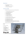
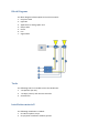
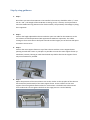
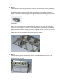
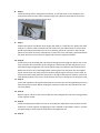
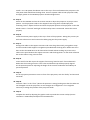
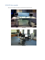
 USER GUIDE AND MANUAL FOR ASSEMBLY iSUW iHTC 3 Dear Customer
We are excited that you chose iSUW iHTC 3. We are confident that you will be satisfied with
your choice during the entire product life cycle. Thanks to the high involvement of users in
the development stage, we have managed to create a product that provides high-use
advantage, and we guarantee that the product has been produced in accordance with quality
standards.
PRODUCER:
iSUW AS
Søren Bulls Vei 29
1051 OSLO
NORWAY
Terje Bakkeli
Managing Director
Tel: + 47 23 17 53 00 / 47 99 47 11 30
E-mail: [email protected]
For service, please contact distributor, or send an e-mail to: [email protected]
Contents Introduction ............................................................................................................................................. 4 Delivery and unpacking ........................................................................................................................... 4 Requirments ............................................................................................................................................ 5 Parts for assembly ................................................................................................................................... 5 Block Diagram .......................................................................................................................................... 6 Tools ........................................................................................................................................................ 6 Installation materiell ............................................................................................................................... 6 Step by step guidance ............................................................................................................................. 7 ISUW IHTC after assembly ..................................................................................................................... 11 Console User manual ............................................................................................................................. 12 Introduction Before use, make sure that the user manual is read thoroughly. The producer is not
responsible for use not in accordance with as described in this user manual.
The console must only be operated by trained personnel. It is important that the personnel
using the device are given a proper training. It is the owner of the product responsibility to
ensure this.
The console has as every device with movable parts some hazard areas. It is important that the
user is aware of these zones, and that the user is sure that there is not any risks involved when
using the advice.
Delivery and unpacking The iSUW iHTC 3 is normally packed in plastic and cartridge, placed on pallets.
The shipment must be checked immediately at arrival. Breakage or faults must be reported to
the shipping company or the producer, and marked on the shipping documents at arrival.
Requirments The standard ISUW IHTC requires: 1. 15 amps 220V. 2. Footprint of 2200 mm by 1600 mm. 3. Min 500 kg/m² floor support. Parts for assembly The iSUW iHTC 3 demo console consists of the following modules: 1. 2 ea height adjustable Columns, picture: 2. 1 ea main support frame, picture: 3. 1 ea curved screen, picture: 4. 1 ea desk top, picture: 5. 2 ea drag chain, picture: 6. 1 ea cable management shelf 7. 2 ea collection box, picture: 8. 2 ea FR12 RLS projector, picture: 9. 1 ea power supply with control panel, picture: 10. 2 ea projector protection leads, picture: 11. 2 ea FR12 RLS light box, picture: 12. 2 ea FR12 RLS LLG (10 m), picture: 13. 2 ea DVI/D cable (10 m), picture: 14. 3 ea power cable (1,5 m) with standard European plug, picture: 15. 1 ea standard European power distribution unit ( 1 to 5), picture: 16. Lot bolts, washers and nuts, picture: Block Diagram The block diagram below explains the interconnections: 1. Projector Head 2. Light Box 3. Application PC with graphic card 4. DVI/D cable 5. Power 6. LLG 7. Signal Cable Tools The following tools are needed to erect the ISUW IHTC: 1. 2 ea Spanner (13 mm). 2. 1 ea Pipe (13 mm) with 150 mm extender. 3. Screwdrivers. Installation materiell The following installation is needed: 1. Lot 100 mm plastic straps 2. Lot projector installation washers/spacers Step by step guidance 1. Step 1 Plan where you want the ISUW IHTC to be installed. The accuracy should be within +/‐ 1ooo mm in x and y. The weight of the ISUW IHTC is 150 kg, hence, it is heavy and unpractical to move the ISUW IHTC long distances after final assembly. The possibility of breakage by doing this is apparent. 2. Step 2 Position the height adjustable Columns inside the space set aside for the iSUW iHTC 3. The two columns should be positioned with approximate 1800 mm separation. The cables coming out from each column shall point inwards and the longest part of the foot shall point toward the screen to be. 3. Step 3 Position the main support frame on top of the Columns with the screen support beams pointing towards the screen. In principle it is possible to mount the main support frame up‐
side down, however, bearing in mind that the desk top shall be fixed to the support frame only one orientation is possible. 4. Step 4 Adjust the positions of the two Columns such as the 4 holes on the top plate of the columns fits the 4 holes (with threads) of the main support frame. Fix the Columns to the main support frame using 4 bolts with washers for each Column. The bolts have to be entered from underneath. Do not tighten the bolts at this stage.(there is a total of 8 bolts) 5. Step 5 Connect the two cables coming out of each Column to the control box (picture), make sure that you place these in the slots marked I and II, and then connect the control box to 220V. By using the operator panel connected to the control box it is now possible to adjust the height of the table to whatever height that might be convenient for working during the rest of the installation. Do not install the Power Supply permanently at this stage. Control box 6. Step 6 Mount the curved screen to the support beams by 4 bolts on each beam, of which 3 bolts have loose nuts and whereas 1 bolt uses a nut welded to the support beam. Start with the bolt that has the welded nut. During this process it might be necessary to move the various parts of the constructions a bit back and forth to make all bolts and nuts to fit. At this point, please tighten all bolts, inclusive those left not tight during step 9. 7. Step 7 Position the two projector heads in their positions which allow the two back feet of the projector head to fit into the purpose prepared holes in the support frame. Please do not fix the projectors at this point. 8. Step 8 Install the 2 drag chains, alongside each column, and fix the chains to the support frame using 2 bolts and nuts each. Also install the drag chain collection boxes but do not fix the collection boxes to the columns at this point. 9.
10.
11.
12.
13.
14.
Step 9 Prepare the LLGs for installation by arranging the cables in 2 separate coils. Make sure these coils get a “natural” radius and please do not enforce any low radius bends as such a bend would most likely permanently ruin the LLG. Likewise, please do not walk on the LLG and please do not place any heavy components on top of the LLGs, and finally, please handle the two ends with extra care as they are fragile and cannot be repaired if broken. Step 10 Install the LLG’s by threading the end without cooling groves through the square hole in the chain collection box and further up the drag chain. Please note that the drag chains has its own cable fixing arrangement that can be opened using a screwdriver and closed by hand. Make care the LLG’s are not damaged when entering from the drag chain into the support frame. Connect the LLG to the projector heads by tightening the nuts firm, but not hard, by hand. At this point make particular attention to the right hand projector head to avoid a too small bending radius of the LLG at the just before the LLG is entered into the projector head. Step 11 Locate the Light Box in their planned position and connect the LLG’s by tightening the nut by hand, firmly but not hard. Before making the connection make sure the LLG does not have any sharp bends. Step 12 Repeat step 11 and 12 for the control cable that runs alongside the LLGs from the light boxes to the projector heads. Step 13 Install the DVI/D signal cables from the PC, providing the application to be presented on the ISUW IHTC, to each projector by applying the same method as described in step 11. Connect the DVI/D plugs to each projector head and to the application PC. Step 14 15.
16.
17.
18.
19.
20.
21.
Install a 1 to 5 AC power distribution unit in the tray in front and between the projectors. The inlet power lead shall follow the drag chain. Connect a power cable to both projector heads, and apply power to the FR12RLS projector heads and light boxes. Step 15 Switch on the FR12RLS and use the remote control to adjust the projectors to project a test pattern. Fix the projector heads to the support frame using the 3 standard projector mounting “holes”. Adjust the focus and then the physical position of the projector so that the whole screen is “covered” with light and the overlap zone is maximized. Fasten the screws properly. Step 16 Install the column power supply in the tray in front of the projectors. During this process you will have to disconnect and connect the cables going into the power supply. Step 17 Arrange the cables in the support structure and in the drag chain neatly, using plastic strips and the standard cable support arrangement provided with the drag chain. Make sure this is done so that the ISUW IHTC can be lowered and raised without making any stress to the cables in the joint between the support structure and the drag chains. Fix the chain collection box to the column using 4 screws each. Step 18 Locate and fix the desk top to the support frame using “wood screws” from underneath. Make sure the screws go into the “old” holes and the desk top will be properly aligned. Fix the operator panel for adjusting the height of the console underneath the tabletop at previous position. Step 19 Fix the 2 projector protection covers in front of the projectors, with the “bulky” end oriented outwards. Step 20 Close the “door” in the “front” (where the operator is sitting) making sure that the cables are not damaged or that the projectors are not brought out of alignment. If so it might be necessary to realign the position of the projector heads. Step 21 Complete the work by adjusting the graphic card to provide the correct overlap (correct resolution is 3520x1200) and adjust the two MIPS units. ISUW IHTC after assembly After correct assembly the ISUW IHTC shall look like the pictures below: Front view Side View Console User manual 1. The iSUW iHTC 3 is electrical height adjustable and can be driven by the operator panel
mounted on the front of the console.
Press
or
.
Press one button until desired height is reached.
Memory function with 4 position-preset keys, extremely flat, LED height-display, output of a
service code.
Note! If the table is skewed, the table can be reset by holding down the down arrow button,
for more than 20 seconds. Button pressed until all actuators are reset. Release the button and
run the re-set function (down arrow) button a second time (in approx. 10-15 sec.).
If the table is still uneven, contact the distributor or supplier.
NOTE! If the table is very skewed, remove the DIN plug (plug is in the transformer / control
unit) belonging to the leg which is the lowest and run the re-setting in the / those legs that are
the highest. When the motor legs are somewhat similar in height, then all plugs inserted in the
transformer / control unit and a re-setting can be performed.
Congratulations! You are now ready to use your iSUW iHTC 3.


![j:j_"Xt$l"j:]:":,lg]:"r/Human Resources have been duty - e](http://vs1.manualzilla.com/store/data/005657435_1-26d97049bf04f0fd92265d73e45a9ab3-150x150.png)