1
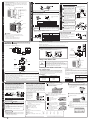
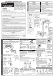
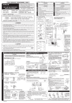
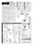
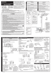
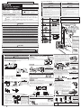
THE CHOICE OF MOUNTING SITE (Please note the following matters and obtain permission from customer before installation).
●
SPLIT UNIT AIR CONDITIONER
INSTALLATION MANUAL
!
Carefully read through the procedures of proper
installation before starting installation work.
The sales agent should inform customers regarding
the correct operation of installation.
Tools Needed For Installation Work
●
Indoor Unit
+ – Screwdriver ● Measuring Tape ● Knife
● Saw ● ø80mm Power Drill ● Hexagonal Wrench
Key ( 4mm) ● Wrench (14, 17, 19, 22, 24, 27mm)
● Gas Leakage Detector
● Pipe Cutter
● Putty
● Pliers
● Vinyl Tape
● Flare Tool
Outdoor Unit
RAS-S18CZT
RAC-S18CZT
SAFETY PRECAUTION
●
●
Read the safety precautions carefully before operating the unit.
The contents of this section are vital to ensure safety. Please pay special attention to the following sign.
WARNING
The unit should be mounted at stable, non-vibratory location which
can provide full support to the unit.
●
No nearby heat source and no obstruction near the air outlet is
allowed.
●
The clearance distances from top, right and left are specified in
figure below.
●
The location must be convenient for water drainage and pipe
connection with the Outdoor unit.
●
To avoid interference from noise please place the unit and its
remote controller at least 1m from the radio, television and inverter
type fluorescent lamp.
●
To avoid any error in signal transmission from the remote controller,
please put the controller far away from high-frequency machines
and high-power wireless systems.
●
The installation height of indoor unit must be 2.3m or more.
CAUTION
Names of Indoor Components
No.
! WARNING ........ Incorrect methods of installation may cause death or serious injury.
!
●
!
INDOOR UNIT
●
Item
OUTDOOR UNIT
FOR SERVICE PERSONNEL ONLY
The Length of Indoor Unit
Connecting Cord
Qty
WARNING
●
The Outdoor unit must be mounted at a location which can support heavy weight. Otherwise, noise and vibration will increase.
●
Do not expose the unit under direct sunshine or rain. Besides, ventilation
must be good and clear of obstruction.
The air blown out of the unit should not point directly to animals or plants.
The clearances of the unit from top, left, right and front are specified in
figure below. At least 3 of the above sides must be open air.
Be sure that the hot air blown out of the unit and noise do not disturb the
neighbourhood.
Do not install at a location where there is flammable gas, steam, oil and
smoke.
The location must be convenient for water drainage.
Place the Outdoor unit and its connecting cord at least 1m away from the
antenna or signal line of television, radio or telephone. This is to avoid
noise interference.
Do not install outdoor unit facing strong wind direction. It may damage the
fan motor.
!
●
●
●
●
●
●
●
CAUTION
Figure showing the Installation of Indoor and
Outdoor Unit.
Hanger
! CAUTION ......... Improper installation may result in serious consequence.
Be sure that the unit operates in proper condition after installation. Explain to customer the proper way of operating
the unit as described in the user’s guide.
! CAUTION
1
1
In case the pipe length is more than 8m, add refrigerant R22 at
15 gram per every meter exceeds. However, pipe length shall
not exceed 20m.
Direction of Piping
Screw for Hanger
!
WARNING
2
(4.1x32)
●
Please request your sales agent or qualified technician to install your unit. Water leakage, short circuit or fire may occur if you
do the installation work yourself.
●
Please observe the instructions stated in the installation manual during the process of installation. Improper installation may
cause water leakage, electric shock and fire.
●
Make sure that the units are mounted at locations which are able to provide full support to the weight of the units. If not, the
units may collapse and impose danger.
●
Observe the rules and regulations of the electrical installation and the methods described in the installation manual when
dealing with the electrical work. Use power cables approved by the authorities of your country.
●
●
Be sure to use the specified piping set for R22. Otherwise, this may result in broken copper pipes or faults.
●
When installing or removing an air conditioner, do not allow air or moisture to remain in the refrigeration cycle. Otherwise,
pressure in the refrigeration cycle may become abnormally high so that a rupture may be caused.
AAA Size Battery
2
4
Screw for holder of
Remote Controller
5
There are 6 directions
allowed, namely, horizontally
perpendicular to the unit,
vertically down from right,
horizontally out from right,
horizontally out to left,
horizontally out to right,
vertically down from left.
Dimension of Mounting Stand
of the Outdoor unit
2
(unit : mm)
6
(3.1x16)
Remote Controller
●
Be sure to ventilate fully if a refrigerant gas leak while at work. If the refrigerant gas comes into contact with fire, a poisonous
gas may occur.
●
After completion of installation work, check to make sure that there is no refrigeration gas leakage. If the refrigerant gas leaks
into the room, coming into contact with fire in the fan-driven heater, space heater, etc., a poisonous gas may occur.
●
Unauthorized modifications to the air conditioner may be dangerous. If a breakdown occurs please call a qualified air conditioner
technician or electrician. Improper repairs may result in water leakage, electric shock and fire, etc.
!
1
3
3
Please use the specified components for installation work. Otherwise, the units may collapse or water leakage, electric shock
and fire may occur.
●
Holder for Remote
Controller
Be sure to use the specified wire for connecting the indoor and outdoor units. Please ensure that the connections are tight
after the conductors of the wire are inserted into the terminals. Improper insertion and loose contact may cause over-heating
and fire.
●
6
The indoor piping should be
insulated with the enclosed
insulation pipe. (If the
insulator is insufficient,
please use commersial
products).
1
6
Purifying Filter
7
●
The difference in height
between the indoor and
outdoor unit should be
kept max 10m.
● The connecting pipe, no
matter big or small,
should all be insulated
with insulation pipe and
then wrapped with vinyl
tape. (The insulator will
deteriorate if it is not
wrapped with tape).
1
CAUTION
A circuit breaker or fuse (20A time delay) must be installed. Without a circuit breaker or fuse the danger of electric shock
exists.
A main switch with a contact gap of more than 3-3.5mm has to be installed in the power supply line to the outdoor unit.
●
Do not install the unit near a location where there is flammable gas. The outdoor unit may
catch fire if flammable gas leaks around it.
●
Please ensure smooth flow of water when installing the drain hose.
●
Piping shall be suitable supported with a maximum spacing of 1m between the supports.
Installation of Hanger, Wall Penetration and Installation of Protection Pipe
1
●
The draining of the water container inside the indoor unit can be done from the left.
Therefore the hanger must be fixed horizontally or slightly tilted towards the side of
drain hose. Otherwise, condensed water may overflow the water container.
2
●
●
●
Connect connecting cord.
Pull out the pipe, connecting cord and drain hose.
Arrange a drain hose in lowest part of a wall hole.
●
●
Please use hidden beams in the wall to hold the hanger.
20mm
External dimension of
indoor unit
141mm
42mm
333mm
42mm
●
●
The upper part of the Indoor unit is hanged on the hanger.
The projection at the lower part of the Indoor unit is hooked onto the hanger.
Layout of pipe
141mm
Layout of pipe
! CAUTION
Drain Hose
1150mm
Please pull the lower part of
the Indoor unit outwards to
check if the unit is hooked
onto the hanger. Improper
installation may cause
vibration and noise.
Level
Hanger
Line
Weight
Mark
Screw for Hanger
Hole for
pipe
HOW TO REMOVE INDOOR UNIT FROM HANGER
Please use more
than 5 screws.
●
Procedures of Installation and Precautions
Procedures to fix the hanger.
1. Drill holes on wall.
2. Push plug into the holes.
(As shown below)
(As shown below)
●
3. Fix the hanger on wall
with 4.1 x 32 screw
(As shown in figure below)
Push up PUSH section on the bottom of indoor
unit, then claws are released from hanger.
(Indicated by 2 arrows in the drawing on the
right.)
●
Holder can be attached at the either of 2 places.
Please select the easier position.
THE CONNECTION OF REFRIGERATING PIPE DURING THE
INSTALLATION OF INDOOR UNIT
Preparation To Install Refrigerating Pipes
! CAUTION
●
●
The refrigerating pipes and connecting cord
transform and are attached.
The end of the refrigerating pipes are at locations
marked with “
” symbol.
Exchange the location of drain hose and drain cap during horizontal piping as shown in
figure below. Be sure to plug in the drain hose until the insulating material folds upon itself.
●
Please use pliers to pull out the drain cap.
(This is an easier way to remove the drain cap).
Procedures to fix the holder of remote control.
1. Drill holes on wall.
2. Push plug into the holes.
(As shown below)
(As shown below)
●
Drain cap
Drain hose
Installation
Connecting
cord
Wall Penetration and Installation of Protection Pipe
●
●
<IA655: A >
Please fix in the plastic core
after flaring to avoid plastic
chips entering the pipes.
Hang the Indoor unit onto the hanger. Use the temporary stand
at the back of the Indoor unit to push its lower part 15cm
forwards.
● Place the drain hose through the hole on the wall.
● Wrap the refrigerating pipes with insulation pipe after
connecting refrigerating pipe.
● Connect the connecting cord after removing electrical cover.
(Refer to “Connection of Power Cord”)
● After adjustment, the connecting cord and refrigerating pipes
are placed into the space available under the Indoor unit.
Use holder to hold them tight.
● The projection of Indoor unit must hook to the hanger.
Heat insulation pipe
Pull this to the front
during the connection
of refrigerating pipes
to ease task.
Refrigerating pipe
! WARNING
Be sure that the wire is not
in contact with any metal
in the wall. Please use the
protection pipe as wire
passing through the hollow
part of the wall so as to
prevent the possibility of
damaged by mouse.
Unless it seals completely,
any air with high humidity
flows from outdoor and
any dew may drop.
●
Preparation
●
Drill a ø 80mm hole on
wall which is slightly tilted
towards the outdoor side.
Drill the wall at a small
angle.
Cut the protection pipe
according to the wall
thickness.
Empty gap in the sleeve
of protection pipe should
be completely sealed
with putty to avoid
dripping of rain water into
the room.
The rubber strap used for
fixing the insulator should
not be tied with great force.
Otherwise, this will damage
heat insulation and causes
water condensation.
HORIZONTAL PIPING
Change of Drain Hose and Installation Procedures.
●
! CAUTION
Installation
93mm
58mm
The refrigerating pipes should be adjusted to fit into
the hole on the wall and then ready for further
connection.
The terminals of 2 connected pipes must be covered
with insulator used for terminal connection. Then the
pipes are wrapped with insulation pipe.
Connect the connecting cord after removing electrical
cover. (Refer to “CONNECTION OF POWER CORD”)
After adjustment, fit the connecting cord and pipes
into the space available under the indoor unit. Use
holder to hold them tight.
●
40mm
INDOOR UNIT
INSTALLATION OF REFRIGERATING PIPES AFTER CONNECTION
Installation of the Indoor Unit
Preparation
●
●
Direct Mounting On The Wall
●
Please use insulated drain
hose for the indoor piping
(commercial product).
DIRECTLY BACKWARD AND DOWNWARD PIPING
! CAUTION
The connection of insulated
drain hose.
700
! CAUTION
Condensed water may leak out if not inserted properly.
3
Installation of Drain Hose
HORIZONTAL & DOWNWARD PIPING – MAKING OPENINGS
●
! CAUTION
During horizontal or downward piping, use a knife to cut
openings as shown in figure. Then smoothen the edges of
openings with a file.
●
Turn the piping while holding down the lower
portion of pipe-support by hand.
Be sure that the
drain hose is not
loosely connected
or bend.
You are free to choose the side (left or right) for the installation of drain
hose. Please ensure the smooth flow of condensed water of the Indoor
CAUTION unit during installation. (Carelessness may result in water leakage.)
!
●
Top cover
1
INSTALLATION OF REFRIGERATING PIPES AND AIR REMOVAL
●
Please face this side (suction
side) of the unit to the wall.
➤
Please remove side cover
when connecting the piping
and connecting cord.
OUTDOOR UNIT
➤
Cabinet
➤
➤
Pull downward
Side cover
Back cover
Top cover
Cabinet
Back cover
Side cover
! CAUTION
Please make sure to remove all spacers inside the unit.
● Open the Top, Back, Side cover and Cabinet of the unit.
● Pull out the spacers inside.
(Spacers are only for transportation purpose).
If not remove, vibration and noise will occur.
! WARNING
●
●
3
Preparation of Pipe
Removal Of Air From The Pipe And Gas Leakage Inspection
Use a pipe cutter to cut the copper pipe.
Procedures of using Vacuum Pump for Air Removal
1
! CAUTION
●
Jagged edge will cause leakage.
Point the side to be trimmed downwards during trimming to prevent copper
chips from entering the pipe.
●
Before flaring, please put on the flare nut.
●
●
Outer
Diameter (mm)
2
●
Please use exclusive
tool
A (mm)
Rigid flaring tool
Imperial flaring tool
6.35
0.8
12.7
1.0
~
~
1.5mm
0
2.0mm
0
~
~
2
3
0.5mm
1.0mm
Pipe Connection
! CAUTION
●
AIR REMOVAL
Please mount the Outdoor unit on stable ground to prevent vibration
and increase of noise level.
Decide the location for piping after sorting out the different types of
pipe available.
When removing side cover, please pull the handle after undoing the
hook by pulling it downward.
●
4
In case of removing flare nut of an Indoor unit, first remove a nut
of small diameter side, or a seal cap of big diameter side will fly
out. Prevent water from entering into the piping when working.
Please be careful when bending the copper pipe.
Screw in manually while adjusting the center. After that, use of torque wrench to
tighten the connection.
THIS APPLIANCE MUST BE EARTHED.
Torque N·m
(kgf · cm)
Small dia. side
6.35 (1/4")
13.7 – 18.6 (140 – 190)
Large dia. side
12.7 (1/2")
44.1 – 53.9 (450 – 550)
Small dia. side
Valve
head cap Large dia. side
6.35 (1/4")
19.0 – 21.0 (194 ~ 214)
12.7 (1/2")
24.0 – 26.0 (245 ~ 265)
Meter showing pressure
Closed
Valve
Manifold valve
Charge hose
Vacuum
pump
Valve
Vacuum pump
adapter
Fully tighten the “Hi” shuttle of the
manifold valve and completely
unscrew the “Lo” shuttle. Run the
vacuum pump for about 10–15
minutes, then completely tighten
the “Lo” shuttle and switch off the
vacuum pump.
When pumping starts, slightly loosen the
flare nut to check of air sucked in. Then
tighten the flare nut.
Completely unscrew the spindle of
the service valve (at 2 places) in
anti-clockwise direction to allow the
flow of coolant (using Hexagonal
Wrench key).
Remove the charge hose and
tighten the cap of valve head.
Check the cap’s periphery if there
is any gas leakage. The task is
then completed.
Gas Leakage Inspection
Please use gas leakage detector to check if
leakage occurs at the connection of Flare nut
as shown on the right.
If gas leakage occurs, further tighten the
connection to stop leakage.
9.0 (92)
Valve core cap
Wiring Of The Indoor Unit
For wire connection of the Indoor unit, you need to remove front panel and electrical cover.
●
Procedures of Wiring
Outer
dia.of pipe
When the meter reaches - 101KPa
(-76cmHg) during pumping, fully
tighten the shuttle.
As shown in right figure, remove
the cap of valve core. Then,
connect the charge hose. Remove
the cap of valve head. Connect the
vacuum pump adapter to the
vacuum pump and connect the
charge hose to the adapter.
Method to remove front panel
● Refer to “FINAL STAGE OF INSTALLATION – How to Remove The Front Cover”.
In case that power is supplied from Indoor Unit
Method to remove electrical cover
●
●
CONNECTION OF POWER CORD
●
Connect the
earth cord
Connecting Cord
After remove the screw
and band, put the
connecting cords and fix
the band with screw.
Connecting Cord
Screw
Screw
Electrical cover
Wiring of The Outdoor Unit
Indoor
Unit
●
A B
Please remove the side cover for wire connection.
Earth terminal
GRN + YEL
●
!
Strip wires
●
WARNING
●
Outdoor
Unit
●
●
The naked part of the wire core should be 10 mm and fix it to the terminal tightly. Then try to pull the
individual wire to check if the contact is tight. Improper insertion may burn the terminal.
●
Be sure to use only power cables approved from the authorities in your country. For example in Germany:
Cable type: NYM 3x1.5mm2, (fuse = 20A time delay)
●
Please refer to the installation manual for wire connection to the terminals of the units. The cabling must
meet the standards of electrical installation.
●
●
●
●
The connected terminals should be completely sealed with
heat insulator and then tied up with rubber strap.
Please tie the pipe and power line together with vinyl tape as
shown in the figure showing the installation of Indoor and
Outdoor units. Then fix their position with holders.
To enchance the heat insulation and to prevent water
condensation, please cover the outdoor part of the drain hose
and pipe with insulation pipe.
Completely seal any gap with putty.
3
Before installation, the power source must be checked and necessary
wiring work must be completed. To make the wiring capacity proper, use
the wire gauges list below for the lead-in from a pole transformer and for
the wiring from a switch board of fuse box to the main switch and outdoor
unit in consideration of the locked rotor current.
IMPORTANT
Cable length
There is a AC voltage of 220V between the L and N terminals. Therefore, before servicing, be sure to
remove the plug from the AC outlet or switch off the main switch.
1 Insulation And Maintenance Of Pipe Connection
●
2
●
●
1.5mm
2.5mm2
up to 25m
4.0mm2
The controller must
be hooked onto the
hook at the lower
part of the holder.
Push in the remote
controller in the
direction as shown
in figure below.
Power Source
! CAUTION
Please use a new socket. Accident may occur due to
the use of old socket because of poor contact.
Please plug in and then remove the plug for 2 – 3 times.
This is to ensure that the plug is completely plugged into
the socket.
Keep additional length for the power cord and do not
render the plug under external force as this may cause
poor contact.
Do not fix the power cord with U-shape nail.
●
●
●
Operation Test
●
●
Please ensure that the air conditioner is in normal operating
condition during the operation test.
Explain to your customer the proper operation procedures
as described in the user’s manual.
<IA655: A >
●
How to check pipe bending.
– Compare bended pipe with the picture below.
– If bended pipe is not good enough, cut bended area and
bend it again.
a
all areas are smooth, no notching area
b
no scratch or mark inside
c
all have the same length
d
phase of bending is too long
e
slanting
f
there are scratches around bending area
g
crack
h
different length
i
sample of bending pipe cannot be used
Investigate the power supply capacity and other electrical conditions at
the installation location.
Depending on the model of room air conditioner to be installed, request
the customer to make arrangements for the necessary electrical work
etc.
The electrical work includes the wiring work up the outdoor. In localities
where electrical conditions are poor, use of a voltage regulation is
recommended.
! CAUTION
2
up to 16m
Installation Of Remote Controller
●
Wire cross-section
up to 15m
The remote controller can be placed in its holder which is
fixed on wall or beam.
To operate the remote controller at its holder, please ensure
that the unit can receive signal transmitted from the controller
at the place where the holder is to be fixed. The unit will beep
when signal is received from the remote controller. The signal
transmission is weaken by the fluorescent light. Therefore,
during the installation of the remote control holder, please
switch on the light, even during day time, to determine the
mounting location of the holder.
Power Source And Operation Test
●
If you cannot attach the side cover due to the connecting cord, press
the connecting cord in direction to the front panel to fix it.
Be sure that the hooks of the side cover is fixed in certainly. Otherwise
water leakage may occur and this causes short circuit or faults.
The connecting cord should not touch to service valve and pipes. (It
becomes high temperature in heating operation.)
Checking for the electric source and
the voltage range
GRN + YEL
! WARNING
FINAL STAGE OF INSTALLATION
Remove the screw and electrical cover.
Insert the connecting cord (A, B) from the bottom of unit.
Fixed the wire to terminal wires firmly as shown in figure at right side.
IMPORTANT
Fuse Capacity
20A time delay fuse
How to Remove The Front Cover
1
How to Attach the Front Cover
Open the front panel.
●
Please remove and attach the
front panel by both hands.
●
After opening the front panel by both hands.
Undo the right arm while pushing it inside.
Slide the front panel to right as shown in figure. Then
remove while pulling it to front.
1
2
Note:
● Outdoor supply cords shall not be
lighter than polychloroprene
sheathed flexible cord with code
designation 60245 IEC 57.
1
After covering the front cover to the unit, certainly hook at
the upper portion (four places). Then, check that the drain
pan is certainly attached. Push the front cover in the
direction of arrow at the
portion of hooks.
2
Hook the front cover at lower portion to the drain pan and
then fix them by screws and attach the caps.
3
Attach the front panel.
Hole
Shaft
2 Remove the filters.
Cap
3 Remove the caps and screws
at the lower portion of the
front cover.
Screw
Guide
●
4 Pull the front cover upward as far
as the location where the lower
portion of the front cover is on
the deflector.
Lower
5 Remove while pulling the front
cover in direction to arrow as
shown in figure to hold the both
sides of front cover.
portion of front cover
Deflector
4
●
Certainly insert the left shaft of the front panel to the hole
of the front cover. Next insert the right shaft as same as
the left.
Attach the filters which are placed the surface written
“FRONT” up.
After attaching the filters, push the front panel at three
arrow portion as shown in figure and close it.