1
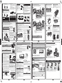
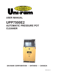
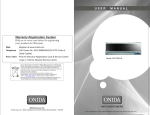
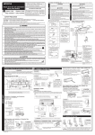
RAS-SX10HYK_EN_1.ai 2010-7-7 11:51:19 FOR SERVICE PERSONNEL ONLY Backward piping HITACHI SPLIT UNIT AIR CONDITIONER INSTALLATION MANUAL INDOOR UNIT / OUTDOOR UNIT Remove the auxiliary insulation material sheet which is attached to the pipe insulation. Referring to the mark on the rear side, form the pipe within the wall hole range. No nearby heat source and no obstruction near the air outlet is allowed. The air blown out of the unit should not point directly to animals or plants. Place the starting point of refrigerating pipe bending within the wall hole range. RAS-18SH2/RAC-18SH2 • Be sure to perform the cleaning unit operation check. • Unlike conventional types, this model has no grille on its top surface. SAFETY PRECAUTION If the starting point of refrigerating pipe bending is projected from the wall hole range or if the bending radius is too large, the indoor unit may be lifted from wall and this may cause poor finishing. The installation height should be at least 2.3m or more from the floor. Pipe Layout of horizontally piping from the right Temporarily join the refrigerating pipe, drain hose and connecting cord with tape. Qty Figure showing the installation of Indoor and Outdoor Unit (For example: Ground installation) Mounting board Above 50mm (Above 100mm when there is piping connection at the back of the outdoor unit) 24mm Supplied Items If the starting point of refrigerating pipe bending is projected from the wall hole range or if the bending radius is too large, the indoor unit may be lifted from wall and this may cause poor finishing. • Transform the piping while holding down the lower portion of pipe-support by hand. 5 3 Anti-mold wasabi cassette Heat insulating materials 2.3m or more The indoor piping should be insulated with the enclosed insulation pipe. Above 50 mm when installed on the ceiling of balcony • The difference in height between the indoor and outdoor unit should be kept below 10m. • The connecting pipe, no matter big or small, should all be insulated with insulation pipe and then wrapped with vinyl tape. The insulator will deteriorate if it is not wrapped with tape. Above 50mm give clearance as widely as possible Above 200mm Drain pipe Connection of insulated drain hose Please use insulated drain hose Inner diameter 16mm for the indoor piping (commercial product). Above 100mm Above 200mm Nano titanium air cleaning mesh Heating efficiency will be enhanced if the space below the outdoor unit is closed so that no air passes through. (Procure the material locally.) Items 8 & 9 are included in the package of the outdoor unit. For details on installing Component 0 (namely the nano titanium air cleaning mesh), refer to pages 5 and 53 in the Operating Instructions. Temporarily join the refrigerating pipe, drain hose and connecting cord together with tape. Temporarily join the refrigerating pipe, drain hose and connecting cord together with tape. About 1.6m Pipe Installation after connection of refrigerating pipes (Horizontal piping) Remove the auxiliary insulation material sheet which is attached to the pipe insulation. Connect the refrigerating pipe. (Refer to “Pipe Connection” on page 9) Cut the heat insulation sheet refrigerating pipe aligning to the insulation sheet of the pipe and fix them temporarily with tape. Cover the pipe connection with the auxiliary insulation sheet which was removed earlier, with its split line on the top. Wrap the tape without any gap. Tape must not be over tightened. (Refer to “Heat insulation and Finishing of Piping” on page 11) If there is gap or over-tightened, it may cause condensation. Connecting cord Place the refrigerating pipe bending within the wall hole range Drain hose Drain hose Cut Join refrigerating pipe, connecting cord and drain hose temporarily with tape and wrap the wall hole portion with tape. Binding band About 90mm Temporarily wrap with tape Split line of the auxiliary insulation sheet must be positioned within this range. Wrap with tape M Auxiliary insulation sheet CAUTION Connecting the refrigerating pipe other than at the back of the indoor unit 6 Refrigerating pipe Horizontally backward C Please bend at a small radius to form an arc. (Pipe can be bent with a small radius without being crushed if a plastic hose is used.) 2.2 Installation Refrigerating pipe Form the connecting cord and refrigerating pipe and put them in the space on the lower side of the rear surface of the indoor unit. Put the binding band on the hook located on the rear surface to fix it. Refrigerating pipe Auxiliary insulation sheet Refrigerating pipe insulation sheet Piping configuration may be in six different directions: direct rear piping, left or right downward piping and left or right sideways piping. Insert a plastic hose (commercial product) into the large diameter pipe. • When using a plastic hose, make sure to insert it only after pipe expanding is carried out to avoid cutting dust from getting inside. 5 Refrigerating pipe Refrigerating pipe insulation sheet Drain hose Refrigerating pipe Center line of wall hole ø65 wall hole range Center line of wall hole Pipe support Direction of Piping Do not modify the power cable. ø65 wall hole range Transform after bending downward Pipe support Wrap the wall hole portion with tape. For outdoor unit installation, allow at least 2 sides of space around the unit to ensure ventilation flue. Length of Power Cable About 0.9m Auxiliary insulation sheet The refrigerating machine oil is easily affected by moisture. Use caution to prevent water from entering the cycle. Above 200mm Bush Above 80mm When installing the indoor unit above the curtain rail or curtain box, allow dimensions not affecting the airflow. Drain hose 24mm Remote controller Place the ending point of refrigerating pipe bending within this range. 36~41mm Screw for remote controller holder Above 50mm Must not bend About 0.45m AAA size battery About 300mm The space indicated by an arrow Á is to guarantee the performance of the air conditioner. Install the apparatus at the ample space in order to carry out the maintenance and repair works. Maximum pipe length 20m Screw for mounting board Above 50mm 56.5mm Be sure to completely seal any gap with putty. Large diameter 1.00m (2) When forming, bend the refrigerating pipe with the smallest radius. ø65 wall hole range 41mm Small diameter Below 5mm Refrigerating pipe Place the refrigerating pipe bending within the wall hole range Match the end of the refrigerating pipes with the locations marked with “V” symbol. CAUTION Center line of wall hole 36mm 2 1 • Form and set the refrigerating pipe and connecting cord. Place the starting point of refrigerating pipe bending within the wall hole range. Pipe support No. Connecting the refrigerating pipe at the back of the indoor unit Please bend at a small radius to form an arc. Pipe support 36~41mm • Read the safety precautions carefully before operating the unit. • The contents of this section are vital to ensure safety. Please pay special attention to the following sign. WARNING ...... Incorrect methods of installation may cause death or serious injury. This sign indicates prohibition. CAUTION ....... Improper installation may result in serious consequence. Be sure that the unit operates in proper condition after installation. Explain to customer the proper operation and maintenance of the unit as described in the user’s guide. Ask customers to keep this installation manual together with the instruction manual. Bottom cover bush hole Forming of refrigerating pipe for horizontally backward piping (1) Refer to the mark at the back, start bending the refrigerating piping within wall hole range. Drain hose 56.5mm information Installation Remove the auxiliary insulation material sheet which is attached to the pipe insulation. (Keep the removed auxiliary insulation material sheet because it will be reused after pipe connection.) Carry out refrigerating pipe forming. Wall hole range Please bend at a small radius to form an arc. Do not install at a location where there is flammable gas, steam, oil and smoke. Form the refrigerating pipe according to the wall hole position. Especially in the case of horizontally backward piping, follow the instruction below to carry out accurate forming. Horizontally and downward piping from the right Preparation of Pipe • Carefully read through the procedures of proper installation before starting installation work. • The sales agent should inform customers regarding the correct operation of installation. Insert the pipes through the wall hole. Hang the upper part of the i ndoor unit on the mounting board. Push the lower part of the indoor unit to the wall, hook the projection on the lower part of the indoor unit onto the mounting board. Cover the pipe connection with the auxiliary insulation sheet which was removed earlier, with its split line on the top. Wrap the tape without any gap. (Refer to “Heat insulation and Finishing of Piping” on page 11) If there is gap or over-tightened, it may cause condensation. Mounting board Refrigerating pipe Protection pipe Binding band can be installed to whichever side of the installation points. However, it is recommended to attach it on the right side viewing from the rear. Drain hose Hook Wrap with tape Mounting board Be sure to cut the extra binding band. (Otherwise, it may result in abnormal noise or dewfall.) Pipe Connecting cord Projection of the indoor unit Y CM MY CY Outdoor water outlet 2. Installation of the Indoor Unit 2.1 Preparation of Installation Changing of drain hose (Horizontally piping) Remove the front panel • To remove front panel, please refer to “Removing and • Install and change the drain hose and drain cap when installing Attaching the Front Panel” on page 13. the pipe horizontally as shown below. • Make sure to use both hands to attach and remove the front • Remove the lower cover when installing and changing. panel. • Do not carry out horizontal piping for drain hose. Remove the lower cover • Push the bottom inner part (1 ) of the lower cover to remove the lower cover. on Leveler Screw fixing the mounting board Board anchor 1 2 Auxiliary insulation sheet 1 Remove the screw and pull out the drain hose. Drain hose Wiring connection Pull this to the front during the connection of refrigerating pipe to ease task. Connection part Connecting cord • Please refer to “Connection of Power Cord” on page 10. 58mm 295mm 80mm 200mm 600mm 42.5mm 80mm Auxiliary insulation sheet • While installing the pipe from the right, left or bottom side, use a knife to cut lower cover bush accordingly. • Use the groove on the outer side if the pipe which is to be installed from the left side, etc. is big. 100mm 52mm 798mm 450mm 450mm 175mm Cutting lower cover bush (Horizontal and downward piping) Drain hose screw Drain cap 2 Insert drain cap up to the location securely till the cap stops. Push the drain hose deeply into the screw hole, fix with the removed screw during step 1. Drain hose CAUTION 350mm 638mm Bush part Groove on the Bush part outer side Groove on the inner side • Be sure to insert drain hose and drain cap firmly and fix with screw Insufficient insert may result in water leakage. Refrigerating pipe Connecting cord CAUTION • Do not over tighten vinyl tape on pipe heat insulation sheet Do not over tighten to avoid loss of heat insulating effect and dew condensation. • Pull the lower part of the indoor unit towards you and confirm that the tab of the indoor unit is fit in the installation plate If the tab is not fitted in securely, vibration of the indoor unit becomes stronger. CAUTION • During drainage work, install the drain pipe to ensure smooth drainage. Make sure to carry out drainage check. Careless work may result in water leakage. • Make sure that there is no problem as shown in the figures on page 8. Such problems may cause clogged drain and could result in water leakage. • Drain hose must be at a slope of at least 1/25. • When inserting the drain hose into the drain pipe for embedded piping, etc., do not cut the drain hose in the middle. This may lead to poorer heat insulating performance of the drain hose and could result in water leakage. • Do not lead the drain hose to a place where corrosive gas (sulfur, ammonia, etc.) is generated such as septic tank. Corrosive gas may flow into the indoor unit through the drain hose, and could result in corrosion on the copper pipe and odor in the room. Fixed leg dimension of outdoor unit In snowy region, install a snow guard and elevated stand to ensure the airflow for better heating efficiency. In other regions, it is recommended to install a tent for shade. Tent 12 Dimensions of indoor unit Please remove side cover when connecting the piping and connecting cord. Claw After the indoor unit is installed, please ensure the smooth flow of condensed water of the indoor unit during installation. (Careless work may result in water leakage.) Drain hose screw Attach Please face this side (suction side) of the unit to the wall. Mounting board 3. Drainage Check Drain hose 1 Condensed water pond Ditch Screwdriver Protection pipe Weight Pipe hole You are free to choose the side (left or right) for the installation of drain hose. Please ensure the smooth flow of condensed water of the indoor unit during installation. (Careless may result in water leakage.) Pull downward Use the plier to pull and turn the drain cap for easy removal. • To attach the lower cover, attach 2 first and then attach 1 by rotating it around 2 as the fulcrum. Line CAUTION • Please mount the outdoor unit on stable ground to prevent vibration and increase of noise level. • Decide the location for piping after sorting out the different types of pipe available. • When removing side cover, please pull the handle after undoing the hook by pulling it downward. Reinstall the side cover in reverse order of the removal. Hold with hand Be sure that the drain hose is loosely connected bend or proper condition like left figure. Drain hose Drain hose Remove Mounting board Mark Condensed water pond Bending upwards Hole for removal Hole for removal Drain cap CAUTION 299 9 Remove the auxiliary Projection Cushion insulation material sheet of the which is attached to the indoor unit Fixing pipe insulation. (Keep tab the removed auxiliary insulation material sheet About 15cm because it will be reused after pipe connection.) Hang the indoor unit on the mounting board. Place the cushion under the right rear surface of the indoor unit to lift the lower side of the unit by approximately 15cm. Connect the refrigerating pipe. (Refer to “Pipe Connection” on page 9) Cover the pipe connection with the auxiliary insulation sheet which was removed earlier, with its split line on the top. Wrap the tape without any gap. (Refer to “Installation after connection of refrigerating pipes (Horizontal piping)” on page 5, step 3 ) Insert the drain hose into the wall hole. Connect the connecting cord. (Refer to “Connection of Power Cord” on page 10). Form connecting cord and refrigerating pipe and put them in the space on the lower side of the rear surface of the indoor unit. Remove the temporary stand and hook the projection on the lower part of the indoor unit onto the mounting board. 330 Press it into the hole in the chassis • Protection pipe (commercial product) must be used Be sure that the wire is not in contact with any metal in the wall. Please use the protection pipe as wire passing through the hollow part of the wall to prevent damaged by mouse, possibility of short circuit or fire. • Completely seal with putty High humidity air inside the wall or the outdoor may go in to the room and could result in dripping of dew. It could also cause smell or odor present outdoor and inside the wall spreading into the room. How to remove the indoor unit • Push the [PUSH] section at the bottom of the indoor unit from the outside, the claws are released from the mounting board. (2 places on the left and right) • If the bottom of the indoor unit cannot be pushed, remove the bottom part of the front cover and insert a screwdriver into the hole for removal of indoor unit as shown in the figure. Then, push the claws upwards while holding down the upper part of the hole 1 and pull the indoor unit towards you 2. When horizontal piping is used, be careful not to damage the pipe and connecting cord with the tip of the screwdriver during this operation. • Please refer to “Removing and Attaching the Front Cover” on page 14 to remove the bottom part of the front cover. 310 Press it into the hole in the chassis Connecting the refrigerating pipe at the back of the indoor unit WARNING OUTDOOR UNIT Press it into the hole in the chassis K 1.2 Wall Penetration and Installation of Protection Pipe Drill a ø65mm hole on wall which is slightly tilted towards Indoor WALL Outdoor the outdoor side. Putty Putty Cut the protection pipe according to the wall thickness and pass through the wall hole. Empty gap in the sleeve of Protection Sleeve of protection pipe should be pipe protection completely sealed with putty pipe to avoid dripping of rain water into the room. 2~5mm CMY 500 792 CAUTION • Do not touch the suction port, bottom surface or aluminium fin of the outdoor unit. Failure to do so may cause an injury. Elevated stand RAS-SX10HYK_EN_2.ai 2010-10-14 16:46:21 2. Pipe Connection • Remove the flare nut from the pipe of the indoor • Use a pipe cutter to cut the pipe and remove burr. unit by removing the flare nut (female side) with a spanner while holding down the half union (male side) with a spanner. • Do not crush the pipe while bending it. • Apply refrigerant oil on the connection part. After carrying out the center alignment and manual tightening of the flare nut, tighten the flare nut securely with a torque wrench (spanner). Trimming tool Copper pipe • Remove burr If burr is not removed, it may cause leakage. • Point the side to be trimmed downwards during trimming to prevent copper chips from entering the pipe. Male side Die Procedures of Wiring A Detail of Cutting the Connecting Cord * Tightening torque must be as shown in the table below. Indoor unit Copper pipe Outer diameter of pipe (ø) Torque N•m (kgf•cm) Small diameter side 6.35 (1/4 ”) 13.7~18.6 (140~190) Large diameter side 12.7 (1/2 ”) 44.1~53.9 (450~550) Valve head cap Small diameter side 6.35 (1/4 ”) 19.6~24.5 (200~250) Large diameter side 12.7 (1/2 ”) 29.4~34.3 (300~356) Please use exclusive tool for refrigerant R410. A (mm) Rigid Flaring Tool For R410A tool For R22 tool 6.35 (1/4 ”) 0~0.5 1.0 12.7 (1/2 ”) 0~0.5 1.0 Valve core cap 3. Remove of Air from the Pipe and Gas Leakage Inspection 2 • Fully tighten the “Hi” shuttle of the manifold valve and completely unscrew the “Lo” shuttle. Run the vacuum pump. (Adapter is switched on) • After pumping for about 10-15 minutes, completely loosen the “Lo” shuttle and switch off the vacuum pump. (Adapter is switched off) Meter showing pressure Make sure the meter reaches -0.1MPa Closed (-76cmHg) during pumping. 1 3 R410A Manifold valve Valve Vacuum pump Ball valve 4 Charge hose Vacuum pump adapter C Please leave the ball valve fully open at all times. Ball valve Outdoor unit 70mm 10mm A Strip wires A B C A B C Connecting cord • Outdoor unit 160mm 10mm 70mm Strip wires 10mm B Connecting cord • Remove the valve head cap of the service valve. • Remove the cap of valve core and connect the charge hose. • Connect the vacuum pump adapter to the vacuum pump and connect the charge hose to the adapter. Valve head cap for the service valve at small diameter side Valve head cap for the service valve at large diameter side Cap of valve core • Loosen the spindle of the service valve with small diameter by 1/4 turn and tighten the spindle immediately after 5 to 6 seconds. • Remove the charging hose from the service valve. • Unscrew the spindle of both the service valves in anticlockwise direction to allow the flow of refrigerant (unscrew halfway). • Tighten the cap of valve head. Check and make sure that there is no gas leakage. Green + Yellow 20mm 100mm WARNING • If the supply cord is damaged, it must be replaced by a special cord (Maker’s service parts) available from the manufacturer or its service agent. • The naked part of the wire core should be 10mm fix it to the terminal tightly. Then try to pull the individual wire to check if the contact is tight. Improper insertion may burn the terminal. • Be sure to use only wire specified for the use of air-conditioner. • Be sure to use only power cables approved form the authorities in your country. For example in Germany: Cable type: NYM • • • • 3×2.5mm2. (Fuse = 16A time delay) Please refer to the manual for wire connection, the wiring technique should meet the standard of the electrical installation. Leave some space in the connecting cord for maintenance purpose and be sure to secure it with the cord band. Secure the connecting cord along the coated part of the wire using the cord band. Do not exert pressure on the wire as this may cause overheating or fire. There is a AC voltege of 220V between the A and B terminals. Therefore, before servicing, be sure to remove the plug from the AC outlet. Wiring of the Indoor Unit Remove the front panel. (Refer to “Removing and Attaching the Front Panel” on page 13) Remove the terminal cover and screw, hold the upper part when removing. Screw Terminal cover Body of service valve Lower cover Cap of valve core Hexagonal wrench key Cap of valve head Connecting cord 45mm 160mm 10mm C Strip wires A ø2.0 ᤋ ଋ ႂ ጲ ᄉ ଋ ፝ Green + Yellow (ground) 10mm C B • When removing flare nut of the indoor unit, first remove the nut of small diameter side. Otherwise the nut of big diameter side will fly out. • Prevent water from entering into the piping when connecting. • Be sure to tighten the flare nut to the specified torque with a torque wrench. If the flare nut is overtightened, it may split after sometime and may cause refrigerant leak. • When using a control valve, make sure that the packing is not deteriorated and avoid excessive tightening of the handle. Otherwise, gas may leak from the service valve. From the viewpoint of global environment protection, air purge type should be vacuum pump method. • Indoor unit AC 220V 1ø 50Hz 12.3~15.7 (125~160) CAUTION When pumping starts, slightly loosen the flare nut to check if air sucked in. Then tighten the flare nut. M Torque wrench Bring the connecting cord from the rear surface to the front surface through the cable guide. The connecting cord should be fix with the terminal. Tightening torque reference value: 1.2~1.6N•m (12~16kgf•cm) Excessive tightening may damage the terminal. Refrigerating pipe Removing Screw Terminal block cover Fix on the top tabs (2 places) Move Screw cover Screw Arm Terminal block cover Arm Unscrew screws of the terminal block cover, and remove the terminal block. Remove the screw cover below the panel frame, and unscrew the 7 screws from the panel frame. Tighten the 7 screws in the panel. Install the terminal block cover, and tighten the screws. Install the screw cover. Push the end of the right-side arm outward to release the tab. Move the left-side arm outward to release the left tab, and then pull the panel towards you. Screw Screw Terminal block cover Attaching front panel Terminal block cover Insert ᦦܹ Insert Screw cover Screw Install the storage box and the panel. Insert the screw driver into the hole on the right upper part of the panel frame, and loosen the jaw. H-LINK [For details on part numbers of optional accessories, refer to the catalogue.] Arm Arm Step To connect to H-LINK, purchase a RAC adaptor separately. Step • When connecting wires, be sure to open the electric box cover. • Connect the socket of RAC adaptor to CN7. • Reattach the electric box cover. • For details on the RAC adaptor, refer to its user manual. • Please take care when connecting the optional adaptor to prevent the edge of the circuit board from cutting the lead wire. • Remove and install the front cover by referring to this Instruction Manual. Hold the panel frame and pull it along the direction indicated by the arrow to remove it. Insert the shaft of the left arm along the step on the unit into the hole. Securely insert the shaft of the right arm along the step on the unit into the hole. Make sure that the front panel is securely attached, and then close the front panel. Drain hose CN7 $ Connecting cord CN7 CAUTION When being installed or removed, the panel is likely to slide off. % Connect the connecting cord and fix with cord band. Remove the lower cover. Screw Screw storage box Cable guide Connecting cord Make sure that the dew receiving pan and the cleaning unit are securely attached. After attaching the left and right sides of the front cover onto the unit, ensure that the top tabs (2 places) have been fixed on. Remove the front panel and the storage box. Please refer to the operation manual on how to open and close the front panel. front panel Die Outer Diameter (ø) • Be sure to hold the front panel with both hands to detach and attach it. Female side Wrench Attaching the Front Cover How to remove the panel frame Removing and Attaching the Front Panel From the viewpoint of global environment protection, refrigerant should be recovered (pumped down) when the air conditioner is transferred or removed. Perform force-cooling operation (refer to “Force-cooling operation” on page 12) for about 5 minutes as a preliminary operation. Tighten the spindle of the service valve at small diameter side in clockwise direction. Continue the force-cooling operation for another 1-2 minutes, and then tighten the spindle of the service valve at large diameter side in clockwise direction. Stop the force-cooling operation. Flare nut Half union • Before flaring, please put on the flare nut. Please use gas leakage detector to check if leakage occurs at connection of Flare nut as shown on the right. If gas leakage occurs, further tighten the connection to stop leakage. (Be sure to use R410A detector.) CONNECTION OF POWER CORD INSTALLATION OF REFRIGERATING PIPES AND AIR REMOVAL CAUTION Works to be done when transferring or removing air conditioner Gas Leakage Inspection REMOVING AND ATTACHING THE FRONT COVER 1. Pipe Cutting and Flaring When lifting to open the panel, do not apply too much force. Otherwise, the panel may come off or malfunction may be caused. Cord band & Hook onto the claw at the lower part of the terminal cover and fix with screw. Cap of valve head Y CM MY CY CAUTION About Address Selector Switch Terminal cover Please remove the side cover and terminal cover for wiring connection. WARNING • The connecting cord must be fix with cord band Otherwise rain water may enter and cause short circuit. Besides, an external force may apply to the connection part of the connecting cord and could result in heat and fire. • The terminal cover and side cover must be installed after work is done. Cord band IMPORTANT CAUTION Fuse Capacity • Outdoor supply cords shall not be lighter than polychloroprene sheathed flexible cord with code designation 60245 IEC 57. How to check Micro Mesh Stainless Filter installation • Before trial running of the air conditioner, be sure to check the following steps 1 and 2, and then operate it This is utilized to avoid the interference of remote controller signals when two indoor units are installed in the same room. The Address Selector Switch is on the outside of the remote controller battery cover. (Factory setting is set to “A”) • Setting the address (to avoid interference) Only one of the two indoor units has to be set (turn off the power to the other indoor unit). Place a battery in the remote controller and press the reset switch. (Refer to page 11 of the Operation Manual) While pointing the remote controller transmitter/receiver at the indoor unit, move the switch of the Address Selector Switch to “B”. The channel is set when the unit beeps, confirming it has received the signal. • After changing the address, please confirm the unit’s operation with the remote controller. If the unit does not operate, return the switch to “A” and set the switch again. in the cooling-heating room. Address • Remove the front panel and check if the filter locks (2 pcs) are tripped or slant. • If the filters are not inserted properly, refer to following “Installing the Micro Mesh Stainless Filters”. • Please perform “Filter cleaning operation check” again after reinstalled the filters. Address Verifying installation of the terminal block and the front panel Installing the Micro Mesh Stainless Filters Switch Check whether the terminal block cover has been installed. To close the front panel, press its right and left sides first and then the center until it clicks into place. Neck front panel Address selector switch Fixing screws the terminal block Filter mesh buckle 25A time-delay fuse 3. Remove the Protection Sheet • Remove the protection sheet on the display panel. 1. Heat Insulation and Finishing of Piping Auxiliary • Cover the pipe connection with the auxiliary insulation sheet, Insulate Seal with putty insulation sheet and wrap wrap the tape without any gap. Connecting cord with tape • If there is gap or over-tightened, it may cause condensation. Refrigerating pipe • Please wrap the pipe and power cord together with vinyl Drain hose tape as shown in the figure of the installation of indoor and About 90mm Do not cut the drain outdoor units on page 2. Bush for pipe hose in the middle Putty • To enhance the heat insulation and to prevent water condensation, please cover the outdoor part of the drain When using an exit hose and pipe with insulation sheet. cover, do not attach a • When using an exit cover, do not attach a bush for pipe. bush for pipe. • When an exit cover is not used, seal the gap of the hole Putty on the wall, bush and pipe completely with putty. If an exit cover is used, seal the gap of the hole on the wall and pipe CAUTION completely with putty. In the case of embedded piping, • Completely seal any gap with putty seal the gap of the pipe completely with putty. Incomplete High humidity air inside the wall or the outdoor may sealing could cause entering of high humidity air into the go in to the room and could result in dripping of dew. wall or indoor unit, which could result in dripping of dew. It It could also cause smell or odor present outdoor and could also cause smell or odor present outdoor and inside inside the wall spreading into the room. the wall spreading into the room. 2. Affixing the Remote Controller and Installing the Anti-mold Wasabi Cassette • The remote controller may be affixed to a wall or pillar with the remote controller mounting screw. • When operating the air conditioning with the remote controller attached, please make sure that the signal is received by the air conditioning. Furthermore, fluorescent lighting may affect the reception of the signal, therefore, please make sure by turning on the fluorescent lighting even during the day. • Lighting fixtures with electronic starters may shorten the reception distance and may even interfere with the signal being received. Installation methods • Install the anti-mold wasabi cassette. (Refer to page 8 of the Operation Manual) 7(0325$5< 6:,7&+ Display panel 4. Power Source and Operation Test Force-cooling operation Power source WARNING • Never modify or extend the power cord. • Keep additional length for the power cord and do not render the plug under external force as this may cause poor contact. • Do not fix the power cord with U-shape nail. • The power cable easily generates heat. Do not bring the cable together with a wire or vinyl tie. CAUTION • Use a new power outlet. Old power outlet may cause insufficient electrical contact, which could result in unforeseen accident. • Connect and disconnect the power plug a few times to ensure smooth plug-in before completely insert the power plug into the power outlet. • When the temporary switch of the indoor unit is pressed for more than 5 seconds, the force-cooling operation starts. Use this mode when performing the failure diagnosis or collecting refrigerant into the outdoor unit. • The Timer lamp flashes when force-cooling is in operation. • Press the temporary switch again or use the remote controller to stop the force-cooling operation once this operation is completed. Temporary switch (Force-cooling operation starts when the switch is pressed for more than 5 seconds. Press the switch again and use the remote controller to stop the operation.) Screws fixing the remote controller Anti-mold wasabi cassette • Please ensure that the air conditioner is in normal operating condition during the operation test. • Explain to your customer about the proper operation procedures as described in the operation manual. • If the indoor unit won’t operate, check the cable for correct connection. Before turning on the power of the air conditioner, make sure that the filters (2 pieces at the top and 2 pieces in front) have been installed properly and locked. When the power of the air conditioner turns on, the “Filter Cleaning Operation” starts automatically. The clean indicator is lit during the filter cleaning operation. Do not touch the cleaning unit during the filter cleaning operation. Doing so could result in injury or failure of the appliance. Cleaning Unit On twice/Off for 2 • Make sure that the top filters have been locked. Lock the filters if they are not locked. (The filters may come off during the operation if they are not locked.) Keep the filter mesh facing up, and align the filter with the top face of the indoor unit, and then slide and push it in. (The shape of the left and right filters are the same.) Slide the buckles of the filter mesh leftwards to lock the filter mesh. (Each in both sides) Settings of [Dynamic Wind Deflection] Unlike the coventional type of air conditioner, this air conditioner has no grille at its top surface, It is because this air conditioner is equipped with the cleaning unit, and to prevent the top surface from getting dirty easily. Filter Lock 7(0325$5< 6:,7&+ • When the indoor unit is installed in a corner, please set it by following the procedure below to achieve the maximum effect: Cleaning indicator To verify cleaning of the filter mesh, send wind when upper and lower wind boards are closed. The cleaning indicator lights up. Left-corner installation After the cleaning action is acknowledged, if the cleaning diagnosis indicator blinks (4" on/1" off), it indicates abnormality in cleaning operation of the filter mesh. In this case, refer to the Operating Instructions for a solution. On 7(0325$5< 6:,7&+ Off 7(0325$5< 6:,7&+ Right-corner installation Indoor unit Walls Keep holding it Hold it for more than 5 seconds machine beeps. Indoor unit Walls Keep holding it Hold it for more than 5 seconds • The setting completes when the machine beeps. • When the air guide mode is set to • When the air guide mode is set to evasion, the air is sent to all areas except the left side. evasion, the air is sent to all areas except the right side. More than 1m More than 1m Indoor unit Walls (This is the factory default setting. ) Keep holding it Hold it for more than 5 seconds The setting completes when the machine beeps. • When the room and installing location change, please set the remote controller again. • Do not operate the unit for more than 5 minutes while the spindle of the service valve is closed. • Close the front panel properly. • If the “ON/OFF” button on the remote control is pressed during the operation check, the operation check is stopped before its completion. Wait until the operation check is completed without pressing any button on the remote controller. • If the filters are not installed properly, “Filter Cleaning Operation” is found abnormal and the clean indicator blinks. The filters may come off during operation if they are not installed properly. • If the clean indicator blinks during the “Filter Cleaning Operation” means that the operation is stopped before its completion due to an abnormal condition. In this case, refer to “Check the Operation of the Filter Cleaning Unit” and “Troubleshooting” of the operation manual and take appropriate actions. Remote controller (with the upper cover opened) Central installation Less than 1m Less than 1m • The setting completes when the • Filter cleaning operation check will take approximately 5 minutes for the cleaning unit to make one cycle of back and forth movement. Make sure that the cleaning unit is actually working by a visual inspection from the top of the indoor unit. CAUTION Operation test Verifying cleaning of the filter mesh Front Panel Wall surface Noise may occur if the anti-mold wasabi cassette is not installed properly. OPERATION CHECK K Terminal marking ABC Wiring of the Outdoor Unit FINAL STAGE CMY