1
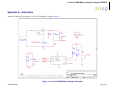
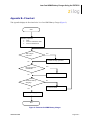
Application Note
Low-Cost NiMH Battery Charger
Using the Z8F0830
AN025902-0208
Abstract
–
This application note presents a concept for a simple,
low-cost nickel-metal hydride (NiMH) battery
charger using the Zilog’s 20-pin Z8 Encore!® F0830
series microcontroller.
–
The battery charger design uses the 5.5296 MHz
internal clock. An internal reference voltage of 2 V is
applied to the on-chip analog-to-digital converter
(ADC), which is used to monitor battery voltage, current, and temperature.
Note: The source code associated with this
application note is available under
Z8 Encore! Applications Code
Library in Application Sample
Libraries on www.zilog.com.
Features
The key features of the battery charger design
include:
Setting maximum charging time between 4
hrs and 4.5 hrs (charging at C/4 of 2000
mAh)
Over-voltage termination
•
Bad battery detection using battery voltage/
current measurement
•
LED indication for battery charging and charge
completion
Discussion
NiMH batteries are an excellent choice for powering
high-drain devices such as digital cameras. They last
longer than alkaline batteries, and are less expensive.
The challenge with recharging NiMH batteries is
‘overcharging’. Overcharging an NiMH battery significantly reduces its operating life. With traditional
overnight chargers, they are left un-plugged. These
low-cost chargers seldom have a ‘charge complete
indicator,’ so that they are too easy to neglect.
A slow charge is technically more efficient than a fast
charge. The workaround is, create a low-cost charger
design that charges batteries with a maximum 4 hrs to
4.5 hrs charging cycle.
•
Minimal hardware required
•
Constant current charging using the Z8
Encore! F0830 pulse-width modulation
(PWM)
•
Fast charge = 0.25 C (500 mA) for 2000 mAh
battery
•
Ability to charge three serially connected 1.2 V
AAA batteries at up to 500 mA
•
In-circuit programming simplifies firmware
upgrades and evaluation
The advantage of this proposed design is its simplicity—fewer components reduce the cost of the circuit,
and implementation is fast and easy.
•
Battery voltage and current monitoring using
Z8 Encore! F0830 10-bit ADC
Hardware Architecture
•
Three methods for ending the charge cycle are:
– Detecting negative dv/dt
The hardware circuit is designed using the 20-pin Z8
Encore!® F0830 microcontroller. The design speci-
The circuit is designed to stop the charging cycle
when it detects negative dv/dt. The circuit continuously monitors battery voltage and current.
Copyright ©2008 by Zilog®, Inc. All rights reserved.
www.zilog.com
Low-Cost NiMH Battery Charger Using the Z8F0830
fies generally available components, and is simple to
build and test.
Timer
•
Internal precision oscillator (5.5296 MHz)
used to set the system clock.
The Z8 Encore!® F0830 MCU provides two timers,
Timer0 and Timer1. Timer0 is initialized to generate
the PWM output at a frequency of 10 kHz. Timer1
generates regular 50 µ s interrupts, during which
Flags are set or reset depending on the task to be
completed. The initialization routines are available in
timer.c file.
•
Internal PWM frequency for charging set to 10
kHz.
Feedback
The following Z8 Encore! F0830 microcontroller
features are used in the design:
The design uses a 7.5 VDC regulated external power
supply to provide 3.3 VDD for the Z8 Encore! F0830
MCU.
The feedback module provides the logic for calculating average voltage and current from the values captured by the ADC. The routines are available in
feedback.c file.
For details on hardware connections, see Appendix
A—Schematics on page 4.
Charging
Software Implementation
The software design consists of the following modules:
•
ADC
•
Timer
•
Feedback
•
Charging
For information on each module, see Appendix B—
Flowchart on page 5.
ADC
The Z8 Encore!® F0830 MCU provides eight ADC
channels. Three channels are used to read the battery
voltage, current, and temperature using an internal
voltage reference of 2 V. A set of readings is obtained
from each of the channels and stored in an array
which is later used for calculating the average voltage and average current. The ADC values are read
with respect to timed intervals. The initialization routines are available in adc.c file.
AN025902-0208
After calculating the average battery voltage and battery current, the loop parameter is calculated using
the proportional and integral (PI) loop. The routine
returns an error percentage with respect to its previous value. The error percentage is used to stabilize
the current flowing into the battery. The Ki and Kp
variables of the PI loop can be changed if required.
The routine is available in charger.c file.
Once the charging current is stabilized, the battery is
in the charging state. The charging routine is
designed to prevent overcharging and overheating.
The charge cycle is ended when any one of the following occur:
•
Negative dv/dt is detected.
•
Maximum charge time as set in the charging
routine elapses.
•
Maximum battery voltage is detected.
•
A bad battery is detected.
The charging current is controlled by increasing or
decreasing the PWM duty cycle. This process is
adapted with respect to the error percentage returned
by the PI loop, thus stabilizing the charging current.
The routines for the above tasks are available in
charger.c file.
Page 2 of 7
Low-Cost NiMH Battery Charger Using the Z8F0830
Overcharging Protection
References
Three additional charge termination checks are considered in our design. Therefore, if negative dv/dt is
not detected for any reason, then the application terminates charging based on over-voltage or timeout to
prevent overcharging.
The documents associated with Z8 Encore! F0830
available on www.zilog.com are provided below:
•
Z8 Encore!® F0830 Series with Extended
Peripherals Product Brief (PB0161).
You can set over-voltage (MAX_BATT_VOLT), current set limit (CURRENT_MAMP), maximum count
of negative slope (MAX_SLOP_COUNT), and maximum charging time (BATTERY_TIMEOUT) to the
desired values in charger.h file and timer.h
file.
•
Z8 Encore!® F0830 Series Product Specification (PS0251).
•
Z8 Encore!® F083x Series Programming Specification (PRS0010).
Z8 Encore!® Based AA type NiMH and NiCD
Battery Charger Reference Design (AN0229).
Z8 Encore!®-Based SLA Battery Charger
Application Note (AN0223).
Z8 Encore!®-Based NiMH Battery Charger
Application Note (AN0222).
Z8 Encore!®-Based NiCD Battery Charger
Application Note (AN0221).
Z8 Encore! XP®-Based Lithium Ion Battery
Charger (AN0218).
Z8 Encore!®-Based Battery Charger (AN0137)
eZ8 CPU Core User Manual (UM0128).
Example: Maximum timeout calculation; if battery
rating is 400 mAh and charging current is 200 mA.
•
•
•
Maximum Time (Hour) = Rated battery current/
charging current = 400/200 = 2 hrs
•
Set the macro in timer.h file for 2 hrs:
•
# BATTERY_TIMEOUT 2 /* maximum
battery charging time */
•
•
Results
The batteries are charged in CONSTANT-CURRENT mode up to 500 mA. Charging is terminated
when negative dv/dt is detected, maximum battery
voltage is detected, or the maximum charge time
elapses.
Summary
This application note describes a low-cost NiMH battery charger implementation using the Z8 Encore!®
F0830 MCU. The MCU’s internal 10-bit ADC makes
accurate recharging possible, and the overall design
ensure that the NiMH batteries are never overcharged.
The design also makes use of PWM to provide an
accurate DC-DC converter (buck) implementation,
so that the hardware cost is low.
AN025902-0208
Page 3 of 7
Low-Cost NiMH Battery Charger Using the Z8F0830
Appendix A—Schematics
Appendix A displays the schematics of Low-Cost NiMH Battery Charger (Figure 1).
Figure 1. Low-Cost NiMH Battery Charger Schematic
AN025902-0208
Page 4 of 7
Low-Cost NiMH Battery Charger Using the Z8F0830
Appendix B—Flowchart
This Appendix displays the flowchart for the Low-Cost NiMH Battery Charger (Figure 2).
Start
Initialize peripheral:
• ADC,
• Timer in continuous mode
• Timer in PWM mode
ADC sample
collected?
Yes
Calculate PI loop parameter
No
PI loop parameter
calculated??
Yes
Check for termination
No
Terminate battery
charging?
No
Load new PWM
Yes
Stop charging
End
Figure 2. Flowchart for NiMH Battery Charger
AN025902-0208
Page 5 of 7
Low-Cost NiMH Battery Charger Using the Z8F0830
Appendix C—Battery Technology
The four mainstream battery chemistries (NiCd,
NiMH, SLA, Li-Ion) have different charging and discharging characteristics. Long-term battery life and
performance is critically dependent on how the battery is charged. It is therefore critical to charge the
respective batteries with the mechanism they require.
It is also important to know when to terminate charging. Battery overcharging causes in poor performance and can damage the battery in extreme cases.
Different battery types behave differently in full
charge condition and thus require specific charge termination techniques.
Charging a Nickel-Metal Hydride
(NiMH) Battery
NiMH batteries exhibit higher power density compared to their NiCd counterparts. The per-cell voltage
of the NiMH battery type is 1.2 V, similar to NiCd
batteries.
NiMH batteries must be charged via the constant current charging method. While charging, as the voltage
crosses the full charge point, the voltage drop is not
as low as it is in NiCd batteries. Consequently, negative dv/dt charge termination is usually not recommended for these batteries.
Instead of the drop in cell voltage, the battery tends to
plateau after a small drop. This flat region is the preferred indication for full battery charging, rather than
the drop. Consequently, this termination mechanism
is called zero dv/dt termination.
NiMH batteries do not suffer from memory effect as
do NiCd batteries. As a result, they replace NiCd battery types in applications such as cell phones because
the increase in price is justified by the reduction in
weight and absence of memory effect.
AN025902-0208
Page 6 of 7
Low-Cost NiMH Battery Charger Using the Z8F0830
Warning:
DO NOT USE IN LIFE SUPPORT
LIFE SUPPORT POLICY
ZILOG’S PRODUCTS ARE NOT AUTHORIZED FOR USE AS CRITICAL COMPONENTS IN LIFE
SUPPORT DEVICES OR SYSTEMS WITHOUT THE EXPRESS PRIOR WRITTEN APPROVAL OF
THE PRESIDENT AND GENERAL COUNSEL OF ZILOG CORPORATION.
As used herein
Life support devices or systems are devices which (a) are intended for surgical implant into the body, or (b)
support or sustain life and whose failure to perform when properly used in accordance with instructions for
use provided in the labeling can be reasonably expected to result in a significant injury to the user. A
critical component is any component in a life support device or system whose failure to perform can be
reasonably expected to cause the failure of the life support device or system or to affect its safety or
effectiveness.
Document Disclaimer
©2008 by Zilog, Inc. All rights reserved. Information in this publication concerning the devices,
applications, or technology described is intended to suggest possible uses and may be superseded. ZILOG,
INC. DOES NOT ASSUME LIABILITY FOR OR PROVIDE A REPRESENTATION OF ACCURACY
OF THE INFORMATION, DEVICES, OR TECHNOLOGY DESCRIBED IN THIS DOCUMENT.
Z I L O G A L S O D O E S N O T A S S U M E L I A B I L I T Y F O R I N T E L L E C T U A L P R O P E RT Y
INFRINGEMENT RELATED IN ANY MANNER TO USE OF INFORMATION, DEVICES, OR
TECHNOLOGY DESCRIBED HEREIN OR OTHERWISE. The information contained within this
document has been verified according to the general principles of electrical and mechanical engineering.
Z8, Z8 Encore!, and Z8 Encore! XP are registered trademarks of Zilog, Inc. All other product or service
names are the property of their respective owners.
AN025902-0208
7
Page 7 of 7
![[ AN 0614 ] I F](http://vs1.manualzilla.com/store/data/006435313_1-38aab84b606e33e62f5bc457d36ab56a-150x150.png)