1
Application Note
AES 128-Bit Implementation with
Z8 Encore! XP Microcontrollers
AN033801-0812
Abstract
This application note discusses how AES-128 encryption can be implemented with
Zilog’s Z8 Encore! family of 8-bit microcontrollers. The AES-128 standard is an encryption solution that has been developed to satisfy many rapidly-evolving security concerns
that have arisen within the computer and embedded chip industries. This standard employs
128-bit block data transfer and a 128-bit key to cipher and decipher plain data. The AES
algorithm was implemented in compliance with the NIST FIPS 197 that governs how data
is transferred via advanced encryption methods.
Implementing the AES-128 standard with Zilog’s Z8 Encore! XP MCUs offers high-speed
performance when undergoing a encryption/decryption process, resulting in a 1.8909 ms
cipher rate and a 2.604 ms decipher rate. The source code consumes a maximum of 2.5 KB
of MCU memory.
Zilog’s Z8 Encore! XP MCU also offers high level of protection from unauthorized
attempts to read or write to the embedded code within Flash program memory. Users can
select option bits for Flash Read Protect, Flash Write Protect, or both. The Flash Read Protect option bit disables external user read access to Flash Program Memory; the Flash
Write Protect bit disables external user access to program this Flash program memory.
These features allows all encryption and decryption code to be fully secured.
Note: There are two source code files associated with this application note. AN0338-SC01.zip
contains a full representation of the AES routines described herein. In AN0338-SC02.zip,
some lines of code in the main.c file have been commented out to facilitate testing cipher
and decipher times and memory usage when a terminal emulation program is not being
used. All source code has been tested with version 5.0.0 of ZDS II for Z8 Encore! XP
MCUs; both of these .zip files are available for download from the Zilog website. Subsequent releases of ZDS II may require you to modify the code supplied with this application
note.
Features
The application discussed in this document adheres to the following methodologies:
•
Observes the NIST FIPS 197 standard
•
Employs the AES algorithm suggested by NIST FIPS 197
•
Allows the user to cipher and test different character combinations
•
Fast, small-footprint implementation that can fit into a 4 KB Flash memory space
AN033801-0812
Page 1 of 34
AES 128-Bit Implementation with Zilog Microcontrollers
Application Note
Discussion
The Advanced Encryption Standard (AES) was released by the National Institute of Standards and Technology (NIST) in November 2001. It is the successor to the Data Encryption Standard (DES), which no longer satisfies today’s security requirements due to its
short key length of 56 bits. NIST had hosted a competition for different algorithm proposals that would replace DES; the best would become the new AES standard. In the final
round of the competition, the Rijndael algorithm, named after its Belgian inventors Joan
Daemen and Vincent Rijmen, won because of its security, ease of implementation and
small-footprint memory requirements.
There are currently three different versions of AES; all of them have a block length of 128
bits, whereas key length is allowed to be 128, 192 or 256 bits. For the purposes of this
application note, only a key length of 128 bits is discussed.
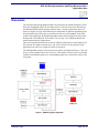
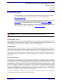
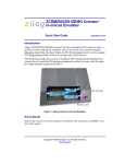
The AES algorithm consists of ten rounds of encryption, as indicated in Figure 1. The 128bit key is first expanded into eleven round keys, each of them 128 bits in size. Each round
includes a transformation that uses a corresponding cipher key to ensure the security of the
encryption.
Figure 1. AES Encryption Algorithm
AN033801-0812
Page 2 of 34
AES 128-Bit Implementation with Zilog Microcontrollers
Application Note
After an initial round of encryption, during which the first round key is XORed to the
plain text (the Addroundkey operation), nine equally-structured rounds follow. Each round
consists of the following operations:
•
Substitute Bytes
•
Shift Rows
•
Mix Columns
•
Add Round Key
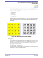
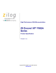
Both the key and the input data (also referred to as the state) are structured in a 4 x 4 matrix
of bytes. Figure 2 shows how the 128-bit key and the input data are distributed into the
byte matrices.
Figure 2. AES-128 Plain Data (Left) and Cipher Text (Right)
Encryption
The encryption process transforms plain data to encrypted data using a security key. While
encryption can be performed in different ways, most encryption use today is based on the
NIST FIPS 197 Standard, which involves the Add Round Key, Substitute bytes (Subbytes), Shift Rows and Mix Column.
The Add Round Key Operation
The Add Round Key operation is simple: the corresponding bytes of the input data and the
expanded key are XORed, as indicated in Figure 3.
AN033801-0812
Page 3 of 34
AES 128-Bit Implementation with Zilog Microcontrollers
Application Note
Figure 3. The XORed Add Round Key Operation
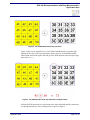
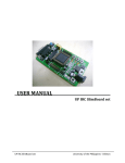
Figure 4 offers a more simplified view of the XORed Add Round Key operation, highlighting the first byte of the input data matrix and the first byte of the Add Round Key
matrix (both circled in the figure) that will go to the XOR operation (the circled plus sign)
that results in 0x71.
Figure 4. The XORed Add Round Key Operation, Simplified View
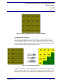
Perform the XOR operation for each element in the input and Add Round Key data matrices through the final byte. The resulting matrix is shown in Figure 5.
AN033801-0812
Page 4 of 34
AES 128-Bit Implementation with Zilog Microcontrollers
Application Note
Figure 5. The Resulting Matrix After the Add Round Key Operation
The Substitute Bytes Operation
The Subbytes operation is a nonlinear substitution method that can be implemented in different ways. One of these ways is to implement look-up tables consisting of a method
known as S_Box. The Subbytes algorithm substitutes the plain data with the corresponding
values found with the S_Box method.
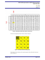
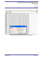
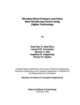
The S_Box shown in Figure 6 is displayed in X rows and Y columns. The first byte of the
matrix shown in Figure 5 is 0x71h, or 71. Converting this number to an XY format essentially means that the first digit, 7, represents the X (row) value and the second digit, 1, represents the Y (column) value. The intersection of these two values, 0x71h, will be
substituted by the S_Box value, 0xa3h, as highlighted in Figure 6 and indicated in the
first byte value shown in Figure 7.
AN033801-0812
Page 5 of 34
AES 128-Bit Implementation with Zilog Microcontrollers
Application Note
Figure 6. Substituting a Data Value with an S_Box Value
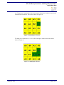
The result of computing all S_Box values is shown in Figure 7.
Figure 7. Substituted Element Using S_Box
Substituting all of the elements of the matrix using the S_Box will result in the values
shown in Figure 8.
AN033801-0812
Page 6 of 34
AES 128-Bit Implementation with Zilog Microcontrollers
Application Note
Figure 8. The Resulting Matrix After the Subbytes Operation
The Shift Rows Operation
The Shift Rows operation processes a data matrix in row-by-row fashion. The first row
remain unchanged, while the second row of the 4 x 4 byte input data (the user input) is
shifted one byte position to the left in the matrix. Subsequently, the third row is shifted
two byte positions to the left, and the fourth row is shifted three byte positions to the left.
Figure 9 illustrates how this Shift Rows operation works.
Figure 9. The Shift Rows Operation
In Figure 9, the first row remains unshifted, and the second row is shifted to the right by 1
cell. All elements in the second row are shifted 1 position to the left to, essentially, place
the first byte of the 2nd row, A3, into the 4th byte position (indicated in green in Figure
AN033801-0812
Page 7 of 34
AES 128-Bit Implementation with Zilog Microcontrollers
Application Note
10). This process is repeated twice for all elements in the third row and three times for all
elements in the fourth row. The result is shown in Figure 10.
Figure 10. Shifting the 2nd Row
The third row is shifted twice (i.e., two cells to the right), which results in the matrix
shown in Figure 11.
Figure 11. Shifting the 3rd Row
AN033801-0812
Page 8 of 34
AES 128-Bit Implementation with Zilog Microcontrollers
Application Note
The fourth and final row is shifted three times (i.e., three cells to the right), which results
in the matrix shown in Figure 12.
Figure 12. Shifting the 4th Row
This process of shifting all four rows is repeated with every round of encryption until all
ten rounds are completed.
The Mix Column Operation
Following the Shift Row operation is the Mix Column operation, which is the final process of the four encryption operations, and the most complex step in the AES-128 implementation.
The Mix Column operation processes a data matrix in column-by-column fashion. In principle, only a matrix multiplication operation must be performed. To make this operation
reversible, the usual addition and multiplication operations are not used. In an AES implementation, Galois field operations are used instead.
The Galois Field
A finite field1 is a field that exhibits a finite field order (i.e., a sequence of elements); this
finite field is also called a Galois field. The order of a finite field is always represented by
a prime number or the exponent of a prime number (as postulated by Birkhoff and Mac
Lane, 1996). Because a discussion about the Galois field is beyond the scope of this document, or to learn more about the Galois field, please refer to the Finite Field discussion in
Wolfram Mathworld.
In the Mix Column operation, a Galois field multiplication of matrix elements is implemented by shifting each value in a matrix to the left by one. If the value is greater than
0x80, the shifted value is returned and XORed from 0x1B. While the mathematical details
are beyond the scope of this document, it is important to know that in a Galois field, an
addition operation corresponds to an XOR, and a multiplication corresponds to a more
1. A field, as opposed to a matrix, is an algebraic structure in which the operations of addition, subtraction, multiplication and division (except by zero) can be performed.
AN033801-0812
Page 9 of 34
AES 128-Bit Implementation with Zilog Microcontrollers
Application Note
complex equivalent. The fact that there are many instances of 01 in the multiplication
matrix of the Mix Column operation makes this step easily computable.
The following procedure shows how to implement a Mix Column operation, in which it is
assumed we have two 4x4 matrices; namely, the data matrix and a scratch matrix.
1. From the data matrix, take the XORed result of the first row and save this result to the
variable X.
2. From the data matrix, take the XORed result of the first and second bytes of the first
row, multiply this result by 2, and save this new result to the variable Y.
3. From the data matrix, take the first byte and save it to a third variable, Z, then XOR
the three X, Y and Z variables and place the result into the first byte of the scratch
matrix.
4. From the data matrix, take the XORed result of the second and third bytes, multiply
this result by 2, and save the result to the Y variable.
5. Take the XORed result of the X, Y and Z variables and place this result into the second
byte of the scratch matrix.
6. From the data matrix, take the XORed result of the third and fourth bytes of the first
row, multiply this result by 2, and save the result to the Y variable.
7. Take the XORed result of the X, Y and Z variables and place the result into the third
byte of the scratch matrix.
8. From the data matrix, take the third byte of the first row and XOR this byte to the Z
variable, multiply the result by 2, and save the result to the Y variable.
9. Take the XORed result of the X, Y and Z variables and place the result into the fourth
byte of the scratch matrix.
10. Repeat Steps 1 through 9 for the second, third and fourth rows.
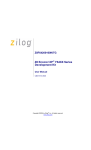
Figure 13 diagrams the results of this Mix Column implementation.
AN033801-0812
Page 10 of 34
AES 128-Bit Implementation with Zilog Microcontrollers
Application Note
Figure 13. Mix Column with Galois Multiplication
Key Expansion
Key expansion refers to the process in which the 128 bits of the original key are expanded
into eleven 128-bit round keys. Each next round key (n+1) must be calculated from each
round key (n).
Observe the following procedure to compute the new first column of the next round key:
1. All of the bytes of the old fourth column must be substituted using the Subbytes operation. These four bytes are shifted vertically by one byte position and then XORed to
the old first column. The result of these operations is the new first column.
2. Columns 2 to 4 of the new round key are calculated as shown:
[new second column] = [new first column] XOR [old second column]
[new third column] = [new second column] XOR [old third column]
[new fourth column] = [new third column] XOR [old fourth column]
AN033801-0812
Page 11 of 34
AES 128-Bit Implementation with Zilog Microcontrollers
Application Note
Decryption
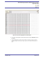
Decryption is the inverse of the encryption operation and follows the same process discussed in the The Substitute Bytes Operation section on page 5, except that it uses an
Inverse S-Box method instead of the S-Box method, as indicated in Figure 14.
Figure 14. Inverse S-Box: Substitution Values for the XY Byte (in Hexadecimal Format)
Hardware Implementation
This AES-128 application was implemented and tested using a small memory model.
Essentially, any Zilog microcontroller can be used for its implementation. We used a
Z8F082A MCU in this application to highlight the small memory footprint of its firmware. Using a Z8F082A Development Kit connected to a desktop PC via the HyperTerminal emulation program, the user can enter a 16-character string. HyperTerminal is used to
display the plain text, the ciphered text and the decrypted text.
Software Implementation
The AES-128 algorithm was implemented in C using ZDS II version 5.0.0 for Z8 Encore!.
Table 1 describes the commands used to perform the FIPS 197-based encryption and
decryption processes.
AN033801-0812
Page 12 of 34
AES 128-Bit Implementation with Zilog Microcontrollers
Application Note
Table 1. Encryption/Decryption Commands
Command
Description
void Generate_Key();
Used to generate the key required in 10 rounds of the Add
Round Key operation.
unsigned char G_Multiply(unsigned char
value);
This function is called in the decryption process, which
performs a Galois multiplication before performing the Mix
Column operation.
void mix_column(unsigned char
*Plain_Data);
This function is called by void add_S_Box_and_shift(unsigned
char *Plain_Data, unsigned char turn).
void add_S_Box_and_shift(unsigned char This function adds (XORs) the round key to the plain data.
*Plain_Data, unsigned char turn);
The output of the XORed plain data and the round key is
replaced by a Subbytes (S_Box) value. Every column is then
mixed by multiplication.
void inv_add_S_Box_and_shift(unsigned
char *Plain_Data, unsigned char turn);
This function adds (XORs) the round key to the encrypted
data. The output of the XORed encrypted data and the round
key is replaced by an inverse Subbytes (inv_S_Box) value.
Every column is then mixed by multiplication.
void cipher_AES(unsigned char
*Plain_Data);
Used to cipher 16-character data. If there are more than 16
characters, it must be subdivided into 16-byte parts.
void decipher_AES(unsigned char
*Plain_Data);
Used to decipher 16-character cipher data. If the data is more
than 16 characters, it must be subdivided into 16-byte parts.
Equipment Used
The tools used to develop this AES-128 application are:
•
The most recent version of the ZDS II IDE for Z8 Encore! devices
•
Z8F082A Development Kit
•
USB-to-9-pin serial cable
Testing Procedure
To build, configure and test the AES-128 algorithm on your own Z8F082A Development
Kit, observe the following procedure.
1. Download the most recent version of ZDS II – Z8 Encore and install it on your PC.
Note: Website registration is required to download the ZDS II software. If you have already registered as a site user on zilog.com, simply log in to download ZDS II.
2. Download the AN0338-SC01 source code from the Zilog website and unzip it to an
appropriate project folder on your PC.
AN033801-0812
Page 13 of 34
AES 128-Bit Implementation with Zilog Microcontrollers
Application Note
3. Launch ZDS II – Z8 Encore.
4. In the ZDS II menu bar, navigate via the File menu to Open Project to display the
Open dialog box. Browse to the project folder containing the copy of AN0338-SC01
that you downloaded in Step 2. Within the AN0338-SC01 folder, select the .zdsproj
file, and click Open.
5. From the Configuration: drop-down menu, select Debug. In the left panel of the
screen, click General to open the General window. In the Build panel (on the center
right of the window), ensure that the Generate Debug Information checkbox is
selected. Return to the Configuration: drop-down menu, select Release, and repeat
these same tasks so that the Generate Debug Information checkbox is selected.
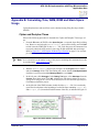
6. Additionally, with the .zdsproj project open, navigate via the Project menu in
ZDS II and select Settings. In the Code Generation pane, ensure that the Limit Optimization checkbox is not selected, and that Memory Model is set to Small, as shown
in Figure 15.
Figure 15. Code Generation Panel Settings
AN033801-0812
Page 14 of 34
AES 128-Bit Implementation with Zilog Microcontrollers
Application Note
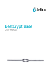
7. In the Debugger panel of the Settings window, in the Target pane, click the Setup
button to launch the Configure Target dialog box. In this dialog, ensure that the
Clock Source is set to External and that the Frequency is set to 20.00000 MHz. Click
OK to close the Configure Target dialog, then click OK a second time to close the
Project Settings dialog. If an IDE window appears, prompting you to rebuild the
affected files, click Yes to close this dialog and save your project settings.
8. On the left side of the ZDS II workspace area, click the + icon to expand the External
Dependencies menu, then double-click the SIO.h file. Ensure that _DEFBAUD is set
to 57600. If you must change this setting, ensure that you change it to 57600ul.
9. From the Build menu, choose Rebuild All to build the code and load it into the
Z8F082A MCU.
Observe the following instructions to configure HyperTerminal.2
1. To launch HyperTerminal, navigate via the PC’s Start menu to All Programs →
Accessories → Communications → HyperTerminal. Configure HyperTerminal to
reflect the settings shown in Figure 16.
Figure 16. HyperTerminal Properties
2. This AES-128 application was tested using HyperTerminal running on a Windows XP SP3 system.
AN033801-0812
Page 15 of 34
AES 128-Bit Implementation with Zilog Microcontrollers
Application Note
2. Click the Reset button in the ZDS II toolbar and wait a moment for the Enter 16
Characters: text string to appear in the HyperTerminal screen, as shown in Figure
17.
Figure 17. Initial AES-128 Screen in HyperTerminal
AN033801-0812
Page 16 of 34
AES 128-Bit Implementation with Zilog Microcontrollers
Application Note
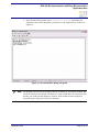
3. At this prompt, enter a 16-character string; for example, enter abcdefghijklmnop,
as indicated in Figure 18.
Figure 18. Entering a 16-Character String for Encryption
AN033801-0812
Page 17 of 34
AES 128-Bit Implementation with Zilog Microcontrollers
Application Note
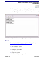
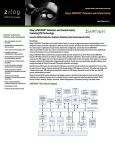
4. HyperTerminal will respond with Encryption in process, then display the
encrypted version of the string that you entered (i.e, the ciphered text), as shown in
Figure 19.
Figure 19. The 16-Character String, Encrypted
Note: The program will wait for you to enter a total of 16 characters, and will not respond until
at least 16 characters are entered. The Enter key is also considered to be a character; theoretically you could press the Enter key 16 times, which would cause the program to
encrypt/decrypt a string of 16 Enter key characters.
AN033801-0812
Page 18 of 34
AES 128-Bit Implementation with Zilog Microcontrollers
Application Note
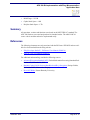
5. After encryption, the decryption process begins, and displays Decryption in process, followed by the decrypted text, as shown in Figure 20. This result, which shows
the decrypted version of the formerly-encrypted original string, confirms the veracity
of the AES-128 algorithm.
Figure 20. The 16-Character String: Encrypted, then Decrypted
Results
Upon testing, this AES 128-bit implementation yields the following specifications. See
Appendix B. Calculating Time, RAM, ROM and Stack Space Usage on page 22.
•
Clock Frequency = 20 MHz
•
Limit Optimization = Unchecked
•
Memory Model = Small
•
Configuration = Debug or Release
•
Cipher Time = 1.89 ms
•
Decipher Time = 2.60 ms
•
RAM Usage = 192 B (not including the stack)
AN033801-0812
Page 19 of 34
AES 128-Bit Implementation with Zilog Microcontrollers
Application Note
•
ROM Usage = 2355 B
•
Cipher Stack Space = 14 B
•
Decipher Stack Space = 17 B
Summary
All operations, routines and functions were based on the NIST FIPS 197 standard. The
AES-128 firmware was tested and produced its intended results. The AN0338-SC01
source code is modular and can be implemented easily.
References
The following documents are each associated with the Z8 Encore! XP MCU and are available free for download from the Zilog website.
•
Zilog Developer Studio II – Z8 Encore! User Manual (UM0130)
•
eZ8 CPU Core User Manual (UM0128)
For additional understanding, consider the following sources:
•
Advanced Encryption Standard (AES), Federal Information Processing Standards Publication 197; November 26, 2001.
•
Rinjdael Cipher/128-Bit Version (Data Block and Key) Encryption, Enrique Zabala,
Universidad ORT, Montevideo, Uruguay
•
How AES Works, Eastern Kentucky University
AN033801-0812
Page 20 of 34
AES 128-Bit Implementation with Zilog Microcontrollers
Application Note
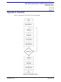
Appendix A. Flowchart
Figure 21 illustrates the flow of the AES 128-bit algorithm.
Figure 21. AES-128 Flow Chart
AN033801-0812
Page 21 of 34
AES 128-Bit Implementation with Zilog Microcontrollers
Application Note
Appendix B. Calculating Time, RAM, ROM and Stack Space
Usage
Cipher/decipher times and stack flow can be calculated using Zilog Developer Studio
(ZDS II).
Cipher and Decipher Times
Observe the following procedure to determine the Cipher and Decipher Time usage values.
1. From the File menu in ZDS II, select Open Project... to open the Open Project dialog
box. Browse to and select the AN0338.zdsproj project in this dialog, and click OK
to load it into the ZDS II IDE. In the main.c file, some lines must be commented out
to properly obtain the AES routine’s time usage, RAM and ROM, and stack usage.
Refer to Appendix C. AES Routine Without HyperTerminal on page 31 for an example of this commented-out code.
Note: As a convenience to the reader, a copy of the project containing this commented-out code
is provided in the AN0338-SC02.zip file.
2. With the AN0338.zdsproj project open, navigate via the Project menu in ZDS II
and select Settings. In the Code Generation pane, ensure that the Limit Optimization
checkbox is not selected and that Memory Model is set to Small.
3. In the left pane, click Debugger. In the Debug Tool pane, select Simulator from the
Current: drop-down menu. Click OK. A dialog box will appear, stating The project
settings have changed since the last build. Would you like to rebuild the affected files?
Click Yes to rebuild the project.
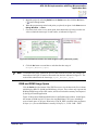
4. At the left side of the ZDS II window, double-click the main.c file if it is not already
open. Place break points at the beginning of each of the lines containing cipher_AES
and decipher_AES (located towards the bottom of the file), as indicated in Figure 22.
Figure 22. Break Points Location and Time
AN033801-0812
Page 22 of 34
AES 128-Bit Implementation with Zilog Microcontrollers
Application Note
5. Build the project by selecting Build from the Build menu, then click the Go button
(
) in the Debug toolbar.
6. When the program stops at the break points you placed, navigate via the View menu to
Debug Windows → Clock.
7. Check the clock value at every break point, then subtract the old value from the new
value to obtain the time usage of each routine, as indicated in Figure 23.
Figure 23. Break Point Location and Time Usage of cipher_AES (User_Input)
8. Click the Go button a second time to calculate the time usage of
Decipher_AES(User_Input).
Note: To calculate time usage, subtract the previous time from the new time. For example, the
time indicated in Figure 22 must be subtracted from the time indicated in Figure 23. The
result of this subtraction is the time usage, cipher_AES(User_Input).
RAM and ROM Usage Space
Click the Build tab at the bottom of the ZDS II screen to view the data in the Used column,
which displays RDATA (RAM) and ROM usage, in bytes. These values only represent the
ROM and RAM usage of the AES routine, and do not include the memory load imposed
by the HyperTerminal application.
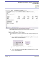
Figure 24 shows these ROM and RAM values in the Build output window. In this figure,
the amount of ROM used is 2355 bytes; the used RAM data is 212 bytes, including a
reserved stack space of 20 bytes. Because the STACK_SIZE is defined in the program as
20 bytes (14h), the used RAM data is actually 192 bytes; i.e., 212B – 20B = 192B.
AN033801-0812
Page 23 of 34
AES 128-Bit Implementation with Zilog Microcontrollers
Application Note
Figure 24. Build Output Window Showing Space Allocation Replacement
Cipher and Decipher Stack Space
Observe the following procedure to determine the Cipher and Decipher Stack Space values.
1. Click the Reset button in the ZDS II toolbar (highlighted in Figure 25), followed by
the Step Into button, to proceed through each individual step, one by one, to run the
function call to the Cipher/Decipher routine.
Figure 25. The RESET and Step Into Buttons in the ZDS II Toolbar
2. View the stack pointer values and stack RAM area, shown in Figure 26, by pressing
the ALT+3 keys simultaneously.
AN033801-0812
Page 24 of 34
AES 128-Bit Implementation with Zilog Microcontrollers
Application Note
Figure 26. Memory Window
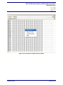
3. Initialize the stack RAM area starting from the current Stack Pointer + 1 (SP+1)
address location down to the top of unused RAM by right-clicking in the memory
window, then selecting Fill Memory from the pop-up menu, as shown in Figure 27.
The Fill Memory dialog box will appear, allowing you to enter your new address values, as shown in Figure 28. In this example, SP+1 = FFh and the top of unused RAM
is at address EBh, in which FFh – 14h = EBh. Figure 29 presents an example of such
newly-entered values in the area highlighted in red.
AN033801-0812
Page 25 of 34
AES 128-Bit Implementation with Zilog Microcontrollers
Application Note
Figure 27. Accessing the Fill Memory Pop-Up Menu
AN033801-0812
Page 26 of 34
AES 128-Bit Implementation with Zilog Microcontrollers
Application Note
Figure 28. Entering New Address Values in the Fill Memory Dialog
AN033801-0812
Page 27 of 34
AES 128-Bit Implementation with Zilog Microcontrollers
Application Note
Figure 29. 0xFF Values Highlighted in the Stack Space
4. Once again, step through the Cipher/Decipher function using the Step Into button in
the toolbar.
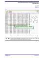
5. View the RAM stack area and count the number of used bytes. Figures 30 and 31
highlight examples of stack space usage, in green, for the cipher and decipher routines.
AN033801-0812
Page 28 of 34
AES 128-Bit Implementation with Zilog Microcontrollers
Application Note
Figure 30. Memory Window Showing Cipher Routine Stack Usage
AN033801-0812
Page 29 of 34
AES 128-Bit Implementation with Zilog Microcontrollers
Application Note
Figure 31. Memory Window Showing Decipher Routine Stack Usage
Note: To properly monitor the number of changed bytes, fill the stack space with 0xFF, starting
from the current SP+1 location down to the top of unused RAM.
AN033801-0812
Page 30 of 34
AES 128-Bit Implementation with Zilog Microcontrollers
Application Note
Appendix C. AES Routine Without HyperTerminal
The code presented below is an example of how to modify the main.c file by commenting out certain lines of code to properly obtain the AES routine’s time usage, RAM and
ROM, and stack usage.
/************************************************************************************************
** File: main.c
** Description: AES-128 User API.
**
** Copyright 2012 Zilog Inc. ALL RIGHTS RESERVED.
*
*************************************************************************************************
* The source code in this file was written by an authorized Zilog employee or a licensed
* consultant. The source code has been verified to the fullest extent possible.
*
* Permission to use this code is granted on a royalty-free basis. However, users are cautioned to authenticate the code
* contained herein.
*
* ZILOG DOES NOT GUARANTEE THE VERACITY OF THIS SOFTWARE; ANY SOFTWARE CONTAINED
* HEREIN IS PROVIDED "AS IS." NO WARRANTIES ARE GIVEN, WHETHER EXPRESS, IMPLIED, OR
* STATUTORY, INCLUDING IMPLIED WARRANTIES OF FITNESS FOR PARTICULAR PURPOSE OR
* MERCHANTABILITY. IN NO EVENT WILL ZILOG BE LIABLE FOR ANY SPECIAL, INCIDENTAL, OR
* CONSEQUENTIAL DAMAGES OR ANY LIABILITY IN TORT, NEGLIGENCE, OR OTHER LIABILITY
* INCURRED AS A RESULT OF THE USE OF THE SOFTWARE, EVEN IF ZILOG HAS BEEN ADVISED OF THE
* POSSIBILITY OF SUCH DAMAGES. ZILOG ALSO DOES NOT WARRANT THAT THE USE OF THE
* SOFTWARE, OR OF ANY INFORMATION CONTAINED THEREIN WILL NOT INFRINGE ANY PATENT,
* COPYRIGHT, OR TRADEMARK OF ANY THIRD PERSON OR ENTITY.
* THE SOFTWARE IS NOT FAULT-TOLERANT AND IS NOT DESIGNED, MANUFACTURED OR INTENDED
* FOR USE IN CONJUNCTION WITH ON-LINE CONTROL EQUIPMENT, IN HAZARDOUS ENVIRONMENTS,
* IN APPLICATIONS REQUIRING FAIL-SAFE PERFORMANCE, OR WHERE THE FAILURE OF THE
* SOFTWARE COULD LEAD DIRECTLY TO DEATH, PERSONAL INJURY OR SEVERE PHYSICAL OR
* ENVIRONMENTAL DAMAGE (ALL OF THE FOREGOING, "HIGH RISK ACTIVITIES"). ZILOG
* SPECIFICALLY DISCLAIMS ANY EXPRESS OR IMPLIED WARRANTY TO HIGH RISK ACTIVITIES.
*
************************************************************************************************/
#include <eZ8.h>
#include <sio.h>
#include <stdio.h>
#include "AES.h"
//volatile unsigned char User_Input[17] = {1,2,3,4,5,6,7,8,9,10,11,12,13,14,15,16};//comment this when getting the clock
usage
volatile unsigned char User_Input[16] = {1,2,3,4,5,6,7,8,9,10,11,12,13,14,15,16};//uncomment this when getting the clock
usage
#define STACK_SIZE 20
AN033801-0812
Page 31 of 34
AES 128-Bit Implementation with Zilog Microcontrollers
Application Note
//volatile unsigned char ReservedStackSpace[STACK_SIZE] _At 0x100;//comment this when getting the clock usage
volatile unsigned char ReservedStackSpace[STACK_SIZE] _At 0x100 - STACK_SIZE;//uncomment this when getting the
clock usage
/******************************************************************************
* Description: User Application
******************************************************************************/
void main( void )
{
/*******comment this when getting the clock usage*************/
// char i = 0;
// char data=0;
// int x=0;
// OSCCTL = 0xE7;
//unlocked sequence
// OSCCTL = 0x18;
// OSCCTL = 0x42;//crystal selected
// for(i=0;i<0xFFFF;i++);
//
//
//
//
DI();
init_uart(_UART0, _DEFFREQ, _DEFBAUD);
select_port(_UART0);
EI();
// User_Input[16] = '\0';
/****************************************/
while(1)
{
//
/*******comment this while loop when getting the clock usage********/
printf("Enter 16 Character: \n");
//
//
//
//
//
//
//
//
//
//
//
//
//
i=0;
data = 0;
while(1)
{
data = getchar();
putchar(data);
User_Input[i] = data;
i++;
if(i>=16)
{
break;
}
}
/*******************************************************/
//
printf("\r\nEncryption in process\r\n");//comment this when getting the clock usage
AN033801-0812
Page 32 of 34
AES 128-Bit Implementation with Zilog Microcontrollers
Application Note
cipher_AES(User_Input);
printf("%s", User_Input);//comment this when getting the clock usage
printf("\r\nDecryption in process\r\n");//comment this when getting the clock usage
decipher_AES(User_Input);
printf("%s\r\n", User_Input);//comment this when getting the clock usage
//
//
//
}
}
/******************************** END OF FILE ********************************/
AN033801-0812
Page 33 of 34
AES 128-Bit Implementation with Zilog Microcontrollers
Application Note
Customer Support
To share comments, get your technical questions answered, or report issues you may be
experiencing with our products, please visit Zilog’s Technical Support page at
http://support.zilog.com.
To learn more about this product, find additional documentation, or to discover other facets about Zilog product offerings, please visit the Zilog Knowledge Base at http://
zilog.com/kb or consider participating in the Zilog Forum at http://zilog.com/forum.
This publication is subject to replacement by a later edition. To determine whether a later
edition exists, please visit the Zilog website at http://www.zilog.com.
Warning: DO NOT USE THIS PRODUCT IN LIFE SUPPORT SYSTEMS.
LIFE SUPPORT POLICY
ZILOG’S PRODUCTS ARE NOT AUTHORIZED FOR USE AS CRITICAL COMPONENTS IN LIFE
SUPPORT DEVICES OR SYSTEMS WITHOUT THE EXPRESS PRIOR WRITTEN APPROVAL OF
THE PRESIDENT AND GENERAL COUNSEL OF ZILOG CORPORATION.
As used herein
Life support devices or systems are devices which (a) are intended for surgical implant into the body, or (b)
support or sustain life and whose failure to perform when properly used in accordance with instructions for
use provided in the labeling can be reasonably expected to result in a significant injury to the user. A
critical component is any component in a life support device or system whose failure to perform can be
reasonably expected to cause the failure of the life support device or system or to affect its safety or
effectiveness.
Document Disclaimer
©2012 Zilog, Inc. All rights reserved. Information in this publication concerning the devices, applications,
or technology described is intended to suggest possible uses and may be superseded. ZILOG, INC. DOES
NOT ASSUME LIABILITY FOR OR PROVIDE A REPRESENTATION OF ACCURACY OF THE
INFORMATION, DEVICES, OR TECHNOLOGY DESCRIBED IN THIS DOCUMENT. ZILOG ALSO
DOES NOT ASSUME LIABILITY FOR INTELLECTUAL PROPERTY INFRINGEMENT RELATED
IN ANY MANNER TO USE OF INFORMATION, DEVICES, OR TECHNOLOGY DESCRIBED
HEREIN OR OTHERWISE. The information contained within this document has been verified according
to the general principles of electrical and mechanical engineering.
Z8, Z8 Encore! and Z8 Encore! XP are trademarks or registered trademarks of Zilog, Inc. All other product
or service names are the property of their respective owners.
AN033801-0812
Page 34 of 34