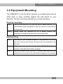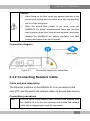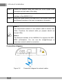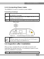
1
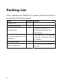
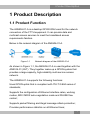
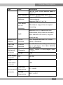
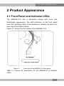
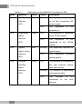
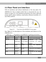
An Expert in Optical Communications User Manual AN5506-01-A GPON Optical Network Unit Version: A Code: MN000000943 Date: December 2011 FiberHome Telecommunication Technologies Co., Ltd. Version Version Description A Initial version are trademarks of FiberHome Telecommunication Technologies Co., Ltd. (Hereinafter referred to as FiberHome) All brand names and product names used in this document are used for identification purposes only and are trademarks or registered trademarks of their respective holders. All rights reserved No part of this document (including the electronic version) may be reproduced or transmitted in any form or by any means without prior written permission from FiberHome. Operation Safety Rules High optical power can cause bodily harm, especially to eyes. Never look directly into the end of the optical transmitter fiber jumper or the end of its active connector. Exercise care if you must bend fibers. If bends are necessary, the fiber bending radius should never be less than 38mm. Power socket overload, broken cables or broken plugs may cause electric shock or fire. Regular check-ups on power supply wires and cables are essential. If any appear damaged, replace at once. Use the power supply adapter provided in the package only. Using other adapters may cause equipment damage or operation failures. Install the equipment in a well ventilated environment without high temperatures or direct sunlight to protect the equipment and its components from overheating, which can result in damage. Avoid moisture, dampness and water damage. Equipment exposed to water cannot work normally and can be extremely hazardous due to shorting. Do not lay this equipment on an unsteady base. I Packing List When unpacking the AN5506-01-A, please check that all items in the packing list below are present. Name Number Remark AN5506-01-A 1 — Conformity certificate 1 — Contains an AN5506-01-A Document bag 1 GPON Optical Network Unit User Manual. DC power adapter with two conductors II The AN5506-01-A is equipped 1 with the 2-conductor DC pow er adapter. RJ45 crystal head 2 Mount-to-wall screw 2 — For securing the equipment on the wall. Contents 1 Product Description ..................................................... 1 1.1 Product Function ............................................................... 1 1.2 Product Type ..................................................................... 2 1.3 Technical Specification ...................................................... 2 2 Product Appearance .................................................... 5 2.1 Front Panel and Indicator LEDs ........................................ 5 2.2 Rear Panel and Interface .................................................. 7 3 Product Installation ...................................................... 8 3.1 Preparation........................................................................ 8 3.1.1 Unpacking Check .................................................... 8 3.1.2 Installation Precaution ............................................. 8 3.2 Equipment Mounting ......................................................... 9 3.3 Cable and Wire Connection ............................................ 10 3.3.1 Connecting Optical Fiber Jumper .......................... 10 3.3.2 Connecting Network Cable ................................... 11 3.3.3 Connecting Power Cable ...................................... 13 3.4 Inspection after Installation.............................................. 13 4 FAQs............................................................................ 15 1 Product Description 1 Product Description 1.1 Product Function The AN5506-01-A is a desktop GPON ONU used for the network connection of the FTTH equipment. It can provide data and multicast access services to meet the broadband access requirements families. Below is the network diagram of the AN5506-01-A. Figure 1-1 Network diagram of the AN5506-01-A As shown in Figure 1-1, the AN5506-01-A is used together with the AN5516-01 (OLT). They together make up a GPON system that provides a large-capacity, high-reliability multi-service access network. The AN5506-01-A supports the following functions: Uses GPON uplink that is compliant with ITU-T G.984 series of standards; Supports the configuration of Ethernet interface rates, working modes, MDI / MDIX auto-negotiation mode and PAUSE flow control; Supports packet filtering and illegal message attack protection; Provides performance statistics on all Ethernet lines; 1 1 Product Description Supports the DHCP Option82 to report the physical location information of the Ethernet interface; Supports the IGMP Snooping protocol; Supports L2 / L3 wire speed forwarding; Performs various QoS functions: supports global configuration of queue priority, flexible mapping of 802.1p value of packets and the strict-priority queue scheduling mode; Supports the AES-128 algorithm for data encryption of downlink data. 1.2 Product Type Table 1-1 lists the type and number of the interface supported by the AN5506-01-A. Table 1-1 Product Type AN5506-01-A Product type and its interface number Ethernet FE Ethernet GE Power Supply interface interface Jack — 1 2-conductor power socket. 1.3 Technical Specification Table 1-2 lists the technical specifications of the AN5506-01-A. Table 1-2 Technical specifications of the AN5506-01-A Type Item Description Service VLAN Supports the IEEE 802.1Q VLAN standard; Supports adding 802.1Q VLAN in tag or untag mode; parameter 2 1 Product Description Type Item Description The full 4096 VLAN address space is supported. MAC address The MAC address table size is 64. Multicast Supports IGMP Snooping and IGMP Proxy protocols; Supports IGMP v1 / v2 / v3. Wire speed L2 / L3 switching All interfaces support the wire speed forwarding. Supports 802.1p; supports the QoS QoS classification policy based on interface, MAC address and VLAN ID; Supports priority re-tag. Network side GPON interface interface Client side Ethernet interface interface Mechanical Dimension parameter Weight 300g DC 12V DC — <5W Power supply parameter One, compliant with the ITU-T G.984 series of standards. One RJ-45 interface. Supports full dup lex or half duplex, 10 / 100 / 1000 M bit/s self-adaption. 35mm×129mm×117mm (height×width ×depth) Power consumption parameter Operating Environmental temperature parameter Storage temperature -5℃ to 45℃ -20℃ to 70℃ 3 1 Product Description Type Item Environmental humidity 4 Description 10% to 90%, non-condensing 2 Product Appearance 2 Product Appearance 2.1 Front Panel and Indicator LEDs The AN5506-01-A has a streamline design with novel and fashionable appearance. The LED indicators on the front panel show the operating status of the equipment, thereby the users can learn about the status directly. Figure 2-1 shows the front panel of the AN5506-01-A. Figure 2-1 Front view of the AN5506-01-A front panel Table 2-1 shows the description for the AN5506-01-A indicator LEDs. 5 2 Product Appearance Table 2-1 Description for the AN5506-01-A indicator LEDs Name Meaning Color Status Description Power Power status Green ON The equipment is powered indicator on via the 2-conductor DC LED power supply. OFF The equipment is not powered on. PON Registration Green ON The equipment is registered to the GPON system. status indicator OFF LED The equipment registered to is the not GPON system. LOS Optical Red Blinking optical signal. signal status indicator OFF LED LAN Ethernet The equipment receives no The equipment optical signals. Green ON The interface is connected to interface the user terminal without status data transmission. indicator Blinking LED The interface is transmitting and receiving data. OFF The interface connected terminal. 6 receives to is not the user 2 Product Appearance 2.2 Rear Panel and Interface With all interfaces and buttons distributed on the rear panel, the AN5506-01-A has a simple model that is convenient for use. As shown in Figure 2-2, the interfaces and buttons from left to right are: power switch, power interface, reset button, Ethernet interface (×1) and PON interface. Figure 2-2 Front view of the AN5506-01-A rear panel See Table 2-2 for descriptions of the interfaces and buttons on the AN5506-01-A. Table 2-2 Description for the AN5506-01-A interfaces and buttons Interface/Button Meaning Type Description ON/OFF Switch Button Turns on or off the power. 12V DC Power 2-conductor Connects supply jack power supply 2-conductor jack adapter. Button Resets Reset Reset button LAN Ethernet Optical interace the DC power equipment manually RJ-45 interface PON the to Connects to the computer, router, etc. SC/PC Connects to the optical splitter 7 3 Product Installation 3 Product Installation 3.1 Preparation 3.1.1 Unpacking Check When unpacking the AN5506-01-A, please check that all items on the list are present and not damaged. If any item is missing or has been damaged, please contact local agencies of FiberHome immediately. 3.1.2 Installation Precaution Before installing the AN5506-01-A, please read the following thoroughly. The installation location must be free of excessive moisture and must be properly grounded for lightning protection. The selected installation position enables the connection between the AN5506-01-A and the outside. For example, there should be sufficient outlet space for power cables and network cables. The installation position guarantees adequate air flow to facilitate heat dissipation. The installation position provides good earth grounding conditions. 8 3 Product Installation 3.2 Equipment Mounting The AN5506-01-A can be either secured on a stable plane like an office desk or hung vertically against the wall based on your demand. The two mounting methods are introduced below: Desk top mounting Step 1 Take out the AN5506-01-A from the carton. Before delivery, four self-adhesive pads are pasted to the four corners on the bottom of the device. Step 2 Gently place the AN5506-01-A on a stable surface that guarantees ventilation on both the left and right sides. Wall mounting Step 1 According to the recesses distance of the AN5506-01-A, drive the two mount-to-wall screws delivered with the equipment into the wall. Step 2 Align the recesses on the bottom of the AN5506-01-A with the screws on the wall and fix them up gently. Step 3 Take your hands off the AN5506-01-A slowly and make sure the equipment is mounted on the wall with the support of the screws. 9 3 Product Installation 3.3 Cable and Wire Connection 3.3.1 Connecting Optical Fiber Jumper Cable and wire description The PON interface of the AN5506-01-A can be uplinked to the central office end OLT equipment via the optical fiber. Connection procedures Step 1 Plan the layout of the optical fiber jumper. Measure the distance from the PON interface of the AN5506-01-A to the ODF distribution frame and choose the optical fiber with an appropriate length for connection. Step 2 Loosen set screws on the fiber cover that is at the upper right corner on the bottom panel of the equipment, and remove the fiber cover. Step 3 Take off the anti-dust caps of the optical fiber jumper and the PON interface of the AN5506-01-A. Step 4 Connect one end of the optical fiber jumper to the ODF distribution frame. Step 5 Insert the other end of the optical fiber jumper to the PON interface at the bottom panel of the AN5506-01-A. Step 6 10 Fit on the fiber cover and fasten set screws. 3 Product Installation Caution: 1. When fitting on the fiber cover, pay special attention to the layout of the optical fiber and make sure they are smoothly led out of the wiring hole. 2. When the optical fiber jumper is not used, cover the AN5506-01-A’s optical interfaces and fibers with anti-dust caps to protect them from the dust and moisture, which may damage the AN5506-01-A’s optical interfaces and fiber jumpers and cause them fail to function. Connection diagram Figure 3-1 Connection diagram for optical fiber 3.3.2 Connecting Network Cable Cable and wire description The Ethernet interface of the AN5506-01-A is connected to the user’s PC and the switch via network cables to access data service. Connection procedures Step 1 Plan the layout of the network cable. Measure the distance from the AN5506-01-A to the user terminal and choose the network cable with an appropriate length for connection. 11 3 Product Installation Step 2 Secure the network cable and make the RJ-45 crystal head connectors at both ends of the cable. Step 3 Insert the crystal head at one end of the network cable into a LAN interface of the AN5506-01-A. Step 4 Insert the crystal head at the other end of the network cable into the Ethernet interface of the user’s computer or the switch. Note 1: The transmission distance of the network cable is shorter than 100m. Therefore, the network cable you prepare should not exceed 100m. Note 2: The Ethernet interface of the AN5506-01-A supports the MDI / MDIX self-adaption. You can use the straight-through or cross-over network cable for connection. Connection diagram Figure 3-2 12 Connection diagram for network cables 3 Product Installation 3.3.3 Connecting Power Cable The AN5506-01-A uses a 2-conductor power adapter. Connection procedures Step 1 Take out the DC power adapter with two conductors provided in the AN5506-01-A package. Step 2 Insert the plug at one end of the adapter into the 12V DC interface of the AN5506-01-A. Step 3 Insert the other end of the adapter into the mains supply socket. Figure 3-3 Connection diagram for power cables Note 1: This power adapter can convert 220V AC into 12V DC input to provide power supply for the AN5506-01-A. 3.4 Inspection after Installation After you have completed the wire and cable connection and subscribed the relevant services, it is necessary to power on and check the AN5506-01-A as below: Step 1 Turn on the power supply. 13 3 Product Installation Step 2 Observe the status of the power indicator LED. If the power indicator LED is illuminated, the equipment is normally powered on. Otherwise, check whether the power cable connection is correct. Step 3 Observe the status of the optical signal indicator LED. If the optical signal indicator LED is extinguished, the fiber connection is normal. Otherwise, check whether the optical fiber is correctly connected. Step 4 Observe the status of the network interface indicator LED. If the network interface indicator LED is illuminated or blinking, the network cable connection is normal. Otherwise, check whether the network cable is correctly connected. Step 5 During the equipment operation, ensure the ventilation to avoid abnormal events caused by overheating. When any abnormality occurs, contact the local office of FiberHome for replacement. 14 4 FAQs 4 FAQs Q: All indicator LEDs are extinguished after power-on. A: 1. Check whether the power cable is correctly connected; 2. Check whether the power switch on the equipment’s rear panel is in the ON position. Q: The equipment fails to work. A: 1. If the equipment works abnormally, check whether the power is connected normally or the voltage is not within specifications; 2. If the equipment is overheated, check the ventilation. Make sure the equipment is not exposed to direct sunshine or is near the heat source. Q: The optical signal indicator LED is illuminated. A: 1. Check the received optical power levels with an optical power meter. Excessively low receive optical power may indicate the fiber is faulty; 2. Check whether the optical fiber is connected normally to the appropriate interface; 3. The received optical power at the ONU exceeds the normal power range (the optical power is too low or overload); 4. The ONU optical module is aged or damaged. 5. Check if the equipment at the central office end is operating normally. Q: The network interface indicator LED is extinguished. A: 1. Check whether the network cable is damaged or incorrectly 2. Check whether the wiring color-coding scheme of the network connected; cable is incorrect. If yes, replace the original network cable with a standard CAT-5 twisted-pair network cable. 3. Check if the network cable length exceeds the allowed range. 15 FiberHome Telecommunication Technologies Co., Ltd. Tel: +86 27 8769 1549 Address: No. 5 Dongxin Rd., Hongshan Dist., Fax: +86 27 8769 1755 Wuhan, China Website: www.fiberhomegroup.com Zip code: 430073