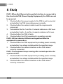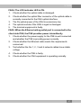
1
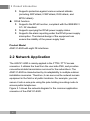
An Expert in Optical Communications User Manual AN5121-8GR PON Optical Network Unit Version: A Code: MN000001902 Date: September 2014 FiberHome Telecommunication Technologies Co., Ltd. Version Version Description A Initial version. are trademarks of FiberHome Telecommunication Technologies Co., Ltd. (Hereinafter referred to as FiberHome) All brand names and product names used in this document are used for identification purposes only and are trademarks or registered trademarks of their respective holders. All rights redserved No part of this document (including the electronic version) may be reproduced or transmitted in any form or by any means without prior written permission from FiberHome. Information in this document is subject to change without notice. Contents 1 Safety Precautions ............................................................. 1 2 Product Introduction.......................................................... 3 2.1 Product Overview ...........................................................3 2.2 Network Application........................................................6 2.3 Technical Specifications..................................................7 3 Product Appearance ........................................................ 10 3.1 Appearance..................................................................10 3.2 Indicator LED Description .............................................14 3.3 Interface Description.....................................................15 3.3.1 3.3.2 3.3.3 3.3.4 Interfaces of the Waterproof Shell .......................15 Interface of the Equipment..................................16 Introduction to the Pole Components ..................17 Introduction to the Cabinet Components .............18 4 Production Installation .................................................... 20 4.1 Installation Preparation .................................................20 4.2 Plane Mounting Mode ...................................................20 4.3 Pole-holding Mounting Mode.........................................21 4.3.1 4.3.2 4.3.3 4.3.4 Installation Flow Chart ........................................21 Pole Mounting Mode...........................................22 Securing the Equipment .....................................25 Connecting Wires and Cables.............................27 4.4 Wall Mounting Mode .....................................................34 4.4.1 Installation Flow Chart ........................................34 4.4.2 Wall Mounting Mode ...........................................35 4.4.3 Securing the Equipment .....................................38 4.4.4 Connecting Wires and Cables.............................39 4.5 Cabinet Mounting Mode................................................39 4.5.1 4.5.2 4.5.3 4.5.4 Installation Flow Chart ........................................39 Installing the Mounting Ears................................40 Cabinet Mounting Mode......................................41 Connecting Wires and Cables.............................43 4.6 Check after Installation .................................................44 5 FAQ ...................................................................................... 46 1 Safety Precautions 1 Safety Precautions Large-power laser is dangerous to human body, especially to eyes. Do not face the pigtail fiber of the optical transmitter or the end of the fiber cable connector to eyes. Power sockets with too heavy load or damaged cables and connectors may cause electric shock or fire. Regularly check related electric cables. If any electric cable is damaged on appearance, replace the electric cable immediately. When inserting the power connector of the device into an external power socket, make sure that the external power socket is close enough to the device, for easy operation. If the power cable of the device is straightly connected to an external power supply, switch off the external power supply before connecting the power cable. Hot-line operation is prohibited. Do not fix the product on an unstable support. Do not use the device when the grounding cable is damaged or no proper grounding cable is used. Perform regular electric inspection. If the grounding cable is damaged, replace it immediately. 1 1 Safety Precautions Install the silicon rubber waterproof band into the recess on the lower cover of the device case to ensure water proofing. 2 2 Product Introduction 2 Product Introduction The following introduces the functions, network applications and technical specifications of the AN5121-8GR. 2.1 Product Overview The AN5121-8GR is a GPON FTTB type optical network unit with the reverse PoE (Power over Ethernet) function specially developed for the network access at the outdoor environment, the building access of the broadcast, TV and telecommunication operators, etc. It can form a gigabit GPON system with the FiberHome GPON station central office devices. Its main features are described as follows: u Provides one GPON uplink port and eight FE downlink ports. Supports the DC 12V power supply or the power supply via the Ethernet using the PSE device compliant with the IEEE802.3 AF / AT standard. u It can be used together with the assorted protection case. This device features lightning protection, water proofing, power surge prevention, high and low temperature resistance, oxidation resistance, acid and basic corrosion resistance, and high reliability. It can be installed and operates under unfavorable outdoor conditions. u Performs the reverse feed function, and supports the power supply provided by the devices under it via the Ethernet physical line. Therefore, it does not require an external power supply at the installation site, which can lower the deployment and maintenance cost. 3 2 Product Introduction Function The AN5121-8GR supports the following functions: u Basic PON functions: 4 Uses the GPON connection in the uplink direction, meeting the ITU-T G.984 standard. 4 Supports multiple authentication modes, including the physical ID authentication, the password authentication, and the logical SN authentication. 4 Supports the downlink data encryption through the AES128 algorithm. u Basic Ethernet functions: 4 Supports the statistics about the Ethernet interface performance. 4 Supports the Ethernet interface working mode selection. The Ethernet interface can work under the 10 / 100 Mbit/s, full-duplex / half-duplex status in the auto negotiation or the forced mode. 4 Supports the LAN-port-based rate control function and the MAC address limit function. u VLAN related functions: 4 Supports the 802.1P and 802.1Q VLAN protocols. 4 Supports the VLAN stacking function. 4 Supports the VLAN transparent transmission and VLAN translation in the 1:1 / N:1 mode. 4 Supports VLAN tags carried by the multicast packets. 4 Supports the rate limiting function based on VLAN. u Multicast related functions: 4 Supports the multicast protocols such as the IGMP Snooping and the IGMP V2 / V3. 4 Supports the IPv6 multicast protocols such as the MLD Snooping and the MLD V1 / V2. 4 2 Product Introduction u QoS and ACL related functions: Supports the ACL function, which means traffic matching according to the ACL rules. 4 Has powerful QoS capabilities and supports three scheduling modes: SP, WRR and SP + WRR. 4 Supports queue mapping. The system can map to the corresponding priority queue according to the 802.1P priority and the DSCP priority. 4 Supports the flow rate control based on the flow classification rule and the re-marking of priority. 4 Supports bandwidth rate control based on the ONU, and guarantees the services with higher priorities. Access control functions: 4 Supports the DHCP line label function. 4 Supports the PPPoE+ function to identify users accurately. Equipment management and maintenance functions: 4 Supports the local WEB network management function. The operators can log in via the user LAN1 port to view the information of the AN5121-8GR and modify the logical SN and password of the ONU. 4 Supports managing the ONU remotely in the Telnet mode, and users can view the ONU status information and print the debug information. 4 Supports configuring the port modes, querying the port status, monitoring the overall power supply status of the equipment, and collecting and reporting the alarm information. Security related functions: 4 Supports limiting the quantity of MAC addresses at a certain port. 4 Supports the broadcast storm restriction function for the user port and the uplink port. 4 u u u 5 2 Product Introduction 4 Supports protection against various network attacks (including ARP attack, ICMP attack, DOS attack, and BPDU attack). RPoE function: 4 Supports the RPoE function, compliant with the IEEE802.3 AT / AF standard. 4 Supports querying the RPoE power supply status. 4 Supports the alarm reporting under the RPoE power supply interruption. The internal design of the equipment can ensure the stability of the power supply feed. u Product Model AN5121-8GR with eight FE interfaces 2.2 Network Application The AN5121-8GR is mainly applied in the FTTB / FTTV access scenarios. It obtains the feed from the user side PSE, and provides conventional data transmission services for the subscribers. The AN5121-8GR is characterized by its adaptability to multiple outdoor installation scenarios. Therefore, it can serve as the network access equipment in the field or at public locations. For example, you can secure it onto a wire pole using the pole-holding mounting mode to access public telephones. Figure 2.1 shows the network diagram for the common application scenarios of the AN5121-8GR. 6 2 Product Introduction Figure 2.1 The AN5121-8GR Application Network 2.3 Technical Specifications The technical specifications of the AN5121-8GR are listed in Table 2.1. Table 2.1 Type Service parameters The AN5121-8GR Technical Specifications Item Description VLAN Supports the IEEE 802.1Q / 802.1P VLANs and VLAN-based selective QinQ. One port supports translation of 16 unicast VLANs. Supports 4095 VLANs at most. 7 2 Product Introduction Table 2.1 Type Network side interface User side interface Mechanical parameters Power supply mode 8 The AN5121-8GR Technical Specifications (Continued) Item Description MAC address The capacity of the system MAC address table is 16K. Layer 2 line rate forwarding All ports support line rate forwarding. QoS Supports eight priority queues at most. Supports the SP, WRR, and SP + WRR scheduling modes. GPON interface One GPON interface is available, which meets the ITU-T G.984 standard. FE interface Eight FE interfaces are available, whose type is RJ-45. They support 10 / 100 Mbit/s full-duplex / half-duplex adaptation. Network cables are category-5 waterproof cables. The interfaces support the reverse PoE function based on the IEEE802.3 AF / AT standard. Waterproof shell size 80mm × 280mm × 340mm (height x width x depth). Equipment size 44mm × 230mm × 145mm (height x width x depth). Weight <1.5kg - Reverse PoE (Power over Ethernet) 2 Product Introduction Table 2.1 The AN5121-8GR Technical Specifications (Continued) Type Item Description Power consumption parameters - <10W Operating temperature -30℃ to 60℃ Storage temperature -55℃ to 125℃ Environmental humidity 0% to 80% (no condensation) Environment parameters 9 3 Product Appearance 3 Product Appearance 3.1 Appearance The following introduces the appearance of the AN5121-8GR and the waterproof shell for it. AN5121-8GR Figure 3.1 shows the appearance of the AN5121-8GR. Figure 3.1 The Appearance of the AN5121-8GR The equipment have ventilation holes on its top and both sides. All the interfaces and power switches are located on the front panel. The AN5121-8GR panel is shown in Figure 3.2. 10 3 Product Appearance Figure 3.2 The AN5121-8GR Panel Waterproof Shell The waterproof shell can be used together with the AN5121-8GR. Its top internal side is equipped with the waterproof bumper case, which can prevent the rain from entering the shell via the gaps. The appearance of the waterproof shell is shown in Figure 3.3. (1) Lock (2) LOGO (can be customized) Figure 3.3 Appearance of the Waterproof Shell The internal structure of the waterproof shell is shown in Figure 3.4. 11 3 Product Appearance (1) Cable binding ring (optional) (2) Optical fiber adapter (optional) (3) Optical splitter (optional) (4) Fiber splice tray (optional) (5) Earth ground component (optional) (6) Cable fixing component (optional) Figure 3.4 Internal Structure of the Waterproof Shell Tip: The pictures in this manual are for reference only. 12 3 Product Appearance The main components inside the waterproof shell are described in Table 3.1. Table 3.1 The Main Components inside the Waterproof Shell Component Description Quantity Cable binding ring (optional) Used to bind multiple network cables connecting the AN5121-8GR with the exterior. 4 Optical fiber adapter (optional) It is the flange. The fibers of the optical cable, after being branched, can be led into this component first and then led out to the exterior via it, for the convenience of maintenance. 10 Optical splitter (optional) Optional, used to split the signal from the previous optical cable. Users can select this component according to their demand. The splitters are available with two kinds of split ratio: 1:4 and 1:8. 1 Fiber splice tray (optional) Optional, used to splice and branch optical fibers. Users can select this component according to their demand. 1 Earth ground component (optional) Used to provide the earth ground point for the earth ground cable and the optical cable reinforced core inside the shell. 1 Cable fixing component (optional) Used to secure the network cable. 1 13 3 Product Appearance 3.2 Indicator LED Description The AN5121-8GR has various indicator LEDs on it. Except for the four round indicator LEDs (ACT, PD, PON, and LOS), the link status and duplex status indicator LEDs are located beside each LAN port. The description on each indicator LED is shown in Table 3.2. Table 3.2 Silkscreen Name Meaning ACT Working status indicator LED PD LOS PON 14 Description on Indicator LEDs of the AN5121-8GR Port receiving power supply feed indicator LED Optical signal status indicator LED PON status indicator LED Color Status Indicator LED Description Blinking The logical link has been set up. OFF The logical link has not been set up. ON The AN5121-8GR is receiving the power supply feed. OFF The AN5121-8GR is not receiving the power supply feed. ON The Rx optical power of the PON port is too low. OFF The Rx optical power of the PON port is normal. ON The AN5121-8GR is registered. OFF The AN5121-8GR is not registered. Green Green Red Green 3 Product Appearance Table 3.2 Silkscreen Name Description on Indicator LEDs of the AN5121-8GR (Continued) Meaning Link status indicator LED (left) Color Orange Status Indicator LED Description ON A certain equipment set is connected to the LAN port, without data transmission. Blinking A certain equipment set is connected to the LAN port, with data transmission. OFF No equipment set is connected to the LAN port. ON The port operates in the fullduplex mode. OFF The port operates in the half-duplex mode. LAN Duplex status indicator LED (right) Green 3.3 Interface Description 3.3.1 Interfaces of the Waterproof Shell The interfaces on the waterproof shell are shown in Figure 3.5. Figure 3.5 Interfaces on the Waterproof Shell 15 3 Product Appearance Table 3.3 Interfaces on the Waterproof Shell Serial Number Interface Description (1) Inlet for the optical fiber The optical cable is led into the waterproof shell through this interface. (2) Wiring interface for the network cable The network cable is led into the waterproof shell through this interface. (3) Outlet for the optical fiber The optical cable is led out of the waterproof shell through this interface. 3.3.2 Interface of the Equipment The AN5121-8GR interfaces are all on the front panel, as shown in Figure 3.6. Figure 3.6 The Equipment Interface (1) Protection earth ground interface (2) DC power interface (3) Power switch (4) Ethernet interface / RPOE interface (5) Console interface (6) GPON interface The description of each interface is shown in Table 3.4. 16 3 Product Appearance Table 3.4 Interfaces of the Equipment and Description Interface of the Equipment Description Protection earth ground interface Is used to connect the protection earth ground cable. DC power interface Is used to induct the external 12 V DC power supply. Power switch The power switch of the AN5121-8GR. Ethernet interface / RPOE interface Eight FE interfaces, used to access the LAN side users and receive the power supply feed of the PSE. Console interface Debugging serial port, used to debug the AN5121-8GR in the local connection mode. GPON interface Uplink PON interface, complying with the ITU-T G.984 standard. 3.3.3 Introduction to the Pole Components The pole components comprise the equipment base and clamp. The clamp is used to secure the equipment base on the wire pole. Figure 3.7 shows the equipment base. 17 3 Product Appearance Figure 3.7 The Base Figure 3.8 shows the clamp. Figure 3.8 The Clamp 3.3.4 Introduction to the Cabinet Components The cabinet components include the two mounting ears used to secure the equipment in the cabinet, as shown in Figure 3.9 and Figure 3.10. 18 3 Product Appearance Figure 3.9 Figure 3.10 The Mounting Ear on the Left Side of the Cabinet The Mounting Ear on the Right Side of the Cabinet 19 4 Production Installation 4 Production Installation The following introduces the preparations for equipment installation, fixing methods, cable connections, and check after device installation. 4.1 Installation Preparation Before installing the AN5121-8GR, check whether the following conditions are met: u The selected position is suitable for installing and using the AN5121-8GR. For example, check whether the power cables and network cables can be accessed. u The installation position provides good conditions for grounding of the workbench, wall, poles, and cabinet. u The workbench, wall, poles, and cabinet are firmly installed and can bear the weight of the equipment and its accessories. 4.2 Plane Mounting Mode The operation procedures are described as follows: 1. Take out the AN5121-8GR from the packaging box. 2. Lay the equipment gently on a stable plane, making sure that the protection earth ground cable interface on the front panel of the equipment is well grounded, as shown in Figure 4.1. 20 4 Production Installation Figure 4.1 Plane Mounting Mode 4.3 Pole-holding Mounting Mode 4.3.1 Installation Flow Chart The installation flow for the pole-holding mounting mode is shown in Figure 4.2. 21 4 Production Installation Figure 4.2 The Installation Flow for the Pole-holding Mounting Mode 4.3.2 Pole Mounting Mode The following introduces how to secure the waterproof shell on the wire pole. 22 4 Production Installation Tool Six point sockets Procedure 1. 2. Take out the equipment base and the clamp. Figure 4.3 shows the base and Figure 4.4 shows the clamp. Figure 4.3 The Base Figure 4.4 The Clamp Secure the equipment base onto the wire pole with the clamp, as shown in Figure 4.5, and fasten the clamp with the six point sockets. 23 4 Production Installation Figure 4.5 3. Securing the Equipment Base Hang the waterproof shell on the equipment base, as shown in Figure 4.6. 1) Find the hooks on the back of the waterproof shell, as indicated by (1) of Figure 4.6, and the gourd shaped holes on the equipment base, as indicated by (2) of Figure 4.6. 2) Align the hooks on the waterproof shell with the gourd shaped holes on the equipment base to hang the equipment from the top down. 24 4 Production Installation (1) Hook (2) Gourd shaped hole Figure 4.6 Hanging the Waterproof Shell 4.3.3 Securing the Equipment Tool A cross screwdriver Procedure 1. 2. Find the mounting holes at the bottom of the AN5121-8GR and the hooks inside the waterproof shell. Install the sheet metal delivered together with the equipment to the bottom of the equipment, as illustrated in Figure 4.7. 25 4 Production Installation Figure 4.7 3. Installing the Sheet Metal Align the mounting holes (as shown in ⑴ of Figure 4.8) at the bottom of the AN5121-8GR with the hooks (as shown in ⑵ of Figure 4.8) inside the waterproof shell, and hang the equipment on the waterproof shell as illustrated in Figure 4.8. 26 4 Production Installation (1) Mounting hole Figure 4.8 (2) Hook Securing the Equipment to the Waterproof Shell 4.3.4 Connecting Wires and Cables The following introduces how to connect the wires and cables for the equipment. 27 4 Production Installation The wires and cables to be connected for the equipment include u The optical cable u The earth ground cable u The network cable Tip: 1. Before leading the external wires and cables into the waterproof shell, you need to loosen the waterproof connector. 2. After completing the layout of the wires and cables, fasten the waterproof connector and seal the interface. 4.3.4.1 Connecting the Optical Cable The optical cable is used to connect the equipment optical interface and the external communication equipment. Tool u u A cross screwdriver Fiber connector preparing tool Procedure 1. Loosen the waterproof connector on the wiring hole at the right side of the waterproof shell. Lead one end of the optical cable into the waterproof shell via the wiring hole on the right side of the waterproof shell, as shown in ① of Figure 4.9. 2. 28 4 Production Installation Figure 4.9 3. 4. 5. 6. 7. 8. Connecting the Optical Cable Connect the reinforced core of the optical cable to the earth ground component, as shown in ② of Figure 4.9. Add a connector to the optical fiber in the optical cable, and connect the optical fiber to the flange, as shown in ③ of Figure 4.9. Connect the optical fiber led into the flange with the optical fiber in the optical splitter. Coil the optical fiber in the splitter onto the fiber spool when necessary. Connect a branch of the optical fiber in the optical adapter to the optical interface of the AN5121-8GR, as shown in ④ of Figure 4.9. Insert the optical fiber, which has been coiled onto the fiber spool as necessary, into the flange in the fiber adapter to 29 4 Production Installation connect with the external optical fiber, as shown in ⑤ of Figure 4.9. 9. Lead the external optical fiber out through the first wiring hole on the left side of the waterproof shell, as shown in ⑥ of Figure 4.9. 10. Connect the optical fibers led out from the waterproof shell to the optical interfaces of other AN5121-8GR equipment. 4.3.4.2 Connecting the Earth Ground Cable Tip: The equipment earth ground cable is used to connect the equipment and the external earth ground bar. u The equipment earth ground cables comprise the external earth ground cable and the internal earth ground cable. u Tool A cross screwdriver Procedure 1. Loosen the waterproof connector on the wiring hole at the right side of the waterproof shell. Lead one end of the external earth ground cable into the equipment via the wiring hole on the right side of the waterproof shell, as shown in ① of Figure 4.10. 2. 30 4 Production Installation (1) Waterproof connector Figure 4.10 3. 4. 5. (2) Connector post (3) Earth ground point Connecting the Earth Ground Cable Secure the external earth ground cable entering the equipment onto the connector post of the earth ground component, as shown in ② of Figure 4.10. Connect the other end of the external earth ground cable to the external earth ground bar. Secure one end of the internal earth ground cable to the earth ground point of the earth ground component, as shown in ③ of Figure 4.10. 31 4 Production Installation 6. Connect the other end of the internal earth ground cable to the earth ground hole of the AN5121-8GR, and coil the redundant part of the cable onto the fiber spool component, as shown in ④ of Figure 4.10. 4.3.4.3 Connecting the Network Cable The network cable is used to connect the external communication equipment and the AN5121-8GR. Tool A cross screwdriver Procedure 1. Loosen the waterproof connectors on the two wiring holes in the middle of the waterproof shell. Lead the RJ-45 connector on one end of the network cable into the equipment via the wiring hole on the right side of the waterproof shell, as shown in ① of Figure 4.11. 2. 32 4 Production Installation (1) Waterproof connector Figure 4.11 3. (2) Cable fixing component Connecting the Network Cable Loosen the cable fixing component, and lead the network cable through the cable fixing component, as shown in ② of Figure 4.11. 33 4 Production Installation 4. Insert the RJ-45 connector of the network cable into the AN5121-8GR's network interface. 4.4 Wall Mounting Mode 4.4.1 Installation Flow Chart The installation flow for the wall mounting mode is shown in Figure 4.12. 34 4 Production Installation Figure 4.12 The Installation Flow Chart for the Wall Mounting Mode 4.4.2 Wall Mounting Mode The following introduces how to mount the waterproof shell on the wall. 35 4 Production Installation Tool u u u An electric drill A hammer A cross screwdriver Procedure 1. 2. Take out the waterproof shell. Drill four holes on the wall with the electric drill. See Figure 4.13 for the positions and sizes of the holes. 36 4 Production Installation Figure 4.13 3. 4. Positions and Sizes of the Holes Install the expansion sleeve in the holes prepared. Install the four screws on the bottom of the waterproof shell into the expansion sleeve, and fasten the screws to secure the shell, as illustrated in Figure 4.14. 37 4 Production Installation (1) Screw (2) Expansion sleeve Figure 4.14 Securing the Waterproof Shell 4.4.3 Securing the Equipment Secure the AN5121-8GR in the waterproof shell. Refer to Securing the Equipment for the operation procedures. 38 4 Production Installation 4.4.4 Connecting Wires and Cables The following introduces how to connect the wires and cables for the equipment. Refer to 4.3 Pole-holding Mounting Mode→4.3.4 Connecting Wires and Cables for the operation procedures. 4.5 Cabinet Mounting Mode 4.5.1 Installation Flow Chart The installation flow chart for the cabinet mounting mode is shown in Figure 4.15. 39 4 Production Installation Figure 4.15 The Installation Flow Chart for the Cabinet Mounting Mode 4.5.2 Installing the Mounting Ears The following introduces how to install the mounting ears on the equipment. Tool A cross screwdriver 40 4 Production Installation Procedure 1. 2. Take out the mounting ears and screws delivered together with the equipment as accessories. Install the mounting ears on the left and right sides of the equipment respectively, as illustrated in Figure 4.16. Figure 4.16 Installing the Mounting Ears 4.5.3 Cabinet Mounting Mode Prerequisite When the mounting ears are used, users can install the AN51218GR inside a 19-inch cabinet. Tool A cross screwdriver 41 4 Production Installation Procedure 1. Take out the floating nuts and screws delivered together with the equipment, and fix the floating nuts horizontally at proper positions on the cabinet. Align the screw holes on the mounting ears and bent angle brackets on both sides of the AN5121-8GR. Push the mounting ears and bent angle brackets slowly toward the floating nuts until they touch closely. Then insert the screws into the screw holes on the floating nuts and tighten them, as shown in Figure 4.17. Take your hands away from the equipment slowly, so that the AN5121-8GR is mounted in the cabinet with the supporting of the screws. 2. 3. 42 4 Production Installation Figure 4.17 Installing the Equipment in the Cabinet 4.5.4 Connecting Wires and Cables The following introduces how to connect the wires and cables for the equipment. The wires and cables to be connected for the equipment include u The earth ground cable u The optical fiber u The network cable 43 4 Production Installation Procedure 1. Connect the earth ground cable for the equipment: connect one end of the earth ground cable to the earth ground point of the equipment, and the other end to the vertical mounting flange of the cabinet. Connect the optical fiber for the equipment: lead the optical fiber from the external into the cabinet, and inset the optical fiber plug into the optical fiber interface. Connect the network cable for the equipment: lead the network cable from the external into the cabinet, and insert the network plug into the network interface. 2. 3. 4.6 Check after Installation After all cables are connected and related services are requested from the carrier, power on and check the AN5121-8GR as follows: 1. Observe the PD indicator LED. If the PD indicator LED is ON, the equipment is normally powered on; otherwise, check whether the network cable connection is correct. 2. Observe the LOS indicator LED. If the LOS indicator LED is OFF, the optical cable is normally connected; otherwise, check whether the optical cable is correctly connected. 3. Observe the PON indicator LED. If the PON indicator LED is ON, the equipment is registered successfully; otherwise, check the ONU authority on the OLT side. 4. Observe the link status indicator LED (left). If the link status indicator LED (left) is ON or blinks, the network cables are normally connected; otherwise, check whether the network cables are correctly connected. 44 4 Production Installation 5. During the equipment running, ensure that it is correctly grounded to avoid failure. If any failure occurs, contact the local offices of FiberHome. 45 5 FAQ 5 FAQ FAQ1: When the Ethernet wiring outlet interface is connected to the client side PSE (Power Supply Equipment), the ONU can not be powered. 1. Check whether the power supply for the PSE is well connected and whether the PSE is providing power normally. 2. Check whether the network cable meets the requirements concerned. 3. Test whether the No.1 and No. 2 network cables are -48V ones and whether the No. 3 and No. 6 network cables are 0V ones. 4. Check whether the PSE is faulty. 5. Check whether the ONU equipment is operating normally. FAQ2: All the indicator LEDs are extinguished after the equipment is powered on. 1. Check whether the PSE equipment is providing power normally, and whether the voltage is stable within the specified range. 2. Check whether the network interface on the ONU side is correctly connected. FAQ3: The equipment stops running after normal operation for a period of time. 1. Check whether the PSE equipment is providing power normally, and whether the voltage is stable within the specified range. 2. Check whether the network interface on the ONU side is correctly connected. 46 5 FAQ FAQ4: The LOS indicator LED is ON. 1. Check whether the optical cable is damaged. 2. Check whether the optical fiber connector of the optical cable is normally connected to the ONU optical interface. 3. The Rx optical power of the ONU is excessively low. 4. The optical module of the ONU is aged or damaged. 5. The terminal equipment is faulty. FAQ5: When the Ethernet wiring outlet port is connected to the client side PSE, the PSE provides power intermittently 1. Check whether the power supply for the PSE is well connected and whether the PSE is providing power normally. 2. Check whether the Ethernet cable meets the requirements concerned. 3. Test whether the No.1, 2 , 3 and 6 network cables have stable voltage. 4. Check whether the PSE is faulty. 5. Check whether the ONU equipment is operating normally. 47 FiberHome Product Warranty We appreciate your purchase of FiberHome product. FiberHome warrants that the equipment will be free of defects in materials and workmanship for a period of 12 months from the date of purchase. The original, dated, bill of sale should be retained as proof of purchase and must be presented to FiberHome when the equipment is to be serviced under the provisions of this warranty. Customer Name Address / Zip Code Phone Model Number Serial Number Date of Purchase Invoice Number Dealer Name Dealer Address/Phone Please keep this card properly. No reissuance if lost. Dealer: (Seal) Warranty Description When you purchase a product offered by FiberHome from an authorized dealer, you have a 12-month warranty as standard, except for man-made causes. The warranty period begins on the date of invoice. For your lawful rights and interests, please notice: 1. 2. 3. The Warranty Card shall come into force with the seal of dealer. Please keep this card properly. No reissuance will be provided if you lose it and it becomes invalid if altered. In the event of a non man-made malfunction during the warranty period, FiberHome will repair or replace this product to its original operating condition free of charge. Warranty does not cover the following circumstances: 1. Damage or malfunction caused by transporting, loading and unloading. 2. Damage or malfunction caused by man-made reasons such as opening or remodel the machine on users’ own. 3. Damage or malfunction caused by unsatisfactory environment. 4. Damage or malfunction caused by force majeure incidents (such as fire, earthquake, lightning strike, war). 5. Damage or malfunction caused by failure to operate and maintain in accordance with the user’s manual 6. Damage of external parts such as equipment enclosure, power connector in operation 7. The inconsistence of the Warranty Card and the product serial number, or the warranty card has been altered. We provide paid repair and maintenance service for the products that are beyond the warranty scope. The final explanation rights of this warranty description are reserved by FiberHome. FiberHome Telecommunication Technologies Co., Ltd. No. 67 Guanggu Chuangye Street, Wuhan, Hubei, China Made in China Product Documentation Customer Satisfaction Survey Thank you for reading and using the product documentation provided by FiberHome. Please take a moment to complete this survey. Your answers will help us to improve the documentation and better suit your needs. Your responses will be confidential and given serious consideration. The personal information requested is used for no other purposes than to respond to your feedback. Name Contact Phone Number E-Mail To help us better understand your needs, please focus your answers on a single documentation or a complete documentation set. Documentation Name Code and Version Usage of the product documentation: 1. How often do you use the documentation? □Frequently □Rarely □Never □Other (please specify) 2. When do you use the documentation? □in starting up a project □in installing the product □in daily maintenance □in troubleshooting □Other (please specify) 3. What is the percentage of the operations on the product for which you can get instruction from the documentation? □100% □80% □50% □0% □Other (please specify) 4. Are you satisfied with the promptness with which we update the documentation? □Satisfied □Unsatisfied (your advice) 5. Which documentation form do you prefer? □Print edition □Electronic edition □Other (please specify) Quality of the product documentation: 1. Is the information organized and presented clearly? □Very □Somewhat □Not at all (your advice) 2. How do you like the language style of the documentation? □Good □Normal □Poor (please specify) 3. 4. 5. 6. Are any contents in the documentation inconsistent with the product? Is the information complete in the documentation? □Yes □No (please specify) Are the product working principles and the relevant technologies covered in the documentation sufficient for you to get known and use the product? □Yes □No (please specify) Can you successfully implement a task following the operation steps given in the documentation? □Yes (please give an example) □No (please specify the reason) 7. Which parts of the documentation are you satisfied with? 8. Which parts of the documentation are you unsatisfied with? Why? 9. What is your opinion on the Figures in the documentation? □Beautiful□Unbeautiful (your advice) □Practical□Unpractical (your advice) 10. What is your opinion on the layout of the documentation? □Beautiful□Unbeautiful (your advice) 11. Thinking of the documentations you have ever read offered by other companies, how would you compare our documentation to them? Product documentations from other companies: Satisfied (please specify) Unsatisfied (please specify) 12. Additional comments about our documentation or suggestions on how we can improve: Thank you for your assistance. Please fax or send the completed survey to us at the contact information included in the documentation. If you have any questions or concerns about this survey please email at [email protected]. FiberHome Telecommunication Technologies Co., Ltd. Address: No. 67 Guanggu Chuangye Street, Wuhan, Hubei, China Zip code: 430073 Website: www.fiberhomegroup.com