1
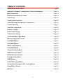
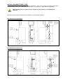
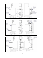
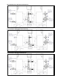
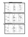
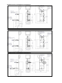
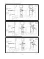
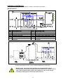
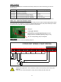
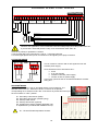
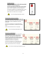
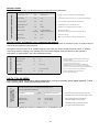
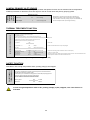
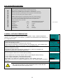
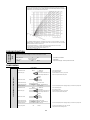
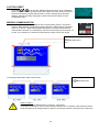
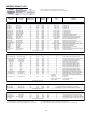
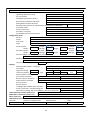
AQUA EFFICIENCY TAP WATER MODULES USER MANUAL GB Ver 3.1 2014/10/27 Table of contents Install the tap water module .................................................................................... Page 3 Hydraulic schematics Instantaneous / Semi-instantaneous.............................. Page 11 Main components ................................................................................................... Page 13 Electrical consumptions / Fuses ........................................................................... Page 14 Control box ............................................................................................................. Page 15 Terminal block location ......................................................................................... Page 15 Commissioning & maintenance instructions ....................................................... Page 18 Trouble Shooting ................................................................................................... Page 21 Controller components ......................................................................................... Page 22 Display / Keypad ..................................................................................................... Page 23 Hour & Date settings ............................................................................................. Page 24 Temperature setting ............................................................................................... Page 25 Technician Menu / Main Menu ............................................................................... Page 26 Material configuration menu ................................................................................ Page 26 S1 SENSOR Menu ................................................................................................. Page 27 S2 SENSOR Menu ................................................................................................... Page 27 DELTA T(S3-S2) Menu ........................................................................................... Page 27 S4 SENSOR Menu .................................................................................................. Page 28 Thermal treatment Menu ....................................................................................... Page 28 SAFETY function Menu ......................................................................................... Page 28 ECO & Booster functions ...................................................................................... Page 29 Fooling function Menu .......................................................................................... Page 29 PUMPS Menu .......................................................................................................... Page 29 230V TRIAC output Menu ....................................................................................... Page 30 Visualisation/Changes of I/O / Trending Menu ..................................................... Page 30 Alarm Menu / History .............................................................................................. Page 31 Warranty .................................................................................................................. Page 32 2 INSTALL AQUAEFFICIENCY UNIT Our tap water modules are designed for indoor installation in plant rooms where the ambient temperature should always be above 0°c. Max ambient temperature : 40°c. Max. hyg : 85% without condensation When handling the unit, make sure the actuator or piece of wire are not damaged or stressed. Dimensions and connection diameters are indicated on the following drawings : EFP 200 Series Instantaneous EFP 400 Series Instantaneous 3 EFP 600 Series Instantaneous EFP 200 Series SS/DS Semi-Instantaneous EFP 200 Series DD Semi-Instantaneous 4 EFP 400 Series SS/DS Semi-Instantaneous EFP 400 Series DD Semi-Instantaneous EFP 600/800 Series SS/DS Semi-Instantaneous 5 EFP 600/800 Series DD Semi-Instantaneous EFP 900 Series SS/DS Semi-Instantaneous EFP 900 Series DD Semi-Instantaneous 6 FUSION BONDED / COPPER BRAZED HEAT EXCHANGERS EFB/EFF 200 Series IS/ID Instantaneous EFB/EFF 400 Series IS/ID Instantaneous EFB/EFF 600 Series IS/ID Instantaneous 7 EFB/EFF 200 Series SS/DS Semi-Instantaneous EFB/EFF 200 Series DD Semi-Instantaneous EFB/EFF 400 Series SS/DS Semi-Instantaneous 8 EFB/EFF 400 Series DD Semi-Instantaneous EFB/EFF 600/800 Series SS/DS Semi-Instantaneous EFB/EFF 600/800 Series DD Semi-Instantaneous 9 EFB/EFF 900 Series SS/DS Semi-Instantaneous EFB/EFF 900 Series DD Semi-Instantaneous Factory fitting of a recirculation pump and a charging pump is not feasible.. INSTALLATION The primary water enters the modulating valve port and leaves through the fitting , Cold water enters at bottom part and leaves at the required temperature at high part , Pipe-up the pressure relief valve . The secondary circuit should be equipped with a recirculation or a charging pump (6), Modules suitable for 230V 1 phase / 50 Hz + Earth, Make sure power supply in the field corresponds to the above voltage, A fuse protection should be provided on site. Alarm indication: Volt Free Contacts (VFCs), 3 Amps maxi, each under 230 V. Minimum pressure/temperature on primary side : 1.0 barg/ 7°C, 1.5 barg / 100-110°C Maximum pressure/temperature on primary side : 10 barg /110°C Maximum pressure on secondary side : 10 barg / 110°C 10 HYDRAULIC SCHEMATICS The tap water modules should be installed according to the following schematics : INSTANTANEOUS : REP DESIGNATION A B CW PRV HE S5 Primary inlet Primary outlet Cold water inlet Pressure relief valve Heat Exchanger (FB/CB/PHE) Outdoor temperature sensor (optional) REP PR V S1 S2 S3 S4 DESIGNATION Recycling pump (option) Manual gate valve DHW temperature sensor (master) Secondary return temperature sensor Primary return temperature sensor Primary inlet temperature sensor (optional) Primary water storage version, to limit available instantaneous heat power. Whatever type, unit model and production type (Instantaneous or Semi Instantaneous), each pump (or pump motor when double ones) delivers 10% to 100% of the nominal primary pump signal and 25% to 100% of the nominal secondary pump signal, to stick to the actual demand. 11 SEMI INSTANTANEOUS UNITS : You must have PR flow rate < 60% PC flow rate Protect the storage tank by installing an added safety valve. Pressure gage=tank MAX working pressure and can be different from tap water module’s safety valve pressure gauge. It is to protect the storage vessel and NOT TWS. Type 1 Storage vessel connections (with inside injection pipe) You must have PR flow rate < 60% PC flow rate Protect the storage tank by installing an added safety valve. Pressure gage=tank MAX working pressure and can be different from tap water module’s safety valve pressure gauge. It is to protect the storage vessel and NOT TWS. Type 2 storage vessel connections (with feet) REP DESIGNATION REP DESIGNATION A B CW DC PC Primary Inlet Primary Outlet Cold water inlet Drain cock / flooding Charging pump PR V VR S1 S2 Installation recycling pump Manual gate valve Flow setting valve DHW temperature sensor (master) Secondary inlet temperature sensor PRV Pressure relief valve S3 Primary return temperature sensor Outdoor temperature sensor (optional) S4 Primary inlet temperature sensor (optional) S5 12 SOLARFLOW SCHEMATIC DIAGRAM REP DESIGNATION REP S1 S2 DHW temperature sensor (master) Secondary inlet temperature sensor Pt1 Sonde de température extérieure (optionnelle, pour application chauffage) S3 S4 13 DESIGNATION Primary return temperature sensor Primary inlet temperature sensor (optional) MAIN COMPONENTS* AND TECHNICAL DATA AQUA EFFICIENCY M6H PRODUCT RANGE & COMPONENTS 70 60 3 Different primary sides 4 different secondary sides 26-30 10 Primary Side AquaEfficiency M6H Flow DN 3 port Rate Return T° Valve (m3/h) 2.2 30 25 3.3 30 25 4.2 28 25 Secondary Side Pump type Pmax (W) Np Free P (Kpa) Magna 25-60 Magna 25-60 Magna 25-60 85 85 85 13 17 23 38 19 7 Flow Rate (m3/h) 1.7 2.6 3.4 HE DP (Kpa) Pump type Pmax (W) Free P (kPa) 11 9 9 Magna(N) 25-60 Magna(N) 25-60 Magna(N) 25-60 85 85 85 52 36 36 Series P (Kw) EFP 213 EFP 217 EFP 223 200 200 200 100 150 200 EFP EFP EFP EFP 425 429 435 449 400 400 400 400 250 300 350 400 5.5 6.7 7.5 8 27 30 29 26 32 32 32 32 Magna 40-100 Magna 40-100 Magna 40-100 Magna 40-100 180 180 180 180 25 29 35 49 32 13 6 5 4.3 5.2 6 6.9 9 13 12 8 Magna(N) 25-60 Magna(N) 25-60 Magna(N) 25-60 Magna(N) 25-60 85 85 85 85 29 17 13 10 EFP 637 EFP 645 600 600 450 510 10.2 11 31 30 40 40 Magna 40-120 Magna 40-120 450 450 37 45 40 36 7.7 8.8 15 15 Magna(N) 32-80 Magna(N) 32-80 140 140 18 10 EFP 849 EFP 855 800 800 550 600 12.1 13.2 30 30 40 40 Magna 40-120 Magna 40-120 450 450 49 55 29 20 9.5 10.3 15 14 Magna(N) 32-100 Magna(N) 32-100 180 180 11 6 EFP 961 EFP 977 EFP 997 900 900 900 640 700 750 14.1 14.7 15.1 30 28 26 40 40 40 Magna 40-120 Magna 40-120 Magna 40-120 450 450 450 61 77 97 10 7 7 11 12 12.9 14 11 11 Magna(N) 32-120 Magna(N) 32-120 Magna(N) 32-120 430 430 430 60 58 58 Pump type Pmax (W) Np Free P (Kpa) Magna 25-60 Magna 25-60 Magna 25-60 85 85 85 30 40 50 37 17 5 Flow Rate (m3/h) 1.7 2.6 3.3 AquaEfficiency CB/FB 52/60/76 H Secondary Side Primary Side Flow Return T° DN 3 port Rate (°C) Valve (m3/h) 2 25.7 25 3 26 25 3.8 26 25 HE DP (Kpa) Pump type Pmax (W) Free P (kPa) 13 12 16 Magna(N) 25-60 Magna(N) 25-60 Magna(N) 25-60 85 85 85 32 30 26 Series P (Kw) EFB/EFF 2 6030/5230 EFB/EFF 2 6040/5240 EFB/EFF 2 6050/5250 200 200 200 100 150 190 EFB/EFF 4 7640 EFB/EFF 4 7650 EFB/EFF 4 7660 400 400 400 240 340 390 5 7.1 8.1 28 28.5 28 32 32 32 Magna 40-100 Magna 40-100 Magna 40-100 180 180 180 40 50 60 51 17 5 4.1 5.8 6.7 6 8 8 Magna(N) 25-60 Magna(N) 25-60 Magna(N) 25-60 85 85 85 32 17 12 EFB/EFF 6 7670 600 500 11 29.5 40 Magna 40-120 450 70 48 8.6 9 Magna(N) 32-80 140 16 EFB/EFF 8 7680 800 600 13.2 30 40 Magna 40-120 450 80 27 10.3 10 Magna(N) 32-100 180 10 EFB/EFF 9 7690 EFB/EFF 9 76100 900 900 650 690 14.3 14.8 29.5 29 40 40 Magna 40-120 Magna 40-120 450 450 90 100 15 10 11.2 11.9 10 9 Magna(N) 32-120 Magna(N) 32-120 430 430 64 59 * As per version Electrical consumptions are given at nominal capacities. This allowing to calibrate fuse protections in the main heating room control box. Effective consumptions will be much more less most of the time, as pump(s) operate at variable speed. Please contact your Alfa Laval distributor for spare parts and note serial number and model designation: some components are specific to our tap water modules DECLARATION OF CONFORMITY This product is in compliance with following EEC norms: Pressure Equipment Directives (PED) 97/23/CE Low Voltage Directive (LVD) 73/23/EEC followed by 2006/95/EEC Following norms have been applied : EN 60335-1 partly EN 60204-1 partly 14 ELECTRICAL CONSUMPTIONS MAX Electrical consumptions INSTANTANEOUS 230V 1 Phase + Earth Common for PHE, FB and CB HE types MAX Electrical consumptions SEMI-INSTANTANEOUS 230V 1 Phase + Earth Common for PHE, FB and CB HE types Series Version Pump type Pmax (W)* I (A)* Series Version Primary Pump type Secondary Pump type Pmax (W)* I (A)* 200 200 IS ID Magna 25-60 2xMagna 25-60 100 185 1.1 1.7 200 200 200 SS DS DD Magna 25-60 2xMagna 25-60 2xMagna 25-60 Magna 25-60N Magna 25-60N 2xMagna 25-60N 185 270 270 1.1 2.3 2.3 400 400 IS ID Magna 40-100 2xMagna 40-100 195 375 1.75 3 600 600 IS ID Magna 40-120 2xMagna 40-120 465 915 2.5 4.5 400 400 400 SS DS DD Magna 40-100 2xMagna 40-100 2xMagna 40-100 Magna 25-60N Magna 25-60N 2xMagna 25-60N 265 460 460 2.35 3.6 3.6 800 800 IS ID Magna 40-120 2xMagna 40-120 465 915 2.5 4.5 600 600 600 SS DS DD Magna 40-120 2xMagna 40-120 2xMagna 40-120 Magna 32-80N 2xMagna 32-80N 2xMagna 32-80N 605 1055 1055 3.5 5.5 5.5 900 900 IS ID Magna 40-120 2xMagna 40-120 465 915 2.5 4.5 800 800 800 SS DS DD Magna 40-120 Magna 32-100N 2xMagna 40-120 Magna 32-100N 2xMagna 40-120 2xMagna 32-100N 645 1095 1095 3.75 5.75 5.75 900 900 900 SS DS DD Magna 40-120 Magna 32-120N 2xMagna 40-120 Magna 32-120N 2xMagna 40-120 2xMagna 32-120N 895 1345 1345 4.3 6.3 6.3 * Total max consumption including actuator + controller. 230V AC 50Hz+Earth power supply Read carefully controller’s instructions on next pages before servicing the unit. Power supply the control box 230V 50 Hz + Earth, using electric protection in the main electric power box. Micro 3000 box is a secondary control box. Human protections and protection against short circuits and over intensity must be installed in the main electric box. FUSES Only authorized people should operate on the unit. Cut off electrical supply of the unit before working on it. The power boards are fitted with a set of fuses to protect the different components against overload. Please refer to the chart below : Fuse FU1 FU2 FU3 FU4 FU5 Protection PUMP 1 PUMP 2 PUMP 3 PUMP 4 Power card Size 6.3 x 32 6.3 x 32 6.3 x 32 6.3 x 32 6.3 x 32 Rating 2,5 A 2,5 A 2,5 A 2,5 A 250 mA Voltage 250 V 250 V 250 V 250 V 250 V Extra fuses are included in the control box for quick servicing. WIRING ACTUATORS Following actuator’s brand and type, terminals labels are different and indicated here : Samson 5824/5825 : shunt between N and 12 terminal. 15 CONTROL BOX TERMINAL BLOCK LOCATION The schematics below show the general components’ implantation on the printed circuit board CY9_318. 230 volts terminal is on the bottom left side and Inputs/Outputs terminal on the bottom right side. MODBUS terminal 230 VOLTS TERMINAL SECTEUR 230 V MAINS Ph 4 5 6 7 8 9 10 11 12 13 14 15 SORTIE POMPE 1 SORTIE POMPE 2 SORTIE POMPE 3 SORTIE POMPE 4 Imax = 8A Imax = 8A Imax = 8A Imax = 8A POWER P1 POWER P2 POWER P3 POWER P4 N POMPE 1 / PUMP 1 IPSO 1 ON/OFF 0V 22 23 24 25 26 0/10V 27 49 50 51 52 53 IPSO 2 ON/OFF 0V POMPE 2 / PUMP 2 POMPE 3 / PUMP 3 IPSO 3 ON/OFF 0V 28 29 30 31 32 54 0/10V 0/10V 33 55 56 57 58 59 IPSO 4 ON/OFF 0V POMPE 4 / PUMP 4 0V 34 60 0/10V PT1 35 16 IN5 36 18 19 SERVO 230V Ph 61 62 63 PT2 IN6 64 65 20 21 DO9 - DO5 24Vac AO1 37 38 39 0V 16 17 CDE N 3 + 2 N 1 I/O TERMINAL 0V 40 66 DO6 24Vac AO4 0V 41 Ui1 42 0V 43 Ui2 44 0V 45 Ui3 46 0V 47 Ui4 48 67 68 69 70 71 72 73 74 75 0V 0V Ui5 0V Ui6 0V Bi1 0V Bi2 PUMPS’ NUMBER The pumps’ configuration & connections are factory made, but in case of servicing, you have to identify pumps: Codification Meaning EFxxxxxIS Instantaneous Single EFxxxxxID Instantaneous Double EFxxxxxSS Semi-instantaneous Single / Single EFxxxxxDS Semi-instantaneous Double / Single EFxxxxxDD Semi-instantaneous Double / Double Connected pump(s) P1 P1 + P2 P1 + P3 P1 + P2 + P3 P1 + P2 + P3 + P4 If you want to add a recycling pump (Instantaneous ONLY), this one should be connected to P3. PUMP TYPE : FIXED OR VARIABLE SPEED AquaEfficiency uses variable speed pumps. In the case you use or add a constant speed pump (Class A recycling pump for example), you have to configure the pump type on the power board by the mean of selector on the right side of the PCB as indicated on the picture: Pump No. Pump type selector. Left position=constant speed pump (= ). Right position=Variable speed pump ( =). If lit, the corresponding pump is energized PUMP WIRING We show here how to connect the primary pump P1 CONSTANT SPEED PUMP WIRING 4 230 V Ph 5 6 7 8 9 10 11 12 13 14 15 SORTIE POMPE 1 SORTIE POMPE 2 SORTIE POMPE 3 SORTIE POMPE 4 Imax = 8A Imax = 8A Imax = 8A Imax = 8A POWER P1 POWER P2 POWER P3 POWER P4 16 CDE N SECTEUR MAINS 3 17 18 19 SERVO 230V Ph + 2 20 21 N 1 DO9 - POMPE 1 / PUMP 1 0V IPSO 1 ON/OFF 22 23 24 25 26 0/10V 27 N N Ph IPSO CONTACT There is no polarity on ipsothermic contacts Whatever the application, never exceed 8A continuous load pumps (AC3 class) under 230V AC. If you use AC1 class load (Cos0.95), never exceed 20A under 230V AC VARIABLE SPEED PUMP WIRING Ph 230 V 4 5 6 7 8 9 10 11 12 13 14 15 17 SORTIE POMPE 1 SORTIE POMPE 2 SORTIE POMPE 3 SORTIE POMPE 4 Imax = 8A Imax = 8A Imax = 8A Imax = 8A POWER P1 POWER P2 POWER P3 POWER P4 16 CDE N SECTEUR MAINS 3 17 18 19 SERVO 230V Ph + 2 - 20 21 N 1 DO9 POMPE 1 / PUMP 1 IPSO 1 ON/OFF 0V 22 23 24 25 26 0/10V 27 N VARIABLE SPEED PUMP WIRING 4 230 V Ph 5 6 7 8 9 10 11 12 13 14 15 SORTIE POMPE 1 SORTIE POMPE 2 SORTIE POMPE 3 SORTIE POMPE 4 Imax = 8A Imax = 8A Imax = 8A Imax = 8A POWER P1 POWER P2 POWER P3 POWER P4 16 CDE N SECTEUR MAINS 3 17 18 19 SERVO 230V Ph + 2 - 20 21 N 1 DO9 POMPE 1 / PUMP 1 IPSO 1 ON/OFF 0V 22 23 24 25 26 0/10V 27 Ph N N IPSO CONTACT ON/OFF CONTACT P1 0-10V SIGNAL Whatever the application, never exceed 8A continuous load pumps (AC3 class) under 230V AC. If you use AC1 class load (Cos0.95), never exceed 20A under 230V AC There is no polarity on ipsothermic contacts 0 volt (terminal 26) to be connected to 0 volt (or ) of pump’s terminal 0-10 volts signal (terminal 27) to be connected to 0-10V signal input of pump’s terminal ACTUATOR WIRING ACTUATOR WIRING 24Vac AO1 38 39 0V 40 0-10V DC 24V AC 22VA max OR 24Vac AO1 38 39 0V 40 0-10V DC 24V AC 22VA max The 0V contact is common with 0-10V signal and 24V AC actuator power supply. Some actuators have 4 terminals to wire : 0 Volt 0-10 volts (signal) “Neutral” of 24V AC power supply “Phase” of 24V AC power supply In this case, just shunt the 0V and Neutral inside the actuator wiring box. SENSORS’WIRING Temperature sensors are real or simulated thanks to micro switches. The affected sensors are S1…S6 and Pt1 & Pt2. If a sensor is not present, corresponding micro switch must be “ON”. If the sensor is present and wired, put the micro switch on “OFF” position. S1 : Secondary outlet sensor (DHW) S2 : Secondary inlet sensor (CW/Recycling) S3 : Primary outlet sensor S4 : Primary inlet sensor (optional) S5 : Outdoor temp sensor (heating application only or AquaEfficiency combined with AlfaStore B unit) S1…S5 are NTC20k temperature sensors. 18 SOLARFLOW ONLY In the Solarflow application, an extra sensor Pt1 is needed. When Tpt1(Ts2+DTrecup min), the unit is activated and regulates like standard AquaEfficiency. If not, the unit is placed in standby mode : Primary pumps only are stopped and valve is closed until Tpt1 increases again. All other AquaEfficiency functions operational. 0V 34 Pt1 35 This mode is activated in the “Configuration Menu”, where you can also define +DTrecup min (5°C default value). Please refer to the Solar menu on next pages. Pt1000 Pt1 is a Pt1000 type temperature sensor. ALFASTORE A (ALFAPILOT ON/OFF) In this application, an extra sensor Pt1 is needed. When Tpt1(Ts2+DTrecup min), the function is activated and opens wide a second control valve wired on AO4 output, extra actuator. All other AquaEfficiency functions operational. This mode is activated in the “Configuration Menu”, where you can also define +DTrecup min (5°C default value). Please refer to the Solar menu on next pages. Pt1 is a Pt1000 type temperature sensor. ALFAPILOT (ALFASTORE B) In this application, 2 extra sensors Pt1 and Pt2 are needed. When Tpt1(Ts2+DTrecup min), the function is activated and opens a second control valve wired on AO4 output, extra actuator. The regulation is proportional at the opposite of AlfaStore A, and operates around a set point compared to the measured temperature on Pt2. All other AquaEfficiency functions are operational. This mode is activated in the “Configuration Menu”, where you can define many specific parameters. Please refer to the Solar menu on next pages. Pt1 and Pt2 are Pt1000 type temperature sensors. 19 230V TRIAC OUTPUT I BY-PASS function Some condensing boilers do not accept too low temperature returns or too big primary temperature differentials. AquaEfficiency primary outlet can be around 25°C minimum (during peak taping period especially). If primary inlet temperature is 70°C, that makes a Delta T=45°C. You have 2 solutions to heat up the primary return temperature if delta T is too high, considering the boiler : TRIAC 20 21 N 1- Install a mixing bottle before the AquaEfficiency primary circuit. In this case use a transfer pump between the boiler and the bottle, considering that its flow rate must be higher than the AquaEfficiency nominal flow rate. This to mix some primary inlet with the primary returns and then to increase the temperature. Such a solution is indicated in our flow charts. DO9 230 V 2- Install a by-pass before the unit with an electrical 230 Volts normally closed shutting component : electro valve 230V NC, small pump 230V 1A max, or 2 port valve 230V 3 steps signal with return to zero position in case of no power supply. AquaEfficiency is able to pilot this extra component help with an added primary inlet sensor, S4 and the wiring terminal as shown. The “230V Triac Menu” will then have to be configured (see later on). In operating mode, if delta T (S4-S3) is higher than a preset value (that you can change), the triac output is energized to give 230V between N and DO9 terminal, to pilot the by-pass component. Neutral to be connected on N (terminal 20) and phase on DO9 (terminal 21) II- 230V CLOCK PULSE FUNCTION To make another use of the 230V electrical output, you can configure it as a pulse function to activate shortly an electrical drain valve for example. In this configuration, you can program day, week or special days you want this to happen and the pulse duration (can be each Sunday at 10h00 for example and for 5 seconds). Please refer to the “230V Triac Menu” later on. RELAY 1 CONTACT WIRING (Affectation in Configuration sub menu) To be connected between IN5 and DO5 (36 & 37 terminals). This contact is normally open (NO). 0/10V 27 3 0V POMPE 3 / PUMP 3 IPSO 3 ON/OFF 0V 28 29 30 31 32 0/10V 33 0V 34 PT1 35 IN5 36 DO5 24Vac AO1 37 38 39 0V 40 0V 41 Ui1 42 0V 43 Ui2 44 0V 45 Ui3 46 0V 47 Ui4 48 If you use 230V phase through this contact, do not exceed 2A load. If a default occurs, it closes. 54 0/10V 55 56 57 58 59 IPSO 4 ON/OFF 0V POMPE 4 / PUMP 4 60 0/10V 61 62 63 64 65 66 67 68 69 70 71 72 73 74 75 RELAY 2 CONTACT WIRING (Affectation in Configuration sub menu) To be connected between IN6 and DO6 (63 & 64 terminals). This contact is normally open (NO) 0V PT2 IN6 DO6 24Vac AO4 63 64 IN6 DO6 0V 0V Ui5 0V Ui6 0V Bi1 0V Bi2 If you use 230V phase through this contact, do not exceed 2A load. . If a default occurs, it closes. REMOTE CONTROL The whole unit can be started or stopped remotely help with a volt free contact connected between BI1 and 0V (72 & 73 terminals). 72 73 0V Bi1 DO NOT power supply this contact! Volt free contact only When contact is open, the unit operates normally. If it is closed, primary and secondary pump(s) is(are) stopped and valve(s) get a 0% (0 volt) signal. Controller display remains activated 20 COMMISSIONING The installation and use instructions should be respected, and the factory settings be unchanged. Rince the pipe works before piping the tap water module up. Pipe works may contain solid particles that could block or prevent the 3 or 4 port modulating valve from operating normally, Pipe the primary and the secondary of the module, Fill-up both sides progressively with water, Purge air at high parts, Purge all the pump bodies, Switch the power on, Check controller setting and enable the required functions, MAINTENANCE Our tap water modules do not require frequent inspections or dismantling. The frequency of the inspections depends on the water hardness, temperature and consumption (Flow rate). Scaling of the secondary side will be evidenced by : A high pressure drop on the secondary side of the exchanger, Improper temperature range on the secondary side of the exchanger, Low temperature difference between inlet and outlet on the primary side of the exchanger when the control valve is fully open, A warning from the controller if the unit is equipped with the scaling control or CIP option (F/B series only). Disassembling of the exchanger can be done very quickly according to the following procedure: Maintenance should be operated by qualified and authorized person only Risk of electric shocks: Cut off electrical supply of the unit Burning risk: let the exchanger cool down until a temperature of 40°c approximately is reached on both sides Then, isolate primary and secondary hydraulic circuits, Open the purge cocks to drop the internal pressure of each sides, PLATE HEAT EXCHANGERS ( P Series) Measure the distance between the two frames of the exchanger (Plate pack thickness) and note it down, Open the exchanger by unscrewing and removing the frame compression bolts, To avoid injuries owing to sharp edges, protective gloves should always be worn when handling plates and protective sheets (like the ones for insulation). Remove the plates without damaging the gaskets and note their orientation and position, Clean the plates using a soft plastic brush and water or a solution of diluted acid in accordance with PHE plate general cleaning instructions. DO NOT USE hydrochloric acid or any acid that could corrode stainless steel plates DO NOT USE water with more than 330 ppm Cl when making a cleaning solution. Nitric (for calcium carbonate), sulfamic (for calcium sulphate) or citric (for silt) acids can be used. Concentration should not exceed 4% at 60°c. Protective gloves and glasses should always be worn while these operations. Carefully rince the plates with clean water after cleaning. Re mount the plates in the same order and at the same position they were before, Screw the frames to the same distance they were before (Plate pack thickness dimension), It is also important to clean the control sensor pocket. For further informations please refer to Alfa Laval Instruction Manual Ref. 1644725-01 21 FUSIONNED BONDED OR BRASED (F/B Series) For these heat exchangers, use the Alfa Laval CIP kit, with compatible cleaning products. Be sure the heat exchanger has been insulated, using primary and secondary gate valves Unscrew the specific caps located at the opposite of primary and secondary ports. Retrieve top and bottom clips to remove insulation To process cleaning, use CIP connections 3/4" (CB60/FB52) or 1”1/2 (CB/FB76). Remove connection caps and plug cleaning system We recommend you the use of Alfa Laval CIP 20 type with specific cleaning liquid. Different types are available, especially for fooling or lime scaling : AlfaPhos for example. Use a neutralization solution before cleaning with clear water (AlfaNeutra for example). Circulators and pumps do not require any specific maintenance. Check annually that no leaks are detected level with the rotative seal when external motor pumps are used. Measure electric motor current drawn. The control valves do not require any specific maintenance. Annually check that no leaks are detected level with the sliding rod seal package. The electrical panel does not require any specific maintenance. Annually check electrical connection tightenings. 22 TROUBLE SHOOTING FINDINGS Pump not operating PROBABLE CAUSES Locked rotor or damaged Corresponding led is not lit Pump relay damaged Pump protection fuse blown High Alarm condition detected No voltage to control board terminals No voltage to pump motor terminals Low temp alarm condition Controller improperly set Primary pump stopped Too low primary temperature Too high tap water flow rate (SI) Modulating valve does not operate High alarm condition detected Set point too high 3 way valve remains closed Damaged or broken actuator Broken or improperly tightened coupling Valve blocked No signal from the controller Supply wires improperly tightened Actuator stroke restricted Charging pump stopped (SI versions) Low recirculation flow rate (I versions) Alarm differential too low Modulating valve not closing Too much differential of pressure across the modulating valve Correct temperatures across Excessive exchanger scaling at the exchanger not obtained. the primary or secondary side Valve and pumps operating satisfactorily Primary pipe work obstructed or strainer upstream clogged Isolation valve closed Air presence in the primary Excessive pressure drops Temperature does not Recirculation flow rate exceeds increase in the buffer vessel charging flow rate. and the tap water value is correct. 23 REMEDIES Force to rotate. Replace if required Replace Power Board Replace Power Board Check then replace if necessary Clear alarm then reset system Check power supply cable and fuses, Check protection fuse on main board, cable condition and connections Contact After Sales Service See above Check for a closed valve in the primary Reduce buffer vessel charging flow rate Refer to next box below Test then replace if necessary Check then replace if necessary Replace Check then replace if necessary Check wires, re-tighten connections Dismount then clean the valve Refer to ‘’Pump not operating’’ above Check and fix problem Check and set the controller Refer to previous box above Check the way the TWM is pipedup. Mixing arrangement should be used Open and clean the exchanger according to cleaning instructions Inspect primary pipe work. Clean strainer on the primary side Open isolation valves Purge. Check no high parts where air could be trapped exist Check pipe size is suitable for nominal flow rate Check and measure charging and recirculation flow rates. Adjust when necessary. Recirculation FR < 0.6 x Charging FR CONTROLLER COMPONENTS Following components are located behind the front metal plate. If you need to remove it and access internal components, remove the 4 front screws. The control system consists in three main components: Power board CY9-318, Micro 3000 Controller, Main switch. KEYPAD / DISPLAY Bipolar Main Switch POWER BOARD MICRO 3000 Wires terminal DIN rail for controller support 24 KEYPAD / DISPLAY Turn / Push button Status led KEY FUNCTION Rotative button to scroll into menus and to change values. To activate the line or parameter it is on, just press the button. If you have access to the submenu/parameter, it will be black grounded and then you can press the button to access the sub-menu/change parameter. Otherwise, you just pass on it. At the opposite, to exit press this key To access to the technician menu. REQUIRES A PASSWORD Press at any time to come back to home screen Alarm menu Not used Not used Relay 1 activated (assignment in configuration sub-menu) Relay 2 activated (assignment in configuration sub-menu) Data transmission in COM mode Data reception in COM mode Alarm light Controller energized HOME SCREEN The display shows the following information : Access level. locked=restraint Key=total (3333) Date / Hour The program is running DHW temperature DHW Set point Access to other menus by rolling the wheel. 25 COMMAND SYMBOLS Auto Datapoint is in automatic operation and can be switched into manual operation. Manual Datapoint in manual operation and can be switched into automatic operation. Today function Datapoint value can be overridden for a particular time period within the next 24 hours. Datapoint must have a daily time program assigned. Time Program Datapoint has a daily time program assigned. Daily time program can be selected and edited. Edit Item (datapoint, time program etc.) can be edited. Add Item (datapoint, time program etc.) can be added to a list e.g.a datapoint can be put to a list of trended datapoints. Deleted Item can be deleted Enable/disable Checked: item is enabled Unchecked: item is disabled 26 DATE & TIME SET ACTION DISPLAY Rotate the wheel counterclockwise up to the 1rst display line. Then press the wheel. The screen looks like this : Date setting Press the wheel to change the year that is flashing now Increase or decrease the value by rotation. When done, press the wheel again to set next parameter Enter Do the same for month and day (push) Time setting Set hour then minutes Date Format Choose between yyyy-mm-dd, mm-dd-yyyy, dd-mm-yyyy, dd.mm.yyyy, dd/mm/yyyy Daylight Saving Time Hour change between winter/summertime is automatic, but you can redefine and change dates, or disable this function. SAVE MODIFICATIONS Once you have validated a setting by pressing the wheel, changes are updated. You can press + or to go back to home screen 27 - CHANGING THE TEMPERATURE(S)’ SETPOINT(S) You can set : Identical / Different daily temperatures (unlimited periods possible), Holidays’ periods (useful for school for example) Special days (holidays’ periods for example) during the year with specific set points ACTION DISPLAY Access to the main menu These settings are available for both access levels Press to return to home screen. Then access to the set point time program by turning the wheel clockwise until accessing to the S1 Menu line as shown here : Then press the wheel to enter this menu Now focus on the clock logo and press on it Other parameters are not accessible from end user level To access them, you must have technician access level . Please refer to next pages for other settings. Define for each day of the week if it is Week temperature or Week end temperature with another value By default, week-end values are deactivated and then set points are the same for all week days. To change time schedule, rotate the wheel until reaching the time/temp settings Default temperatures By default, DHW set point on S1 is constantly set at 60°C. You can add extra temperature set points at different times of the day (ex : 55°C at 10h00). These changes will be reported for all days of the week, excluding “week end” temperatures if existing. Example : You want to reduce S1 set point at 55°C at 23h00 instead of 60°C at 22h00. nd Select the 2 line and press the wheel. Now change the time and temperature set point like this : If you want to delete this extra temperature program, click on . Otherwise, keep it and press on to come back one menu level up. You now have 2 different temperature set points at different times. You can add as many time/set point as you want by pressing on and delete them help with Special days From the schedule menu, place the cursor on “Spcl.Days” as shown : You then have 3 possible choices Annual=Holidays period where you have to specify : Beginning/End/DHW set point (application : schools, offices…) Bank Holiday = special days during the year where set points can be different (ex : Christmas, new year…) Daily programs = Particular days where you want to change the temperature set point. Quick temperature change You can quickly define a “one time” temperature change. When the change period will have expired, temperature set point will come back to standard time schedule program. Select this icon and click on Then define starting and ending time, and the temperature set point value. Temperatures setting must be in accordance with country’s legislation (e.g EN, ISO….norms or recommandations). 28 TECHNICIAN MENU (both access levels) To get total access level, it is necessary to enter the password. This is how to do : **** Indicates total access level 3333 To access to technician access level and be able to change values greyed, you have to place the cursor on the lock (in main screen or in any sub menu) and enter 3333 code MAIN MENU Main Menu CONFIGURATION SUB-MENU This menu is not accessible from end-user access level. You must enter the “3333” code You can activate connected sensors. S1, S2, S3 are present on standard AquaEfficiency and SolarFlow units. Only S4 is optional. If you use the control box as an AlfaPilot in stand alone mode (no AquaEfficiency connected), then you can disable S1 and S2. Nethertheless, this is not mandatory. Display S1 Activated S2 Activated S3 Activated S4 Activated Activer loi CH S5 Cooling Mode AO1 P1P2 Nbr of Pumps P3P4 Nbr of Pumps ModBus Factor Keep 1 Set to 1 Set to 1 Keep 0 Keep 0 Keep 0 0/1/2 0/1/2 1 Default Value Relay 1 Function 1 Relay 2 Function 2 T_Secondary_Out S1_PID_Setpoint T_Secondary_Inlet T_Primary_Outlet T_Primary_Inlet T_Renewable1 T_Renewable2 T_Outdoor Configuration S1 Menu Sec.Outlet S2 Menu Sec.Inlet Delta T (S3-S2) S4 Menu Prim Inlet S5 Menu Outdoor T Thermal Treatment SAFETY Function Eco Booster Fcts Fooling Function Pumps Menu Solar Menu Aquaprot_Heating 230V triac Menu Auto Test Clear Alarm(s) Description 0/1 Not activated / Activated sensor 0/1 Not activated / Activated sensor 0/1 Not activated / Activated sensor 0/1 Not activated / Activated sensor 0/1 Not activated / Activated sensor 0=Heating Mode / 1=Cooling Mode 0/1/2 as per equipement 0/1/2 as per equipement 1..100 to display decimals on modbus values 1=No decimal (integer values, ex : 58°C) 10=0.1 decimals (ex : 58.3°C) 100=0.01 decimals (ex : 58.36°C) 0=No action 1=General Default (GD) 2=High temp Alarm (HA) 3=Eco function (E) 4=Booster function (B) 5=Thermal Treatment (TT) 6=Pump Fault (PF) 29 Read Only Read Only Read Only Read Only Read Only Read Only Read Only Read Only Sub Menu Sub Menu Sub Menu Sub Menu Sub Menu Sub Menu Sub Menu Sub Menu Sub Menu Sub Menu Sub Menu Sub Menu N/A Sub Menu Sub Menu Sub Menu Renewable Config 0 APilot Inverted 0 7=Tank loaded (TL) 0=Not used 1=SolarFlow (SF) 2=AlfaStore A (AA) (also called AlfaPilot On/Off) 3=AlfaPilot (AP) (also labelled AlfaStore B) 0/1 Allows to reverse the Valve #2 signal for AlfaPilot (AO4) If AlfaPilot mode is used, set to « 1 », due to standard component used PC distrib i i/E : internal / External for Modbus use ALAFALAVAL_Version xx Software version If S5 Active heating=1, the secondary outlet temperature set point (called “S1_PID_Setpoint” in the main list) will be calculated by an heat curve, function of the outdoor temperature (S5 sensor needed). See later on for the heat curve parameters. If S5_Active_Heating =1, the heating mode is activated, with heat curve for calculated output setpoint on S1 Both relays 1 and 2 are programmable: you can choose their affectation Last 3 lines define the renewable mode. You can find back these settings in the solar menu for reading only. 30 SENSOR 1 MENU As S1 is the master sensor, you find into this menu main control loop parameters VALUES'CHANGES IF TECHNICIAN LEVEL S1 Menu Sec.Outlet SP_T_Sec_Outlet + 60°C DHW Setpoint Change value in clock program() or 1 time change() Delta T S1 HiAlm 10°C 0-50 High Temperature Alarm if Ts1 SP_T_Sec_Outlet+Delta Ts1 HiAlm High T Alarm Tempo 1 min 0-60 High temp alarm is effective after this temporisation 0 0/1 0=MANUAL alarm clear / 1=AUTO alarm clear Off/On Put ON to clear an high temp alarm, then put Off In general 20<P<40°C Negative values in cooling P to be less reactive P to be more reactive (be carreful of "pumping" effect) 50 0-120 I to be less reactive I to be more reactive (be carreful of "pumping" effect) D Main Derivative 2 sec 0-50 Séq_Vanne_Vit N/A Internal settings High Alarm Auto Reset High_Alm_Reset P_Main Prop Band Off 20 (-100 à 100) I Main Integral SENSOR 2 MENU, SECONDARY INLET TEMPERATURE SENSOR You find here anticipation parameters when temperature suddenly increases or decreases. Action is signal change on control valve and primary pump(s) speed. The Delta T (S1-S2) function is for variable charging pump units only. When S2 approaches S1 value, an auxiliary control loop reduces charging pump speed down to a minimum settable value (see below); At the opposite, if temperature on S2 decreases, the pump speed will increase. TECHNICIAN LEVEL ONLY S2 Menu Sec Inlet Delta T (S1-S2) vit P3P4 8°C 3..20 P Band DT(S1-S2) 5°C 4..20 DZ_GS2 enk/s 0.5 Do not change Inverted output 0 Set 1 if cooling mode Min Speed P3P4 25 20 - 100% Secondary charging Pump speed regulation approaching the temperature setpoint. Extra electrical energy savings by keeping minimum speed for recycling loop when tank is loaded. Anticipation on ctrl valve+prim.pump signal, depending of temperature gradient on S2 (ex: quick temp. Loss if tappping =open ctrl valve + accelerate primary pump to save HE+S1 time cst) reverse anticipation action (for cooling mode only) Minimal speed if DHW setpoint almost reached (secondary charging pumps only) To disable the gradient function, disable S2 in the “Configuration” menu. VALUES'CHANGES IF TECHNICIAN LEVEL DELTA T (S3-S2) MENU This function limits the primary return temperature, acting on primary pump signal (speed). It acts like a setting valve, limiting the primary flow rate. Delta T (S3-S2) Added control loop on delta T Primary Outlet-Secondary Inlet. Action on primary pump speed only Delta T(S3-S2) 20 K 0-100°C (keep around 25) DT ctrl loop to influence primary return temp. If you want a small action on DT ctrl loop, set >30 BP Delta T S3-S2 Intégrale DT S3-S2 10 K 2 sec Do not change Do not change Value 0-100°C. Big value=Low influence Value 0-50. Big value=Low influence 0/1 1=Activated function/ 0=Disabled function It is a copy from Configuration Menu S3 activated 1 If cooling mode, disable the function by inputting 0 on « S3 activated » line. 31 S4 MENU PRIMARY INLET SENSOR TECHNICIAN LEVEL ONLY TO ACCESS THIS MENU If a sensor S4 is connected at the primary inlet, another anticipation function can be activated. When temperature suddenly increases or decreases, an action signal is sent to control valve and primary pump(s) speed. S4 Menu Prim Inlet DZ-GS4 en k/s 0.5 Inverted output Anticipation on ctrl valve+prim.pump signal, depending of temperature gradient on S4 (ex: boiler temp. Loss if tappping =open ctrl valve + accelerate primary pump to save HE+S1 time cst) reverse anticipation action (for cooling mode only) Do not change 0 Set 1 if cooling mode THERMAL TREATMENT FUNCTION See explanations bellow VALUES'CHANGES IF TECHNICIAN LEVEL THERMAL TREATMENT MENU This function is activated as per a time program. It is disabled by default The user has to define either a 1 sensor mode (fixed duration as per Therm.Tr duration' parameter) OR 2 sensors'mode (variable total duration) until TT.Max try time During this time interval the effective treatment starts as soon as DeltaT (S1-S2)<='Delta T S1S2 ThTr' parameter value ThTr_Setpoint 70°C TrTh_Activated + Off Sensor_Nbr ThermTr Duration Fixed duration (1 sensor) TT Max try time DeltaT S1S2 ThTr Inhibition time Usual value Off/On Enable or Disable the function as per clock program Auto Auto/1 sensor/2 sensors 1 min 0 1 min 7°C 30 min 1-240 min (4 hours max) 0/1 1-240 min (4 hours max) 1 - 20°C 0-180 (0 à 3 hours) Adjust value according to the installation + buffer vessel capacity IF Auto or 2 sensors mode If during TT Max try time, delta T (S1-S2) is higher than preset value ->thermal treatment failure High temp alarm inhibition time aftre thermal treatment Thermal treatment activates by defining a clock setting (On or Off) SAFETY FUNCTION Note that in case of high temperature alarm, primary pump(s) are stopped VALUES'CHANGE IF TECHNICIAN LEVEL SAFETY Function This function activates the 4 pumps' power relays at the same time without considering ipsothermic contacts' inputs. Furthermore, you can define the voltage sent to the 0-10V pumps'signal, then to choose pumps'speed (for variable speed pumps) You can enble this function from base access level. SAFETY_Speed SAFETY FCT 75% Off 5-100% Off/On In case of high temperature alarm on S1, primary pump(s) is(are) stopped, even if the function is activated. 32 ECO & BOOSTER FUNCTIONS VALUES'CHANGE IF TECHNICIAN LEVEL Eco Booster Fcts You can activate 1 or the other function or both at the same time ECO : Activates a temporisation as soon as valve is closed less than hystérésis valve' and DHW is higher than Setpoint - "Eco Hysteresis" parameter After this temporisation, the start/stop contact of primary variable speed pumps OR primary cst speed pumps' power supply is stopped. Booster : If DHW temperature is dropping down faster than "Booster Gradiant", the second primary pump (if existing) is energized, to increase the primary flow rate. Function stops when DHW temperature is back to the setpoint value and after "Booster Tempo" parameter 1:Eco 2:Boo 3:EcoB 0 None/Eco/Booster/Eco+Booster Fct_Selection Normal Normal/Eco/Boost/EcoBoost Eco Delay 5 min 1-30 min Eco Hysteresis 5°C 1-20°C Valve Hyseteresis 4% 1-10% Booster Delay 2 sec 0-30 sec Booster Gradient 1°C/s 1 à 5°C/sec S5 MENU- OUTDOOR TEMPERATURE This sub-menu allows to adjust the heat curve parameters : slope + ambient temperature influence on clock program. To be effective, you MUST have selected S5 Active Heating=1 in the Configuration menu. Access this sub-menu to adjust requested ambient temperature if necessary (it is the inside ambient temperature set point). You can check/change this by clicking on the clock logo This temperature will apply a set point correction to the heating curve. 20°C ambient is the reference temperature, where no correction occurs (see diagram below). By default it is set to 20°C from 6h00 (am) to 22h00 (10 pm)and then to 15°C from 22h00 (10 pm) to 6h00 the next day. If you want to change this time program, please refer to “HOW TO CHANGE THE TEMPERATURE(S)’ SETPOINT(S)” pages before. On next lines : Do not change the heat curve curvature (factory setting) You can adjust heat curve slope. Default value=1.6 (see diagram below) meaning : If -20°C outdoor temperature, Calculated setpoint≈85°C If +20°C outdoor temperature, calculated set point=20°C By example, If you want 90°C calculated set point by -20°C outdoor, set to ≈1.8 Now if you set at this time an ambient temperature at 15°C, the set point will be decreased to ≈87°C If you don’t use an outdoor temperature sensor, DO NOT FORGET TO SET “S5 Active Heating”=0 in the configuration menu, to allow the time scheduled set point (clock program) on S1. 33 As a reminder VALUES'CHANGE IF TECHNICIAN LEVEL FOOLING FUNCTION Fooling Function Activates an alarm if heat exchanger is considered fooled/lime scaled Fooling alm activ Fooling_alarm SP_Fooling 0 Normal/Default 65°C 0/1 0=Disabled / 1=Enabled READ ONLY Depends of HE type + Primary temerature inlet 60-80 PUMPS’MENU Pumps Menu P12 Diff.work time VALUES'CHANGE IF TECHNICIAN LEVEL P12 Permut.Type P12 Permut.Period P12 Permutation day P12 Permutation Hour P1P2 Superposition P34 Diff.work time P34 Permut.Type P34 Permut.Period P34 Permutation day P34 Permutation Hour P3P4 Superposition Pump_Fault_Reset 100 hrs 2 0 1 10h00 pm 6 100 hrs 2 0 1 10h00 pm 6 Off 1 - 1000 hours 0=Fixed time 1=Fixed time+ diff.work time 2=Immediatly after Diff.hrs P1 or P2 Working time See P12 Permut Hour If diff reached at this time, pump shift Don't care of permutation day+hour 0=None 1=Daily 2=Weekly 3=Monthly From 1st to 31st 00h00 - 23h59 (11h59 pm) 0-10 seconds Time to start P2(P1) before stopping P1(P2), to let the other pump start 1 - 1000 hours 0=Fixed time 1=Fixed time+ diff.work time 2=Immediatly after Diff.hrs P1 or P2 Working time See P12 Permut Hour If diff reached at this time, pump shift Don't care of permutation day+hour 0=None 1=Daily 2=Weekly 3=Monthly From 1st to 31st 00h00 - 23h59 (11h59 pm) 0-10 seconds Off/On Time to start P2(P1) before stopping P1(P2), to let the other pump start To clear a pump default, set to On, then Off Copy from the Clear alarm(s) menu 34 SOLAR MENU AquaEfficiency can be coupled with a SolarFlow or AlfaPilot working mode, allowing to take benefit of a solar energy with primary storage tank installation or alternative energy recovering installation. This using the same control box. The Micro 3000 combined with extra sensors can pilot a second 0-10V signal valve actuator, allowing to direct the outlet primary flow towards the primary storage vessel or towards the boiler (or heat generator). This distribution can be binary (open OR closed valve) in AlfaStore A configuration or proportional in AlfaStore B (=AlfaPilot) configuration. Note that AlfaStore A needs 1 extra sensor (Renewable1) and AlfaStore B needs 2 extra sensors (Renewable1+2) + optionally outdoor temperature sensor S5. VALUES'CHANGE IF TECHNICIAN LEVEL Solar Menu Covers multiple systems'configurations : Solar Flow AlfaStore A / AquaEfficiency + AlfaStore A AlfaStore B / AquaEfficiency + AlfaStore B Solar_Option Store B Inverted DT Récup Min No Option Off 5 No/SolarFlow/AlfaStoreA/B Config selection Off/On Depending of used valve type, it is sometimes necessary to invert the opening/closing travel. AlfaStore B=On -50 à +50 Use a negative value for a cooling mode Heating mode=Positive value (5-50°C) Distrib_Setpoint + 65/70°C Clock Progr.+1 time progr. For AlfaStore B, setpoint relative to Srenewable2(Pt2) and regulation around this setpoint via AO4 signal output (Valve No.2) PC_Distrib_Com PC_Distrib_distant Internal 65°C internal/external INTERNAL Solar Flow Only An added sensor Pt1 is necessary and will have to be placed before the primary inlet, in a primary storage buffer vessel (solar for example) In this mode, the unit will be placed in stand by (valve closed+pump stopped) until Pt1>=S2+DT Recup_Min When primary temperature is hot enough, the unit will be started normally and will regulate on secondary outlet temperature, S1 AlfaStore A Only An added on/off control valve (Valve No.2 wired on AO4) associated to S3 and Pt1 sensors allows the alfaStore A mode An added sensor Pt1 is necessary and will have to be placed before the primary inlet, in a primary storage buffer vessel (solar for example) As soon as S3>(Pt1+DT Recup_Min), valve 2 wide opens (continuous 10 volts signal), diverting the primary return flow towards primary vessel and then to send hot water towards the generator (boiler for example) to reduce energy consumption AlfaStore B Only An added control valve (Valve No.2 wired on AO4) associated to S3, Pt1 and Pt2 sensors allows the alfaStore B mode Added sensor Pt1 is necessary and will have to be placed before the primary inlet, in a primary storage buffer vessel (solar for example). Pt2 on the generator (boiler) inlet As soon as S3>(Pt1+DT Recup_Min), valve 2 regulates proportionnaly around Distrib_Setpoint If an outdoor sensor is connected on S5 input, Distrib_Setpoint value can be higher, due to heat curve result. You don't have to activate S5 in the "Configuration" Menu. 230V TRIAC MENU VALUES'CHANGE IF TECHNICIAN LEVEL 2 different Operating modes : If Multi P is On, you must set ByPass S4S3 to Off. If Multi P is Off, you can set ByPass S4S3 to On 230V TRIAC Menu This menu allows to use Triac output in 2 different ways (no cumulable) 1- Clock pulse, using time program. Pulse duration settable 2- Energise a bypass component if delta T (S4-S3)>set value Both functions can not be combined Multi P Pulse Duration Off 5 sec Off/On Clock program 1-3600 Bypass S4S3 DeltaT Bypass Off 30°C Off/On 5-50 Pulse(s) function OR ByPass Function 35 AUTOTEST MENU This sub-menu allows to test analogic and digital outputs. It is possible to run an automatic sequence or to test manually each output individually. In case of Auto test (automatic sequence), it is possible to reduce or increase tests’ temporizations. Pump, valve and relays test times can be adjusted individually. The time test value will impact on the total auto test time sequence. AutoTest VALUES'CHANGE IF TECHNICIAN LEVEL This menu allows to start an autotest that will activate binary and analogic outputs, to activate valves, pumps, relays, 230V triac It is also possible to read/write these different values manually on following lines Start AutoTest Pump time test Valve time test Alarm time test Cmd_P1 Cmd_P2 Speed_P1P2 Cmd_P3 Cmd_P4 Speed_P3P4 High_Temp_Alarm Main_Alarm Triac_Output Valve signal Valve2 signal 3 Pts valve signal 0 16 sec 16 sec 5 On/Off Off/On xx % On/Off Off/On xx % Off Off Off xx % xx % xx % 0/1 1-60 sec 1-60 sec 1-60 sec Set 1 to start autotest. When finished, value is back to zero Temporisations to adjust test duration 0-100 % 0-100 % On/Off On/Off On/Off 0-100 % 0-100 % 0-100 % Individual output reading / writing Autotest Closing Valves 1,2 and 3 points Stop 4 pumps (Off+0 volt) Pump 1 starts Signal at 50% Pump time test Valve 2 (AO4) 50% Valve 1 closes Valve time test Pump 2 starts Signal at 50% Pump time test 3 Pts valve opens Vanne 2 closes Valve time test Pump 3 starts Signal at 50% Pump time test 230V triac pulse Valve 3pts closes Alarm time test Pump 4 starts Signal at 50% Main alarm relay activated DO5 Pump time test Valve1(AO1) Vannes opens Signal at 50% Alarm time HighT relay activated test DO6 MODIFICATION POSSIBLE SI NIVEAU ACCESS TECHNICIEN CLEAR ALARM(S) MENU Clear Alarm(s) This menu allows to clear alarm(s) High_Alm_Reset Off Off/On Put On to clear alarm, then put Off Pump-Fault_Reset Off Off/On Put On to clear alarm, then put Off CHANGE PASSWORD If you want to change the actual password, do not forget to remember it, by a way or another. If lost, you can’t access to the technician level and only the S1 temperature setpoint can be changed. All other parameters are then either read only, or hidden (configuration menu for example). Note that to change the password, you must already have the technician level (Level 3). If you don’t have Press on “Login Installer” before and enter the current password. Press key to access to Service Menu, go to “Login Installer” line then enter the password if not done before accessing this menu then press the wheel to validate Click on “Change Password” then Level 2 password is not use in the program. Go directly to Level 3 line and then click on the password to change it 36 SERVICE MENU OPERATING HOURS You can check operating hours of some parameters. Press key to access to Service Menu, then click on “Continue” Select “Operating Hours” menu st If it is the 1 time you access to this menu, the list is empty. Otherwise, you will read already selected variables. To add a variable you want to trend, click on logo Then, select in the list the points you want to trend. See the points’ list in the following table Example : We want to record the primary pump 1 operating hours. We will select “Cmd_P1” into the list and click on it with the wheel. Then do not forget to tick it, otherwise the point won’t be in the list When you go back in the menu ( key), you can now see the list with “Cmd_P1” parameter, and on the right side, the operating hours. If you want more details, click on this line to make appear another screen Here you can read that P1 has been operating less than 1 hour, has been switched 1 time and is actually On. Proceed the same way to add extra variables. Variables’ list : Name Cmd_Distant Therm_Protec P1 Therm_Protec P2 Therm_Protec P3 Therm_Protec P4 Cmd_P1 Cmd_P2 Cmd_P3 Cmd_P4 Eco Booster High_Temp_Alarm Main_Alarm Triac_Output AFF_leg_active Multi_P SAFETY_FCT Tank load ThTr_Activated Description Binary input (VFC) to remotely Start/Stop the unit Ipsothermic input from P1 pump Ipsothermic input from P2 pump Ipsothermic input from P3 pump Ipsothermic input from P4 pump P1 command. 1=On / 0=Off. It is the Start/Stop input of the pump P2 command. 1=On / 0=Off. It is the Start/Stop input of the pump P3 command. 1=On / 0=Off. It is the Start/Stop input of the pump P4 command. 1=On / 0=Off. It is the Start/Stop input of the pump Function Eco activated Functyion Booster activated High temperature alarm on S1 sensor General Alarm 230v Triac output state. Thermal treatment activated 230V Triac pulse The safety function state Tank loaded Thermal treatment running 37 TRENDING You can record a lot of different variables listed in the table below. It can be temperatures’ measurement, valves or pumps’ signals, ipsothermic contacts, alarms, thermal treatments…. Press key to access to Service Menu, then click on “Continue” Select “Trending” menu Then this click on line st If it is the 1 time you access to this menu, the list is empty. Otherwise, you will read already selected variables. To add a variable you want to trend, click on logo Then, select in the list the points you want to trend. See the points’ list in the following table Example : We want to record the Secondary outlet temperature (please refer to table below). We select S1 into the list. Go to “S1” and click on it with the wheel. Then validate the point recording by ticking it (otherwise the point is in the list but is not recorded) There are 2 ways to record 1- Record only on temperature change (recommended method). This saves memory and allows a longer sampling period compared to method 2. Select the record hysteresis. In our case, we want to record every 1°C temperature change. You can change the hysteresis value by clicking on it. 2- Record on a time base, whatever the temperature changes or not. Note that this method consumes memory, especially if you select a low time base. Here we have selected a 10 minutes time base recording (1 record every 10 minutes). If you to use method 1, set “Trend cycle” to zero. If you want to use method 2, set “Trend Hyst” to zero. DISPLAY TREND BUFFER Press key to access to Service Menu, then click on “Continue” Select “Trending” menu Then this click on “Display Trend Buffer” line Select the variable you want to read (S1 in our case) You can read Date/Time and number of records actually in memory Click on it Then you can read Date, Time and the value at this moment (we are pointing here st S1=58°C on 21 of September at 14h22). 38 Display Trend buffer Points in trend You can select variables to trend (temperature sensors especially) View the records Interface Config (com) INPUT / C-Bus active Ctr#1 9600 B-port 9600 Append bus no to data point name actif Teach in (N/A) OUPUTSRFVISUALISATION Time Programskey to access Solarto Service Menu see solarand menuselect “Continue” or “Login Installer” to access to technician level. Press see setpoint change Scroll down to “Point Main Data” line TSP_Amb S5 outdoor menu binary or analog outputs to start/stop a pump, open/close control You can from Point Data sub-menu,see read or change Multi Pulse see 230V triac menu valve or activate the 230V triac output for example. Therm. treatment Point Data System Data see thermal treat. Function internal parameters+I/O visualisation Analog input Pseudo Analog Analog Output Binary input Pseudo Binary internal flags Binary Output Totalizer N/A Remote Analog N/A Remote Binary N/A Sensors' values can be setpoints or internal parameters Valve and pumps' output signals Ipsothermic contacts from pumps, remote contact Pumps'start/stop contacts, relays contacts, 230V triac (System infos) Parameters N/A Date/Time (clock settings) System Info Interface Config DDC Times Flash memory (infos on flashing) Hardware/Software infos (version, date) see above, same menu Program's time constant ALARMS MENU Alarms' Menu Alarm Buffer List of all events with Date, time, type of event Points in Alarm Lists points actually in alarm condition Critical Alarms Lists points actually in critical alarm condition Critical alarm are important alarms, like high temp. Non-Critical Alarms Lists points actually in non-critical alarm condition These alarms are more informations, like power failure The example bellows describes the safety function that has been activated manually the 19th of June 2012 at 15h40 and the speed pumps has been set manually to 75% at 15h41. Then Safety speed has been set in Auto mode at 100% at 15h51 and safety function has been set to auto mode, stopping the safety function at 15h52. Ex: 15:52 SAFETY_FCT 19-06-2012 15:52 SAFETY_FCT On Auto operation 15:51 SAFETY_Speed 19-06-2012 15:51 SAFETY_Speed 100% Auto operation 15:41 SAFETY_Speed 19-06-2012 15:41 SAFETY_Speed 75% Manual operation 15:40 SAFETY_FCT 19-06-2012 15:40 SAFETY_FCT On Manual Operation 39 FACTORY RESET Press both and for 5 seconds. Display appears as shown here. rotating the wheel, select the last line (program name with a star at the end). Press the wheel a few seconds and the program will start after 1 minute. Settings are now factory settings. Adjust if necessary the pumps’ number and sensors influence in the configuration menu. MODBUS COMMUNICATION The controller includes a MODBUS SLAVE communication protocol. Connection between BMS (building management system) and Micro 3000 requires 2 polarized wires on C+ and C-, respectively labeled 25 and 26 on controller C Bus terminal. Cable shield connection is not mandatory, but can be done help with 24 terminal. To do this, it is necessary to unscrew the front panel (4 screws at each box angle). BMS Com + MODBUS Slave RTU Com - Connecting multiple Micro 3000 control boxes : BMS Com + MODBUS Slave RTU Com - Rules to respect : Max lenght between BMS and farer control box : 500 meters Connection continuity (C+ and C-) has to be done directly on the controller C Bus terminal, without using derivation boxes. Respecting this, there are 2 wires per terminal, except the farer control box. 40 MODBUS POINTS’ LIST : MODBUS PARAMETERS / PARAMETRES MODBUS : ModBus Points (English) Speed / Vitesse : 38400 Bit number / Nbre de bits :* 8 Stop bit / Bit de stop : 1 Parity / Parité : None / Aucune Mode : RTU Points ModBus (Français) MODBUS adress** Adresse ModBus** In case of multiple controllers, change ModBus slave number En cas d’echangeur en cascade changer le N° d' esclave du mode bus Type Sub-type Sous-type Mode Value Valeur Comment Commentaire Read Only digital / Lecture seule Digitaux PD_Cmd_P1 PD_Cmd_P2 PD_Cmd_P3 PD_Cmd_P4 PriP1_Alarm_On PriP2_Alarm_On SecP3_Alarm_On SecP4_Alarm_On PD_High_Alarm PD_Main_Alarm Fooling_Alarm ThermTr_Alarm PD_Triac_Output SAFETY_FCT AFF_Leg_active Remote_Control_Rev PC_Distrib_Com AFF_FD20 AFF_FD22 BoostMode EcoMode PD_Pumps_fault Tank_load PD_Cmd_P1 PD_Cmd_P2 PD_Cmd_P3 PD_Cmd_P4 PriP1_Alarme_Ma PriP2_Alarme_Ma SecP3_Alarme_Ma SecP4_Alarme_Ma PD_Alarme_Hte PD_Alarme_Synt Alarme_Encrasst Alarme_TrTh PD_Sortie_Triac FCT_SECOURS AFF_TrTh_actif Contrl_Distant_Inv PC_Distrib_Com AFF_FD20 AFF_FD22 BoostMode EcoMode PD_defaut_pompes Charge_ballon 15 16 17 18 19 20 23 24 27 28 30 32 33 35 36 37 38 39 40 41 42 43 44 HR _16 BOOL HR _16 BOOL HR _16 BOOL HR _16 BOOL HR _16 BOOL HR _16 BOOL HR _16 BOOL HR _16 BOOL HR_16 BOOL HR_16 BOOL HR_16 BOOL HR_16 BOOL HR _16 BOOL HR_16 BOOL HR_16 BOOL HR_16 BOOL HR_16 BOOL HR_16 BOOL HR_16 BOOL HR_16 BOOL HR_16 BOOL HR_16 BOOL HR_16 BOOL (16 bit integer/Entier 16 bit)* R R R R R R R R R R R R R R R R R R R R R R R 0=Off, 1=On 0=Off, 1=On 0=Off, 1=On 0=Off, 1=On 0=OK, 1=Alarm 0=OK, 1=Alarm 0=OK, 1=Alarm 0=OK, 1=Alarm 0=OK, 1=Alarm 0=OK, 1=Alarm 0=OK, 1=Alarm 0=OK, 1=Alarm 0=Off, 1=On 0=Off, 1=On 0=Off, 1=On 0=Off, 1=On 0=Internal, 1=External 0=Off, 1=On 0=Off, 1=On 0=Off, 1=On 0=Off, 1=On 0=Off, 1=On 0=Off, 1=On Command(e) P1 Command(e) P2 Command(e) P3 Command(e) P4 P1 Fault / Défaut P1 P2 Fault / Défaut P2 P3 Fault / Défaut P3 P4 Fault / Défaut P4 S1 High Temp Alarm/Alarme haute S1 General default / Défaut synthèse Fooling alarm (S3) / Alarme encrassement (S3) Therm.Treat. Failed / Echec traitement therm. 230V Triac output / Sortie triac 230V Safety function / Fonction Secours Therm.Treat. On going / Trait. Therm. En cours Remote control / Contrôle distant AlfaPilot external setpoint/Consigne AlfaPilot externe Heating mode / Mode chauffage Cooling mode / Mode froid Booster Function / Fonction Booster Eco Mode / Mode Eco Synthese Pump(s) fault / Synthèse Défaut pompe(s) Tank load / Charge ballon Read Only Analogic / Lecture seule Analogiques PA10_Speed_P1P2 PA10_Speed_P3P4 PA10_valve1 PA10_valve2 PC_AStoreB S1_10 S2_10 S3_10 S4_10 S5_10 S6_10 pt1_10 pt2_10 DT_recup_min10 S1_PID_SP_10 SP_T_Amb_S5_10 Solar_Option_Ana PA10_Vitesse_P1P2 PA10_Vitesse_P3P4 PA10_Vanne1 PA10_Vanne2 PC_AStoreB S1_10 S2_10 S3_10 S4_10 S5_10 S6_10 pt1_10 pt2_10 DT_Recup_Min10 PC_S1_PID_10 PC_T_Amb_S5_10 Solar_Option_Ana 45 46 47 48 49 50 51 52 53 54 55 56 57 61 62 63 64 HR_16 HR_16 HR_16 HR_16 HR_16 HR_16 HR_16 HR_16 HR_16 HR_16 HR_16 HR_16 HR_16 HR_16 HR_16 HR_16 HR_16 int16 int16 int16 int16 int16 int16 int16 int16 int16 int16 int16 int16 int16 int16 int16 int16 R R R R R R R R R R R R R R R R int16 R % % % % °C °C °C °C °C °C °C °C °C °C °C °C 0=no Option 1=Solar Flow 2=Alfa_store A 3=AlfaPilot (Alfa_Store B) 4=Aqua_Heating Primary pump signal / Signal pompe primaire Secondary pump signal / Signal pompe secondaire Control vlave 1 signal / Signal servomoteur 1 Control vlave 2 signal / Signal servomoteur 2 AlfaPilot Setpoint / Consigne AlfaPilot Sensor 1 measurement / Mesure Sonde S1 Sensor 2 measurement / Mesure Sonde S2 Sensor 3 measurement / Mesure Sonde S3 Sensor 4 measurement / Mesure Sonde S4 Sensor 5 measurement / Mesure Sonde S5 Sensor 6 measurement / Mesure Sonde S6 Sensor Pt1 measurement / Mesure Sonde Pt1 Sensor Pt2 measurement / Mesure Sonde Pt2 Min DT energy recov / Delta T min récup énergie Calculated S1 setpoint / Pt de consigne calculé S1 Ambiant temp. Setpoint / Consigne T ambiante 0=Pas d' Option (type AquaFirst, AquaEfficiency) 1=Solar Flow 2=Alfa_store A 3=AlfaPilot (Alfa_Store B) 4=Aqua_Heating (16 bit integer/Entier 16 bit)* Read-Write digital / Lecture-Ecriture Digitaux High_Alm_Reset Pump fault Reset Reset_Alm_Hte Reset_Def_Ppes 201 202 HR_16 BOOL HR_16 BOOL (16 bit integer/Entier 16 bit)* R/W R/W 1=Reset fault. Pulse point necessary 30 seconds On/Off 1=Acquittement. Point impulsionnel On/Off pendant 30 secondes Read-Write Analogic / Lecture-Ecriture Analogiques DeltaT_ByPass SP_T_Sec_Outlet PC_Distrib_distant ThTr_setpoint DeltaT_Bipasse Consigne_S1 PC_Distrib_distant PC_TrTh 210 211 212 213 HR_16 int16 HR_16 int16 HR_16 int16 HR_16 int16 (16 bit integer/Entier 16 bit)* * For some supervisors, it is necessary to implement BOOL as int16 ** For some supervisors, remove 1 to adress number (ex : S1_10 adress=49) R/W R/W R/W R/W °C °C °C °C Delta T bypass (S4-S3) / Delta T bipasse (S4-S3) S1 fixed setpoint (DHW) / Consigne fixe S1 (ECS) AlfaPilot external setpoint / Consigne externe AlfaPilot Thermal treatment setpoint / Consigne trait. thermique * Sur certains superviseurs, renseigner les digitaux comme entiers 16 bit ** Sur certains superviseurs, enlever 1 au numéro du point modbus (ex: S1_10 à l'adresse 49) 41 COMMISSIONNING REPORT Installation Tightening dimension control Air vent position Settling Pot presence on primary Boiler Brend, installation and power Mixing bottle required / Presence Balancing valve presence on Indirect (Semi Instantaneous ) installations Close drain valves Primary conformity: Secondary conformity: Accessibility of unit and components Configuration menu Sensors Pumps Solar menu Other Primary Pumps: Accept Pump 1 0-10V sign: Pump 2 Secondary Pumps: Accept Pump 3 0-10V sign: Pump 4 Electrical bridges control for pumps on power plate Pump1 Pump2 Pump3 Sensors' switches control Pt1 Pt2 S1 S2 S3 S4 Control valve working Settings DHW secondary outlet T° setting: S1 PID setting High alarm setting Manual Thermal Treatment Type Setting Efficiency Delta T setting: S3-S2 Eco function activation Booster function activation Other functions activated Relay 1 function Relay 2 function Trending and/or Modbus value activated Primary outet Pt2, T° and PID setting: Pt2 Delta T Recov setting: PT1-S3 for AlfaPilot / PT1-S2 for SolarFlow Volt free Remote contact wired or not TRIAC 230 V connections wired or not Other comments: Identification of the unit: Unit ID N° Installer / Company Name Installation site 42 Accept 0-10V sign: Accept 0-10V sign: Pump4 S5 S6 Auto Time Date COMMISSIONNING REPORT Installation Tightening dimension control Air vent position Settling Pot presence on primary Boiler Brend, installation and power Mixing bottle required / Presence Balancing valve presence on Indirect (Semi Instantaneous ) installations Close drain valves Primary conformity: Secondary conformity: Accessibility of unit and components Configuration menu Sensors Pumps Solar menu Other Primary Pumps: Accept Pump 1 0-10V sign: Pump 2 Secondary Pumps: Accept Pump 3 0-10V sign: Pump 4 Electrical bridges control for pumps on power plate Pump1 Pump2 Pump3 Sensors' switches control Pt1 Pt2 S1 S2 S3 S4 Control valve working Settings DHW secondary outlet T° setting: S1 PID setting High alarm setting Manual Thermal Treatment Type Setting Efficiency Delta T setting: S3-S2 Eco function activation Booster function activation Other functions activated Relay 1 function Relay 2 function Trending and/or Modbus value activated Primary outet Pt2, T° and PID setting: Pt2 Delta T Recov setting: PT1-S3 for AlfaPilot / PT1-S2 for SolarFlow Volt free Remote contact wired or not TRIAC 230 V connections wired or not Other comments: Identification of the unit: Unit ID N° Installer / Company Name Installation site 43 Accept 0-10V sign: Accept 0-10V sign: Pump4 S5 S6 Auto Time Date WARRANTY Our equipment comes with a 12-month warranty from the date of shipment. This may be extended to 6 months from the date of commissioning of the equipment, subject to commissioning report being mailed to Alfa Laval. The warranty period is limited to 18 months from the actual date of shipment from the factory. The manufacturer’s liability is limited to the replacement of any defective part that cannot be repaired. No other financial compensation may be claimed in any case under the warranty The nature and probable cause of the defect must be reported to the manufacturer before any action is taken. The defective part should then be returned to our Lentilly factory in France for assessment unless written agreement to proceed otherwise has been obtained from Alfa Laval. The results of the assessment can only state whether or not the terms of the warranty apply Exclusional factors: Non-compliance with the guidelines for installation, configuration and maintenance: Over pressures, water-hammer, scaling, noncompliant water quality Also excluded from the warranty: - Fitting costs, refitting costs, packaging, transport, and any accessories or equipment not manufactured by Alfa Laval, which will only be covered by any warranties issued by said third-party manufacturers. - Any damage caused by connection errors, insufficient protection, misapplication or faulty or careless operations. - Equipment disassembled or repaired by any other party than Alfa Laval. Defaulted payment will lead to all operational warranties covering the equipment delivered being terminated. SPARE PARTS Only replace any defective part with the original spare part. Please contact your local Alfa Laval agency. HOW TO CONTACT ALFA LAVAL Our contact details are updated on our website www.alfalaval.com. 44