1
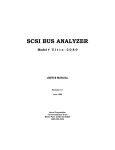
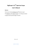
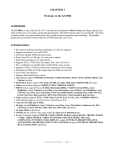
Ultimate2000
User’s Guide
Rev. 2 – November 2000
1
The information in this document is subject to change without notice.
This document contains materials protected by copyright. All rights are reserved. No part of
this manual may be reproduced or transmitted in any form, by any means or for purpose
without express written consent.
Federal Communications Radio Frequency Interference Statement.
Note: This equipment has been tested and found to comply with the limits for a Class B digital
device, Pursuant to part 15 of the FCC Rules. These limits are designed to provide reasonable
protection against harmful interference when the equipment is operated in a residential
installation. This equipment generates, uses and can radiate radio frequency energy and if not
installed and used in accordance with the instruction manual may cause harmful interference
to radio communications. However, there is no guarantee that interference will not occur in a
particular installation. If this equipment does cause harmful interference to radio of television
reception, which can be determined by turning the equipment off or on, the user is encouraged
to try to correct the interference by one or more of the following measures:
l
Reorient or relocate the receiving antenna.
l
Increase the separation between the equipment and receiver.
l
Connect the equipment into an outlet on a circuit different from that to which the receiver
is connected.
l
Consult the dealer or an experienced radio TV technician for help.
Notice :
(1)
The changes or modifications not expressly approved by the party responsible for
compliance could void the user authority to operate the equipment.
(2)
Shielded interface cables and AC power adapter, if any must be used in order to comply
with the emission limits.
CE DECLARATION
This device complies with CE class B.
*EN50081-2
EN55011
*EN50082-1
IEC 801-2
EN61000-3-2
IEC 801-3
EN61000-3-3
IEC 801-4
Printed in Taiwan R.O.C.
All contents are subject to change without notice.
All trademarks are the property of their respective owner.
2
CHAPTER 1
Welcome to Grand Ultimate 2000
1.1 Introduction
Grand Ultimate 2000 is a pocketsize universal VGA to TV converter box. It
supports resolutions up to 1024x768. It is best for choice for PC gaming,
DVD movies, Entertainment, Education and Presentations.
1.2 Product Features
1.
Pure hardware design with simple Plug & Display installation. No
software driver is required and it is compatible with any operation
system
2. Switchable NTSC (United States), NTSC-EIAJ (for Japan), PAL,
PAL-M, PAL-N, PAL-combination-N and SECAM (via RGB OUT)
video systems
800x600@56/60/72/75Hz,
3. Supports
640x480@60/72/75/85Hz,
1024x768@60Hz display modes
4. Supports composite VIDEO, S-VIDEO or RGB (or YUV component)
outputs
5. Supports Screen Position control and ZOOM function
6. Supports SIZE (overscan/underscan) function on 640x480 mode
7. Power conservation by VESA DPMS method, compatible with VGA
Monitor power saving
8. Simultaneous display on VGA monitor and TV
9. True 24 bit A/D converter for the true 16.7 million color conversion
10. Power from Keyboard port
11. Compact form factor: 95mm(L)x55mm(W)x30mm(H)
3
1.3 Application:
1. Entertainment – play VCD and DVD movies on TV. Experience PC
games on TV.
2. Presentations – Ideal for both classrooms and conference rooms.
3. Documentation – Capture PC images on video tape.
4. Training – Easy software training via video tape.
1.4 Mode and Resolution Table
The Grand Ultimate 2000 supports the following VGA display modes:
640
Resolution x
480
Horizontal
Frequency 31.5
(KHz)
Vertical
Frequency( 60
Hz)
640
x
480
640
x
480
640 800
x
x
480 600
800
x
600
800
x
600
800
x
600
1024
x
768
37.9 37.5 43.3 35.2 37.9 48
47.2 48.4
72
75
75
85
56
60
72
60
The Grand Ultimate 2000 supports the following MAC display modes:
Resolution
512x384 640x480 640x480
Horizontal
Frequency
(KHz)
31
35
53.7
Vertical frequency 70
(Hz)
66
85
4
1.5 System Requirements
l
Desktop or Notebook PC compatible with PS/2 or AT keyboard port
and VGA output.
l
TV or VCR that supports NTSC or PAL video standards with
composite video input, S-Video input, RGB video input or SCART
input connector.
1.6 Package Contents
This package contains the following items:
1.
Grand Ultimate 2000 VGA to TV converter
2.
User‘s Manual
3.
S-VIDEO cable
4.
VIDEO cable
5.
Power cable (DIN and MINI-DIN type)
6.
Y cable for IBM PC
7.
RGB to SCART cable (for European version only)
5
CHAPTER 2
Installing the Grand Ultimate 2000
The following section shows the functions of the Grand Ultimate 2000.
Refer to Figure 1 for the outline of Grand Ultimate 2000.
IMPORTANT! Turn your computer OFF before connecting the Grand
Ultimate 2000.
S-VIDEO OUT
VIDEO OUT
3
2
1
DC IN
VGA IN / OUT
Grand UltiMate 2000
SWITCH
4
RGB / YUV OUT
SIZE
Figure.1 Outline of Grand Ultimate 2000
6
ZOOM
2 .1 Connectors of Grand Ultimate 2000
l
VGA IN/OUT (MAC)
:
l
S-VIDEO OUT
:
l
VIDEO OUT
:
l
RGB/YUV OUT
:
l
DC IN
:
VGA Input and output connector.
The Y cable labeled with SCAN
CNVTR connects to this side.
Connects to your TV
supporting the S-VIDEO input.
Connects to the VIDEO IN of
TV.
Connects to your display
device supporting the European
SCART standard with RGB to
SCART cable, or other display
device with RGB input. If the
RGB/YUV OUT is enabled, the
S-VIDEO OUT and VIDEO OUT do
not function simultaneous.
Connects power cable to
keyboard port.
NOTE: Do NOT plug in the keyboard power cable while the computer
in on!
7
2.2 Buttons and Switches of Grand Ultimate 2000
l
TV system switch
Selects the desired video standard output.
NOTE: In the United States, switch 1,2 and three should be ON and
switch four should be OFF.
Television
Standard
NTSC (USA)
NTSC-EIA
PAL-M
PAL-N
PAL-B/D/G/H/I
PAL-Combination N
RGB OUT enable
l
Switch
1
ON
OFF
ON
ON
OFF
OFF
2
ON
ON
OFF
ON
ON
OFF
Switch
3
ON
ON
ON
OFF
OFF
OFF
4
OFF
OFF
OFF
OFF
OFF
OFF
ON
SIZE button
Switch between UNDERSCAN and OVERSCAN. This function is
available on 640x480 mode only. Pressing this button also RESETS
the display to default position.
l
ZOOM button
Toggles between ZOOM and NORMAL display.
l
POSITION button
Press up, down, left and right buttons and the picture will move in the
direction pressed.
8
2.3 Installation
IMPORTANT! Turn your computer OFF before connecting the
Ultimate2000!
Figure A
9
Figure B
NOTE: Do NOT plug in the keyboard power cable while the computer is
on!
B1. Connect the Keyboard Power Adapter (there are two
different types included - use the type that fits into your
keyboard port) to the keyboard port of your computer or the
mouse port of the your laptop. If you do not have a keyboard
port, you will need to purchase an external power supply. See
information regarding EXTERNAL POWER SUPPLY in the
trouble-shooting section of this guide.
NOTE: Laptop users connect the keyboard power adapter to the
keyboard/mouse port.
10
B2. Connect the keyboard into the back of the keyboard power
adapter if you require an external keyboard.
Note: Laptop users may not require this step B2.
B3. Connect the end of the VGA Y-cable labeled PC to the
monitor (or VGA port) on the desktop or laptop.
Figure C
Note: Laptop users may not require step C1.
Figure D
Note: Grand Ultimate 2000 also supports high quality S-VIDEO. If
your TV or VCR supports S-VIDEO IN, we highly recommend you
use it to get the best TV picture.
11
D2. Toggle the display input to correspond with the video input
you are using. For instance, a TV defaults to the antenna or cable
input when it is turned on. You will see either a TV channel or
snow. Using the remote control toggle the input to display the
VIDEO rather than the antenna/cable. Each TV varies slightly,
so you may need to refer to your TV's user's manual for further
assistance.
D3. If your TV does not have a VIDEO input, you may connect
through a VCR's VIDEO IN. Note: Since virtually every VCR is
different, please refer to your VCR User's Manual for exact
instructions for recording an external video source.
To connect a Grand Vision converter to a VCR for recording,
follow these steps:
1. Using either the RCA or the S-video (recommended) cable, connect
from the video out on the Grand Vision converter to the Video IN on
the VCR
2. Using either an RCA or a 75 Ohm coaxial cable connect from the
Video OUT on the VCR to the Video IN on the TV
3. Set the TV/VCR switch on the VCR to "VCR"
4. Set the TV to display the video input signal (Refer to TV's User's
manual for instruction on displaying an external video source)
5. You should be able to see the converted computer display on the TV
6. Insert a blank tape into the VCR and press "RECORD". Stop the
tape after a few moments to test that it is recording.
12
CHAPTER 3
Technical Tips
The following are problems that might arise when using the PC to TV
converter, and possible solutions to them.
Things to Check :
1. VGA-Y cable is backwards: Check the ends of the Y-cable and confirm
that the end labeled "PC" is plugged into your computer, the end labeled
"SCAN CNVRTR" is plugged into the Ultimate2000, and the end labeled
"MONITOR" is either connected to a monitor (on a desktop) or not
connected to anything (laptop).
2. Keyboard power adapter is not plugged in: With the computer OFF,
connect the keyboard power adapter into the keyboard port of the laptop or
desktop. Plugging in the adapter is effectively the same as plugging the
Ultimate2000 into the wall.
3. The input on the display (TV, projector, etc.) is not properly set. If your
display has multiple video inputs, then you have to toggle the inputs to
display the one you need. Typically this is done via the remote.
4. The TV looks fine during boot-up but once the PC enters Windows all I
see is black and white horizontal wavy lines: The display adapter (video
card) is set to a refresh rate not supported by the Ultimate2000.
13
The following procedure is required on most typical systems (Note: your
PC may require a different procedure. Please refer to your PCs
documentation for how to adjust the refresh rate for further information):
Start Menu -> Settings -> Control Panel
Click on the icon "DISPLAY".
Click on SETTINGS tab.
Click on the button "ADVANCED".
Click on ADAPTER tab.
Change the Refresh Rate from Optimal to ADAPTER DEFAULT or 60Hz
and click apply.
If you do not see REFRESH RATE under the ADAPTER tab, click on the
MONITOR tab and be sure that the monitor type is set to:
Desktop users: Super VGA 1024x768 (or desired maximum resolution)
Laptop users: Laptop Display Panel 1024x768 (or equivalent for your
system)
Q&A
Q: How can I enhance the display quality?
A: You can usually decrease the TV contrast and increase brightness
control to get the better picture.
Q: I connect using a NOTEBOOK PC, but no output is displayed on TV.
A: To get a converted image on the TV, you must configure the
laptop computer to display an external VGA signal.
Typically, this is done by toggling the "Fn" key + "F1", "F2", etc.
The actual function key varies with each computer.
Please refer to your computer's User's Manual for specific
instructions for displaying an external VGA signal.
14
The "Fn" + "Fx" toggles between three settings. By default, the LCS
panel is on. The first toggle attempts to power both
the LCD panel and the external signal. Sometimes, laptops do not
have enough power to show both the LCD and the
Grand UltraView, so only a scrambled signal is viewable on the TV.
The third toggle turn off the LCD panel and shows
only the external display (the TV, in this case).
Q: I have an older model of a television. Would I be able to use my
video converter with a television as old as this one?
A: Yes, you may need a special adapter called an RF modulator. This
device converts the composite video signal from your video
converter to an Antenna signal, which can be viewed on your TV
using Channel 3 or 4 or 13. You may also use a VCR in some cases.
Refer to section D3 for more information.
Q: Can I use multiple televisions to view the same image from my
computer?
A: Yes, Grand Ultimate 2000 provides 1 CVBS OUT, 1 S-VHS OUT
and 1 RGB OUT. You may connect one television to the next using a
composite video cable or an S-Video between the “VIDEO IN” and
“VIDEO OUT” ports. We recommend using no more than five or six
televisions.
15
Q: Why can’t I hear audio coming through the Ultimate2000?
A. The Ultimate2000 is designed as a PC to Video converter and
does not do anything with audio. However, transferring audio is
relatively simple. You need a cable that connects between the audio
output of your computer's sound card and the audio input of your TV.
See figure E. Purchase online @ www.Grandtec.com
16
CHAPTER 4
Technical Specifications
VGA IN/OUT connector
Analog RGB and SYNC signal from 15 pin VGA output port of PC or
Notebook PC, and output RGB and SYNC signal to monitor.
Pin
Signal Description
No.
1
Red out, 0.7Vpp ± 0.1Vpp, 75 ohms, to monitor
2
Green out, 0.7Vpp ± 0.1Vpp, 75 ohms, to monitor
3
Blue out, 0.7Vpp ± 0.1Vpp, 75 ohms, to monitor
4
DDC2B bus, SDA signal
5
Green in, 0.7Vpp ± 0.1Vpp, 75 ohms, from PC
6
Ground
7
Ground
8
Ground
9
Red in, 0.7Vpp ± 0.1Vpp, 75 ohms, from PC
10
Blue in, 0.7Vpp ± 0.1Vpp, 75 ohms, from PC
11
HSYNC in, TTL level, from PC
12
VSYNC in, TTL level, from PC
13
HSYNC out, buffered HSYNC in, to monitor
14
VSYNC out, buffered VSYNC in, to monitor
15
DDC2B bus, SCL signal
Note: Case is connected to the ground
17
RGB/YUV OUT
RGB/YUV OUT is 15 pin D type female connector. It can output RGB and
YUV component format signal. If PIN13 short with PIN 14, or turn on
SWITCH 4, it enables RGB format output. If PIN 13 short with PIN 12, it
enables YUV format output. RGB and YUV format cannot be enabled
simultaneously.
Pin No.
Signal Description
1
Blue/V component output, 75 ohms
2
Green/Y component output, 75 ohms
3
Blue/U component output, 75 ohms
4
TV CSYNC, negative sync, 0.6Vpp
5
Ground
6
Ground
7
Ground
8
Ground
9
No connection
10
Ground
11
No connection
12
YUV enable, short with PIN13, enable
YUV output
13
+5V
14
RGB enable, short with PIN 13, enable
RGB output
15
TV CSYNC, negative sync, TTL level
Note: Case is connected to ground
18
S-VIDEO connector
S-VIDEO connector is a 4 pin mini-DIN connector.
VIDEO OUT connector
Composite video out, 1.0Vpp ± 0.2Vpp 75 ohms, negative sync.
Power Consumption : 5V, 500mA
Note: If you prefer to use an external wallmount power supply instead
of the keyboard adapter, you MUST use the following type:
5V, between 400mA and 1000mA, with a center positive connector
or
@ www.Grandtec.com
19
For additional technical support:
On-Line – www.Grandtec.com
Email – [email protected]
Fax – 214-351-3862
Call – 214-956-0447
Telephone support is available M-F, 8:45 – 5:45 CST. Voice-mail is
available during off hours or during busy peak times. Your call will
be returned as soon as possible (usually within 24 hours).
A Return Authorization Number (RA#) is required before returning
any products to the manufacturer for repair. No credits will be given
at any time by the manufacturer. If you desire a credit for the return
of your product, please contact the retailer from whom you originally
purchased the product. Credits are subject to the policies of the
individual retailer.
Warranty
We warrant the Grand Ultimate 2000 shall, for a period of one year from the date
of purchase, be free of any defect in material and workmanship and that it will
perform in accordance with specifications. The sole obligation of this warranty
shall be to either repair or replace at our expense the product, at manufacturer’s
option. The original sales receipt must be supplied for warranty repair.
There are no warranties except as stated. There are no warranties expressed or
implied, including, but not limited to, the implied warranties of merchantability
and of fitness for a particular purpose. In no event shall we be liable for
consequential, incidental, or special damages, including, but not limited to,
damages or loss of data, profits or goodwill.
Products that have been subject to abuse, misuse, vandalism, accident, alteration,
neglect, unauthorized repair or improper installation will not be covered by
warranty.
20