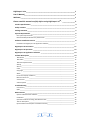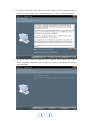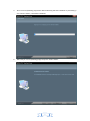
1
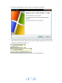
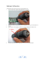
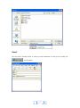
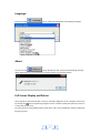
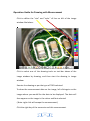
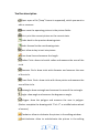
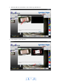
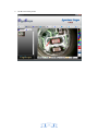
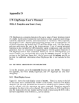
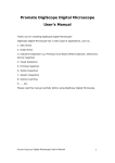
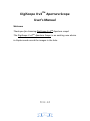
DigiScope II v3TM Aperture Scope User’s Manual Welcome Thank you for choosing DigiScope II v3TM Aperture scope! The DigiScope II v3TM Aperture Scope is an exciting new device to Capture and record the images in the hole. V.3.1.1.2 1 Please read this manual carefully before using DigiScope II v3TM Aperture Scope. 2 DigiScope II v3TM ______________________________________________________ 1 User’s Manual________________________________________________________ 1 Welcome ____________________________________________________________ 1 Please read this manual carefully before using DigiScope II v3TM . ______________ 2 Product Specifications _____________________________________________________ 4 Safety Cautions __________________________________________________________ 4 Package Contents _________________________________________________________ 5 System Requirements _____________________________________________________ 6 PC’s system requirements: ________________________________________________________ 6 Recommended specification for performance: ________________________________________ 6 Software Installation Process _______________________________________________ 6 Installation the DigiScope II v3 Application Software____________________________________ 7 DigiScope II v3 Connection ________________________________________________ 11 DigiScope II v3 Operation _________________________________________________ 12 DigiScope II v3 Application Software ________________________________________ 13 Tool Bar Description ______________________________________________________ 14 Take Picture ___________________________________________________________________ 14 Take Video ____________________________________________________________________ 15 Take time lapsed Pictures ________________________________________________________ 15 Setting _______________________________________________________________________ 16 Save as _______________________________________________________________________ 16 Email ________________________________________________________________________ 17 Language _____________________________________________________________________ 18 About ________________________________________________________________________ 18 Full Screen Display and Return ____________________________________________________ 18 Menu Function List _____________________________________________________________ 19 View Picture __________________________________________________________________ 20 Video Playback ________________________________________________________________ 20 Troubleshooting _________________________________________________________ 22 Common Fix ___________________________________________________________________ 22 Q&A _________________________________________________________________________ 22 Measurement ___________________________________________________________ 24 Open the Measurement Software _________________________________________________ 24 Calibration: ___________________________________________________________________ 26 Operation Guide for Drawing with Measurement _____________________________________ 29 Tool bar description _____________________________________________________________ 30 Dynamic Measurement (Real-Time Measurement) ____________________________________ 32 3 Product Specifications Operation system: Windows XP/Vista and Windows 7 PC interface: USB 2. 0 interface Image Sensor: 1/3.2 inches(5:4) Effective Pixels: 1600(H)x 1200(V),1280(H)x1024(V), 640(H)x480(V), 320(H)x240(V) Frame Rate: 1600(H)x 1200(V)/ 10 ftps,1280(H)x1024(V)/15ftps or 640 x480/30ftps Magnification: 70X -90X (17”LCD display) White Balance: Auto. Exposure: Auto Illumination: 6 whit adjustable LEDs Power Consumption:Max.0.75W Size: 127mm (L) X30mm (R) Safety Cautions Avoid touching the lens with finger to dirty it and protect the product from electrostatic damage. Do not attempt to disassembly any part of this product. Do not attempt to service this product yourself. Opening the covers may expose you to dangerous voltage points or other risks. Storing and operating DigiScope II v3 at Temp: 0°C ~ 45°C, Humidity: 45% ~ 85%, as this will extend Product life and prevent damage to the product. Do not allow this product to have contact with water or other liquids. If water or other liquids enter the product interior, immediately unplug the product from PC. Continued use of the product may result in fire or an electrical shock. Do not use any detergent or volatile solution, which will damage the camera case, painted surfaces and lens. Only use a kens brush on soft cloth to wipe clean. Do not place this product near a heat source or expose direct flame, avoid the lens damaged by high temperature or humidity If the lens is dirty, please use a kens brush on soft cloth to wipe clean. Avoid touching it with your fingers. Exercise care to avoid scratching the lens. Need to read DigiScope II v3 User’s Manual before using and storing it. To avoid electric shock, remove all electricity source before moving PC. 4 Package Contents The DigiScope II v3 Aperture Scope package includes the following: 1. 2. 3. 4. 5. 6. 7. DigiScope II v3 Aperture ScopeDevice CD (Driver) Protective bag Calibration pattern(1.0mm& 2.5mm) x 1pcs Quick Guide manual Disposable specula(tip): black color 3,4 and 5 mm (2 each), transparent 3,4 and 5 mm (2 each) Gift Box 5 System Requirements PC’s system requirements: 1) 2) 3) 4) 5) 6) 7) OS: Windows XP /Vista and windows 7 CPU: Pentium IV 1.0G, Celeron, AMD Athlon or above CD-ROM driver Available USB2.0 port Above 256MB RAM HDD storage space: at least 100MB (for driver and application software installation) Graphic card: 16-bit or above support Direct 9.0C Recommended specification for performance: 1) 2) 3) 4) 5) 6) 7) OS: Windows XP SP2 or Vista SP1,Windows 7 or above CPU: Core2- 2.0GHz or , AMD Athlon 64x2- 2.0GHz above CD-ROM driver Available USB 2.0 port 1.0Gb RAM or above 10GB available hard disk space or above Graphic card: 32-bit above support DirectX 10 or above Software Installation Process The following instructions will guide you to through the process of installing the DigiScope II v3 : Power on PC and place installation CD into CD-ROM drive, do not connect USB Cable from DigiScope II v3 device to PC before software installation. Select software installation, and follow the instructions to complete installation. As driver installation completed, and if system asking for re-start, please re-start the windows OS. Note: The driver needs to be installed only once for each computer. 6 Installation the DigiScope II v3 Application Software 1. Place the installation CD into CD-ROM drive, the installation program should be started automatically. Otherwise, please execute the DigiScope II v3.EXE directly from the CD. 2. Press the key “Install Software”, you will see the following popup .Press “Next” to proceed or “Cancel” to abort installation. 7 3. You will see the End User License Agreement. If you accept the License Agreement, then you can Click the “Next” button which is available to process, or “Cancel” to abort installation. 4. You will be able to install the application. Click “Install” to start to install, click “Cancel” button, it will abort installation. Click on “Back” if you wish to read the End User License Agreement again. 8 5. You will see the following progress bar below indicating that the installation is proceeding. If click “Cancel” button, it will abort installation. 6. Wait until you see the following popup and press “Finish” button. 9 7. Please also install “ffdshow”. And press “Next” to complete the installation. 8. Please plug USB cable to DigiScope II v3 Device to connect with PC. System will automatically search and install the driver. Wait until you see this message that system show “Your new hardware is installed and ready to use”. Now the software installation was completed, you can use DigiScope II v3 . 10 DigiScope II v3 Connection The following procedure will show you how to properly connect DigiScope II v3 with your PC. Connect USB Cable on DigiScope II v3 to PC USB port 11 DigiScope II v3 Operation The following process will show you how to operate DigiScope II v3. i. To have a right image, suggest holding DigiScope II v3 as shown: ii. iii. Put the to-be-observed object(eyeball) near the DigiScope II v3, to put the OTO Capture on the face. Adjust the focus: Use any finger to rotate the “A” roller as shown, till the image is vivid. ”A” Roller iv. The Zoom times will be larger as DigiScope II v3 is closer to the observed object. 12 DigiScope II v3 Application Software Note: Before start DigiScope II v3, please make sure DigiScope II v3 has been connected to PC via USB line Double-Click DigiScope II v3 icon on desktop , the DigiScope II v3 main screen will be shown as below: 13 Tool Bar Description 1. : Two statuses as below: Real-time images show on Preview area under the OTO Capture viewing. Ready to view Pictures or video has been taken. 2. : Take Picture 3. : Take Video 4. : Take time lapsed Pictures 5. : Setting--Picture and Video setting 6. : Save as--A took-picture can be saved as “jpg”, “bmp”, ”png” or ”gif” to your specified disk.. 7. : Email 8. :Language 9. : About 10. :Picture / Video Folder Picture/Video Folder is on the left side of the program, which contains the thumbnails of picture or video captured by the program. The Pictures/video in the folder will not be automatically deleted when closing the program. Thus, it is suggested to save manually the needful picture or video, and then keep this folder clean for file security and program’s performance concern. Take Picture You can take picture by clicking the icon on Tool bar or press this ”Capture button-< C >” on DigiScope II v3 USB Cable Control device. . 14 Take Video The Video can be taken by clicking icon on Tool bar. (Note: This is Video folder as below). Recorder setting: 1. Frame rate: it is the number of frames or images that are projected or displayed per second. The number range is 1~30 2. Timer limit: it is the time of video recording to avoid video file size exceed to the space of disk. The number range is 1~99999 3. Stop: it is available to stop the video recording before the timer setting. Take time lapsed Pictures You can take time lapsed Pictures by click the shown. 15 icon of Tool Bar as below Setting You can select video resolution and set the parameter of video properties by click the button. Save as You can select a picture or video in Picture/Video folder, then click the Icon of Tool Bar, the file can be saved as “jpg”, “bmp”, ”png” or ”gif” picture or video to your specified disk. Show as below. 16 Email You can send a selected picture or video as email attachment to other guy by clicking the Icon of Tool Bar. 17 Language You can click the icon to change the Application panel display language. About You can click the icon of Tool Bar for help. It will pop the following message: About DigiScope II v3: you can check your present version via it as below shown: Full Screen Display and Return These displays of real time preview or picture view/video playback can be enlarged to full screen by clicking the icon on right-top of program screen or double-clicking the left key of mouse in a site of the preview area. To return from full screen display mode, please press “ESC” key of keyboard or double-clicking the left key of mouse. 18 Menu Function List 1. Add in cross line/coordinates/circles/timer on preview area: The mouse stay in the preview area, then click the right key and pop the menu as below. You can click the item you want. You also can capture the picture with cross line/coordinates/circles/timer mark. 2. Select a file in picture/video folder, then clicking the right key of mouse and pop the menu as below. 19 Note: Open-- use “paint” to open it for picture file; use “windows media player” to open it for video file. View Picture You can double-click the selected picture in Picture folder to view it as below shown; : Zoom In :Zoom Out Video Playback You can double-click the selected video in video folder to play back it as below shown 20 : Play/Pause : Stop : Open a avi file : Start : Last 21 Troubleshooting Common Fix A. If DigiScope II v3 device and DigiScope II v3 application were working OK and suddenly stops working properly, Please try the following: 1. 2. 3. 4. Unplug or Power off DigiScope II v3 device from PC Close DigiScope II v3 program After waiting for 1 minute, plug or power on DigiScope II v3 device open DigiScope II v3 program B. For under Recommended PC specification (see 4th page), maybe DigiScope II v3 program does not work properly, Please use the application like AMCAP.exe: direct open it to work,(maybe need these steps: ToolBar->Device: select “DigiScope II v3 device; ToolBar->Option: select “Preview”) C. For Vista first version OS system (Not Vista SP1), maybe there is this issue: there are not any images (black screen) on preview area, please try: Toolbar->setting->default->Ok) D. After PC resume from standby or hibernate, maybe DigiScope II v3 will not work properly, please close it and re-open to try. Q&A Q1. Why the object cannot be found on the display of the DigiScope II v3 Capture? A: a. Please check the all connection of all necessary cable and adapter are right b. Please adjust the illumination of LEDs and make sure those LEDs are light. Q2. Why cannot work when connect to PC? A: a. Check driver and DigiScope II v3 installation are completed. b. The USB cable is connected correctly to DigiScope II v3 Capture and PC USB Port c. Please try to pitch all switches on varied status. Q3. How to install DigiScope II v3 application and driver? A: a. Do not connect USB cable to DigiScope II v3 Capture before driver installation completed. b. Place installation CD into CD-Rom drive, select a right product name of “driver installation”. Q4. How to connect “DigiScope II v3”? A: a. complete driver installation, connect USB cable to DigiScope II v3 Capture, and then Execute “DigiScope II v3” application Program. b. Please check: open DigiScope II v3->setting to see if “Device name” item has an optional 22 device. Q5. How to uninstall driver and DigiScope II v3 software? A: In order to uninstall driver and DigiScope II v3 software, click on the uninstall utility from the Start button ->Control Panel -> Add or Remove Programs. Q6. When connecting to PC, why the real-time display is slow or unsmooth? A: a. Probably your PC’s configuration is not sufficient enough. Please check the Recommended PC specification as mentioned in this User’s Manual. b. Probably your PC’s CPU or memory is overloaded by executing too many applications software. Try to shut down other applications and restart your PC to release the memory. c. Probably your system has being attacked by virus, which may dramatically degrade your system’s performance. Q7. What should we do, if DigiScope II v3 OTO Capture is not working normally? A: a. Please restart the system by disconnecting all the cables from DigiScope II v3 Capture, Wait for about 10 sec., re-connecting the cables to restart. 23 Measurement Open the Measurement Software 1. Select an image in preview browsing folder and right clicking the mouse, then pop-up the context menu as below: Click “ Measure” 24 Click the “Measure” key, then the measurement feature will open as below: Run the Semiautomatic Calibration before using the DigiScope II v3 Aperture Scope to measure your image. 25 Calibration: 1. Click Calibration icon “ ”, and set the magnification to 75x for standard. 2. Put the Digital Viewer II microscope on the Calibration Pattern sheet, you can see the black/white block on the screen. 26 3. Align the Calibration pattern block (black and white) to the white rectangle edge. (To push the “ PgUp” key to enlarge the white rectangle or push the “PgDn” to shrink the white rectangle.) Push “PgUp” key to enlarge the white rectangle 27 Push “PgDn” key to shrink the white rectangle 4. There are 5 blue rectangles in the inside of big white rectangle, and all blue rectangles have one red point. When the 5 red points align on the cross point of black and white block, Please click ”OK” or press ”enter” key to run Calibration. 28 Operation Guide for Drawing with Measurement Click to define the “size” and “color” of line on left of the image window like below: Click to select one of the drawing tools on tool-bar above of the image window by drawing, and then start the drawing in image window. Execute the drawing as per the type of TOOL selected. To show the measurement data on the image, left click again on the image where you would like the data to be displayed. The data will then appear on the image in the colour and font selected. ( Note: right click will escape the measurement.) Click the right key of the mouse to end this measurement. 29 Tool bar description Open: open a file (“bmp” format is supported), which you want to edit or measure. Save: save the operating picture in the picture folder. Print: print the current picture on the current state. Undo: back to the previous drawing state. Redo: forward to the next drawing state. Text: allow to key in text into picture. Line: draw line and measure the length. Radius Circle: draw circle with radius and measure the area of the circle Diameter Circle: draw circle with diameter and measure the area of the circle. Three Point Circle: draw circle with three points and measure the area of the circle. Rectangle: draw rectangle and measure the area of the rectangle. Angle: draw angle and measure the degrees on angle. Polygon: draw the polygon and measure the area in polygon. (Notice: complete the drawing with “Ctrl+ C” or middle button-wheel of mouse.) Clockwise: allow to clockwise the picture in the editing window. Anticlockwise: allow to anticlockwise the picture in the editing 30 window. Sets font: selecting the fonts, size or colors on character. Calibration: semiautomatic calibration by Calibration pattern sheet. Magnify: key the correct magnification in the block according the “A” Roller indication. 31 Dynamic Measurement (Real-Time Measurement) 1. Measure the Line(Length) , Circle(Radius, Area),Rectangle(Width, Height, Area), Angle and Polygon(Area) in “Preview”. 32 Auto fitting (Polygon area) steps 1. Open measurement and click “Auto Polygon” function icon 2. Block the dark area 33 3. Show the dark area, and click the center of dark to get the dark area. 4. Auto polygon to get the dark area 34 5. Get the area on the picture 35