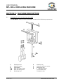
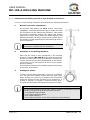
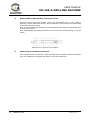
1
USER MANUAL
DRILLING MACHINE
FOR UNDER PRESSURE MAINS
MODEL MP-185-A
Revision No. 1 - January 2004
Publication: MU-41-07E
NOTES !
The modifications carried out against the previous revision of this
publication are indicated with 2 on the right margin.
USER MANUAL
MP-185-A DRILLING MACHINE
CONTENTS:
Page:
SECTION 1:
INTRODUCTION............................................................................
1.1
General.............................................................................
1.2
General information............................................................
1.3
“CE” declaration of conformity..............................................
1.4
Guarantee..........................................................................
SECTION 2:
MACHINE DESCRIPTION................................................................. 7
2.1
Components of the drilling machine....................................... 7
2.2
Machine accessories............................................................ 8
SECTION 3:
MODE OF USE...............................................................................
3.1
Description of the drilling system...........................................
3.1.1 Drilling over CA type branch connections......................
3.1.2 Drilling over CA-C type branch connections..................
SECTION 4:
MAINTENANCE.............................................................................. 13
4.1
General information............................................................. 13
SECTION 5:
TECHNICAL CHARACTERISTICS....................................................... 14
Edition: January 2004
Revision: No. 1
4
4
4
5
6
9
9
9
11
GENERAL CONTENTS -
3
USER MANUAL
MP-185-A DRILLING MACHINE
SECTION 1: INTRODUCTION
1.1
GENERAL
The MP-185-A drilling machine is specially designed to drill on mains, under pressure or
pressureless, on any type of material: gray-iron casting, ductile casting, PVC, PE, PP,
asbestos cement, polyester, clay, steel, etc. It is especially designed to be used on PE pipe
outlet branch connections such as CA and CA-C types.
The machine is easily installed over PE pipe outlet branch connections of diameters 25,
32, 40, 50 and 63 mm, being anchored by means of two anchoring arms. It allows to
carry out a drilling operation up to 46 mm diameter, using standard hole saws with pilot
drill.
It can be operated manually by means of a ratchet wrench, although it is designed to be
used through an electric swivel gear.
For drilling mains under pressure, the maximum allowed pressure is 16 bar (for water
mains).
The machine is robust and easy to use allowing the use of hole saws of different sizes.
The set includes a machine’s bridge, a dome fixing nut, chuckshaft (with pilot drill), two
anchoring arms, one 2.5 mm Allen key, a ½" ratchet wrench, as well as a carrying case
and User Manual.
In addition to the above listed components, a set of separated domes of sizes 25, 32, 40,
50 and 63 mm are available, including hole saws of diameters 17, 22, 27, 38 and 46 mm
respectively.
The technical information provided in this Manual is purely informative, and subject to
change without prior notification. ACUSTER, S.L. shall not be responsible for any claims
derived from misuse of this publication or any errors and/or omissions that could be
detected in it following its publication. This Manual should considered as part of the
machine.
1.2
GENERAL INFORMATION
The development, documentation, production, testing and shipping of the products
described have been performed:
C
C
in compliance with the applicable safety rules, and
in accordance with the Acuster, S.L. quality assurance requirements.
WARNING !
Only qualified personnel are authorized to perform drilling work with the
MP-185-A drilling machine. Qualified personnel must be familiar with all
safety measures, potential hazards and maintenance rules described in this
Manual.
The safe usage of the products described herein requires appropriate
transport, storage, installation and use, careful treatment and compliance
with the pre-established regular maintenance.
4
- INTRODUCTION
Edition: January 2004
Revision: No. 1
USER MANUAL
MP-185-A DRILLING MACHINE
1.3
“CE” DECLARATION OF CONFORMITY
ACUSTER, S.L.
Juan de la Cierva, 1
Polígono Industrial Nº 1
08960 Sant Just Desvern
we declare, under our sole responsibility that the MP-185-A drilling machine
has been manufactured in compliance with the following specifications:
Directive
98/37/CE
Machine safety Directive
Related specification
EN-ISO 12100-1
EN-ISO 12100-2
Model
MP-185-A
Sant Just Desvern, 7th January 2004
Ramon García Solé
Edition: January 2004
Revision: No. 1
INTRODUCTION -
5
USER MANUAL
MP-185-A DRILLING MACHINE
1.4
GUARANTEE
Guarantee declaration:
All MP-185-A drilling machines are manufactured from high quality material and
have been subjected to rigorous tests for resistance and working order as well
as passing all the quality control tests required by the applicable normative (see
"CE" Declaration of conformity).
Regardless of whether an incident might occur during the period of guarantee,
we recommend a careful reading of the following general guarantee conditions.
General conditions of Guarantee:
1.
ACUSTER S.L. guarantees that this product has no manufacturing defect
at the time of its purchase and extends this guarantee for the period of
TWO years.
2.
If the product proves defective during this period, due to the materials or
its assembly, it will be repaired free of charge, including the cost of
materials and labour at Acuster, S.L.'s Technical Service.
3.
The Guarantee is not valid in the following cases:
When the fault in the product is a result of:
!
!
!
!
4.
6
Usual wear and tear due to usage.
Abuse or incorrect use of the unit
Repairs carried out without authority from Acuster, S.L..
Accidents, natural disasters (including lightning, water action etc)
as well as any cause beyond Acuster, S.L.'s control.
In all claims against this guarantee, information relating to the model,
date of purchase, Serial number and any other additional information
must at all times be stated.
- INTRODUCTION
Edition: January 2004
Revision: No. 1
USER MANUAL
MP-185-A DRILLING MACHINE
SECTION 2: MACHINE DESCRIPTION
2.1
COMPONENTS OF THE DRILLING MACHINE
The MP-185-A drilling machine assembly is made of the following components:
1
2
3
3a
3b
4
Feeding screw
Machine bridge
Chuckshaft
Pilot drill of 6.25 mm
Pilot drill fixing stud
Retaining ring
Edition: January 2004
Revision: No. 1
5
6
7
8
Guiding ring
Guiding ring fixing screw
Anchoring arm
½" ratchet wrench
2.5 mm Allen key
Transport case
MACHINE DESCRIPTION -
7
USER MANUAL
MP-185-A DRILLING MACHINE
2.2
MACHINE ACCESSORIES
The MP-185-A drilling machine also features the following accessories:
1
Domes of sizes 25, 32, 40, 50 and 63 mm
1e (*) Hole saws of diameters 17, 22, 27, 38 and 46 mm (included with the domes)
Reducer of diameter 3/8"x1/4" (for 38 and 46 mm hole saws)
(*):
8
In addition to the listed sizes, more sizes are available under request.
Special hole saws for plastic pipes (PE, PP, PVC) are available too.
- MACHINE DESCRIPTION
Edition: January 2004
Revision: No. 1
USER MANUAL
MP-185-A DRILLING MACHINE
SECTION 3: MODE OF OPERATION
3.1
DESCRIPTION OF DRILLING OPERATION
3.1.1 Drilling over CA type branch connections:
To carry out the drilling operation proceed with the following procedure:
1.
Branch connection installation:
The installation of the CA branch connection is performed
placing the saddle and sealing gasket on the pipe. Next,
fasten the clamp between the saddle and mains (the hinge
joints should remain above the saddle), equally tightening
the two fastening bolts to ensure tightness.
For more information, refer to the Fitting Instructions
included with the accessory.
2.
Assembly of the drilling machine:
Install the MP-185-A drilling machine over the branch
connection PE outlet once has been selected the correct
dome and hole saw corresponding to the branch connection
size (do not forget to fit the O-ring or gasket and the
washer).
Fix the drilling machine to the saddle using the anchoring
arms which is provided.
3.
Drilling the mains:
To carry out the drilling operation (under pressure or
pressureless), lower the chuckshaft until the pilot drill
makes contact with the pipe. Now begin drilling the mains
by activating the chuckshaft using the ratchet wrench
included in the equipment, if drilling is manual, or through
a electrical swivel gear. The feed is achieved by making the
feeding screw rotate.
SWIVEL GEAR
If an electrical actuation swivel gear (drilling machine) is optionally used, the
following components shall be necessary to have:
1 (one) Special longer bridge
1 (one) Drilling machine elbow
1 (one) Shaft adapter ½"
1 (one) Drilling machine of low speed (42 mm neck diameter)
Edition: January 2004
Revision: No. 1
MODE OF USE -
9
USER MANUAL
MP-185-A DRILLING MACHINE
4.
Disassembly of the machine and accessories:
Once the mains has been drilled, move the chuckshaft fully up (to make it
possible, tilt the machine’s bridge). On this position, the hole saw will be located
inside the machine’s dome.
If the drilling operation is been carried out underpressure, squeeze the PE outlet
using the CA-EM 50 squeezer (install the squeezer approximately in the middle
of the PE outlet)
Now disassemble the drilling machine and connect the desired fitting in the PE
outlet.
5.
Connecting the branch connection:
Connect the branch connection.
In case of being used the squeeze off system, it is recommended to recover the
PE outlet using the rerounding tool corresponding to the installed size (25, 32, 40,
50 mm).
Retighten the brach connection fasteners.
10 - MODE OF USE
Edition: January 2004
Revision: No. 1
USER MANUAL
MP-185-A DRILLING MACHINE
3.1.2 Underpressure drilling over CA-C type branch connections:
To carry out the drilling operation proceed with the following procedure:
1.
Branch connection installation:
As previous step before the CA-C branch connection
installation, insert the spatula through its saddle slot until
the end travel (oil the spatula with Vaseline). Now install
the branch connection placing the saddle and sealing
gasket on the pipe. Next, fasten the clamp between the
saddle and mains (the hinge joints should remain above
the saddle), equally tightening the two fastening bolts to
ensure tightness.
For more information, refer to the
Instructions included with the accessory.
2.
Fitting
Assembly of the drilling machine:
Once the PE outlet is been positioned in the desired
direction, install the MP-185-A drilling machine over the
branch connection PE outlet once has been selected the
correct dome and hole saw corresponding to the branch
connection size (do not forget to fit the O-ring or gasket
and the washer).
Fix the drilling machine to the saddle using the anchoring
arms which is provided.
3.
Drilling the mains:
To carry out the drilling operation, lower the chuckshaft
until the pilot drill makes contact with the pipe. Now
begin drilling the mains by activating the chuckshaft
using the ratchet wrench included in the equipment, if
drilling is manual, or through a electrical swivel gear.
The feed is achieved by making the feeding screw rotate.
SWIVEL GEAR
If an electrical actuation swivel gear (drilling machine) is optionally used, the
following components shall be necessary to have:
1 (one) Special longer bridge
1 (one) Drilling machine elbow
1 (one) Shaft adapter ½"
1 (one) Drilling machine of low speed (42 mm neck diameter)
Edition: January 2004
Revision: No. 1
MODE OF USE - 11
USER MANUAL
MP-185-A DRILLING MACHINE
4.
Disassembly of the machine and accessories:
Once the mains has been drilled, move the chuckshaft fully up (to make it
possible, tilt the machine’s bridge). On this position, the hole saw will be located
inside the machine’s dome.
Now, move outwards the spatula to its middle position by means of the special tool
to shut off the fluid.
Now disassemble the drilling machine and connect the desired fitting in the PE
outlet.
Special tool to pull out the spatula
5.
Connecting the branch connection:
Connect the branch connection. Using the special tool, totally extract the spatula
from the saddle and retighten the brach connection fasteners.
12 - MODE OF USE
Edition: January 2004
Revision: No. 1
USER MANUAL
MP-185-A DRILLING MACHINE
SECTION 4: MAINTENANCE
4.1
GENERAL INFORMATION
As a general principle, we recommend maintaining the drilling machine (and all
components and accessories) in perfect conditions of cleanliness and lubrication, ready
for use, and stored in their original carrying case.
The preventive maintenance for the equipment is minimal; cleaning and lubricating the
chuckshaft, the spindle threads and machine dome is sufficient. Monitor the cutting
condition of the drill and hole saws before usage. It is recommended they be replaced in
case of fault.
On a regular basis, and especially when the equipment is used over a prolonged period,
we recommend it be sent to the ACUSTER, SL. After-Sales Service Department for a
complete inspection (generally, with time and use, the O-rings and gaskets need to be
changed).
Edition: January 2004
Revision: No. 1
MAINTENANCE - 13
USER MANUAL
MP-185-A DRILLING MACHINE
SECTION 5: TECHNICAL CHARACTERISTICS
Usage
:
Drilling of mains made of steel, gray cast iron,
ductile casting, asbestos cement, clay, polyester,
PVC, PE, PP, etc.
Acuster branch connections
:
CA and CA-C.
Maximum drilling capacity
:
Up to φ. 46 mm
Service pressure
:
16 bar for water mains
Operation
:
Manual by means of ratchet wrench
Optionally by means of an electric actuator
(composed by a longer machine bridge, one propeller
and one shaft adapter of ½").
Total equipment weight
:
7 kg (with carrying case and without domes)
Outer dimensions
:
Length:
Width:
Height:
14 - TECHNICAL CHARACTERISTICS
500 mm
420 mm
200 mm
Edition: January 2004
Revision: No. 1
USER MANUAL
MP-185-A DRILLING MACHINE
NOTES
Edition: January 2004
Revision: No. 1
TECHNICAL CHARACTERISTICS - 15