1
Q2AS(H)CPU(S1)
Mitsubishi Programmable Controller
User’s Manual
(Hardware)
Thank you for purchasing the Mitsubishi programmable controller
MELSEC-QnA series.
Prior to use, please read both this and relevant manual thoroughly to
fully understand the product.
MODEL Q2ASCPU-U(H/W)-E
MODEL
13J857
CODE
IB(NA)-66677-L(1406)MEE
© 1996 MITSUBISHI ELECTRIC CORPORATION
SAFETY PRECAUTIONS
(Read these precautions before using this product.)
Before using this product, please read this manual and the relevant manuals
carefully and pay full attention to safety to handle the product correctly.
In this manual, the safety precautions are classified into two levels:
"
WARNING" and "
CAUTION".
WARNING
Indicates that incorrect handling may cause
hazardous conditions, resulting in death or severe
injury.
CAUTION
Indicates that incorrect handling may cause
hazardous conditions, resulting in minor or moderate
injury or property damage.
Under some circumstances, failure to observe the precautions given under
"
CAUTION" may lead to serious consequences.
Observe the precautions of both levels because they are important for personal
and system safety.
Make sure that the end users read this manual and then keep the manual in a safe
place for future reference.
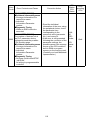
[DESIGN PRECAUTIONS]
WARNING
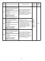
Create a safety circuit outside the programmable controller to ensure the
whole system will operate safely even if an external power failure or a
programmable controller failure occurs.
Otherwise, incorrect output or malfunction may cause an accident.
(1) For an emergency stop circuit, protection circuit and interlock circuit that
is designed for incompatible actions such as forward/reverse rotation or
for damage prevention such as the upper/lower limit setting in
positioning, any of them must be created outside the programmable
controller.
Install the emergency stop switch outsid the controlpanel so that workers
can operate it easily.
A-1
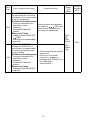
[DESIGN PRECAUTIONS]
WARNING
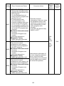
(2) When the programmable controller detects the following error
conditions, it stops the operation and turn off all the outputs.
• The overcurrent protection device or overvoltage protection device of
the power supply module is activated.
• The programmable controller CPU detects an error such as a
watchdog timer error by the self-diagnostics function.
In the case of an error of a part such as an I/O control part that cannot be
detected by the programmable controller CPU, all the outputs may turn
on. In order to make all machines operate safely in such a case, set up a
fail-safe circuit or a specific mechanism outside the programmable
controller.
Refer to "LOADING AND INSTALLATION" in this manual for example
fail safe circuits.
(3) Depending on the failure of the output module’s relay or transistor, the
output status may remain ON or OFF incorrectly. For output signals that
may lead to a serious accident, create an external monitoring circuit.
If load current more than the rating or overcurrent due to a short circuit in the
load has flowed in the output module for a long time, it may cause a fire and
smoke. Provide an external safety device such as a fuse.
Design a circuit so that the external power will be supplied after power-up of
the programmable controller.
Activating the external power supply prior to the programmable controller
may result in an accident due to incorrect output or malfunction.
For the operation status of each station at a communication error in data link,
refer to the respective data link manual.
The communication error may result in an accident due to incorrect output or
malfunction.
A-2
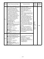
[DESIGN PRECAUTIONS]
WARNING
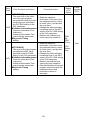
When controlling a running programmable controller (data modification) by
connecting a peripheral device to the CPU module or a PC to a special
function module, create an interlock circuit on sequence programs so that the
whole system functions safely all the time.
Also, before performing any other controls (e.g. program modification,
operating status change (status control)), read the manual carefully and
ensure the safety.
In these controls, especially the one from an external device to a
programmable controller in a remote location, some programmable controller
side problem may not be resolved immediately due to failure of data
communications.
To prevent this, create an interlock circuit on sequence programs and
establish corrective procedures for communication failure between the
external device and the programmable controller CPU.
When setting up the system, do not allow any empty slot on the base unit.
If any slot is left empty, be sure to use a blank cover (A1SG60) or a dummy
module (A1SG62) for it.
When using the extension base unit, A1S52B(S1), A1S55B(S1) or
A1S58B(S1), attach the included dustproof cover to the module in slot 0.
Otherwise, internal parts of the module may be flied in the short circuit test or
when an overcurrent or overvoltage is accidentally applied to external I/O
section.
A-3
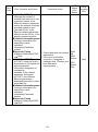
[DESIGN PRECAUTIONS]
CAUTION
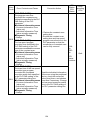
Do not install the control lines or communication cables together with the
main circuit or power lines, or bring them close to each other.
Keep a distance of 100mm (3.94inch) or more between them.
Failure to do so may cause malfunctions due to noise.
If having read register R outside the allowable range with the MOV
instruction, the file register data will be FFFFH. Using this as it is may cause
malfunctions. Pay attention not to use any out-of-range file register when
designing sequence programs. For instruction details, refer to the
programming manual.
When an output module is used to control the lamp load, heater, solenoid
valve, etc., a large current (ten times larger than the normal one) may flow at
the time that the output status changes from OFF to ON. Take some
preventive measures such as replacing the output module with the one of a
suitable current rating.
Time from when the CPU module is powered on or is reset to when it enters
in RUN status dependson the system configuration, parameter settings, and
program size.
Design the program so that the entire system will always operate safely,
regardless of the time.
A-4
[INSTALLATION PRECAUTIONS]
CAUTION
Use the programmable controller under the environment specified in the
user’s manual.
Otherwise, it may cause electric shocks, fires, malfunctions, product
deterioration or damage.
Insert the module fixing projection into the fixing hole in the base unit and
then tighten the module mounting screw within the specified torque.
When no screw is tightened, even if the module is installed correctly, it may
cause malfunctions, a failure or a drop of the module.
Tightening the screw excessively may damage the screw and/or the module,
resulting in a drop of the module, a short circuit or malfunctions.
Connect the extension cable to the connector of the base unit or module.
Check the cable for incomplete connection after connecting it.
Poor electrical contact may cause incorrect inputs and/or outputs.
Insert the memory card and fully press it to the memory card connector.
Check for incomplete connection after installing it.
Poor electrical contact may cause malfunctions.
Be sure to shut off all phases of the external power supply used by the
system before mounting or removing the module. Failure to do so may
damage the module.
Do not directly touch the conductive part or electronic components of the
module.
Doing so may cause malfunctions or a failure of the module.
A-5
[WIRING PRECAUTIONS]
WARNING
Be sure to shut off all phases of the external power supply used by the
system before wiring.
Failure to do so may result in an electric shock or damage of the product.
Before energizing and operating the system after wiring, be sure to attach the
terminal cover supplied with the product.
Failure to do so may cause an electric shock.
CAUTION
Always ground the FG and LG terminals to the protective ground conductor.
Failure to do so may cause an electric shock or malfunctions.
Wire the module correctly after confirming the rated voltage and terminal
layout.
Connecting a power supply of a different voltage rating or incorrect wiring
may cause a fire or failure.
Do not connect multiple power supply modules to one module in parallel.
The power supply modules may be heated, resulting in a fire or failure.
Press, crimp or properly solder the connector for external connection with the
specified tool.
Incomplete connection may cause a short circuit, fire or malfunctions.
Tighten terminal screws within the specified torque range. If the screw is too
loose, it may cause a short circuit, fire or malfunctions.
If too tight, it may damage the screw and/or the module, resulting in a short
circuit or malfunctions.
Carefully prevent foreign matter such as dust or wire chips from entering the
module.
Failure to do so may cause a fire, failure or malfunctions.
Install our programmable controller in a control panel for use.
Wire the main power supply to the power supply module installed in a control
panel through a distribution terminal block.
Furthermore, the wiring and replacement of a power supply module have to
be performed by a maintenance worker who acquainted with shock
protection.
(For the wiring methods, refer to Type Q2AS(H)CPU(S1) User’s Manual.)
A-6
[STARTUP AND MAINTENANCE PRECAUTIONS]
WARNING
Do not touch any terminal during power distribution.
Doing so may cause an electric shock.
Properly connect batteries. Do not charge, disassemble, heat or throw them
into the fire and do not make them short-circuited and soldered. Incorrect
battery handling may cause personal injuries or a fire due to exothermic heat,
burst and/or ignition.
Be sure to shut off all phases of the external power supply used by the
system before cleaning or retightening the terminal screws or module
mounting screws.
Failure to do so may result in an electric shock.
If they are too loose, it may cause a short circuit or malfunctions.
If too tight, it may cause damage to the screws and/or module, resulting in an
accidental drop of the module, short circuit or malfunctions.
A-7
[STARTUP AND MAINTENANCE PRECAUTIONS]
CAUTION
When performing online operations (especially, program modification, forced
output or operating status change) by connecting a peripheral device to the
running CPU module, read the manual carefully and ensure the safety.
Incorrect operation will cause mechanical damage or accidents.
Do not disassemble or modify each of modules.
Doing so may cause failure, malfunctions, personal injuries and/or a fire.
When using a wireless communication device such as a mobile phone, keep
a distance of 25cm (9.84inch) or more from the programmable controller in all
directions.
Failure to do so may cause malfunctions.
Be sure to shut off all phases of the external power supply used by the
system before mounting or removing the module.
Failure to do so may result in failure or malfunctions of the module.
Do not drop or apply any impact to the battery.
Doing so may damage the battery, resulting in electrolyte spillage inside the
battery.
If any impact has been applied, discard the battery and never use it.
Do not install/remove the terminal block more than 50 times after the first use
of the product. (IEC 61131-2 compliant)
Before handling modules, touch a grounded metal object to discharge the
static electricity from the human body.
Failure to do so may cause failure or malfunctions of the module.
A-8
[DISPOSAL PRECAUTIONS]
CAUTION
When disposing of the product, treat it as an industrial waste.
When disposing of batteries, separate them from other wastes according to
the local regulations.
(For details of the battery directive in EU member states, refer to the
Q2AS(H)CPU(S1) User's Manual.)
[TRANSPORTATION PRECAUTIONS]
CAUTION
When transporting lithium batteries, make sure to treat them based on the
transportation regulations. (Refer to Chapter 7 for details of the relevant
models.)
A-9
PRÉCAUTIONS DE SÉCURITÉ
(Lire ces précautions avant toute utilisation du produit.)
Avant d'utiliser ce produit, lire attentivement ce manuel ainsi que les manuels
auxquels il renvoie, et toujours considérer la sécurité comme de la plus haute
importance en manipulant le produit correctement.
Dans ce manuel, les précautions de sécurité sont classées en deux niveaux, à
savoir : "
AVERTISSEMENT" et "
ATTENTION"
AVERTISSEMENT
ATTENTION
Attire l'attention sur le fait qu'une négligence peut
créer une situation de danger avec risque de mort
ou de blessures graves.
Attire l'attention sur le fait qu'une négligence peut
créer une situation de danger avec risque de
blessures légères ou de gravité moyennes ou
risque de dégâts matériels.
Dans certaines circonstances, le non-respect d'une précaution de sécurité
introduite sous le titre "
ATTENTION"peut avoir des conséquences graves.
Les précautions de ces deux niveaux doivent être observées dans leur intégralité
car elles ont trait à la sécurité des personnes et aussi du système.
Veiller à ce que les utilisateurs finaux lisent ce manuel qui doit être conservé
soigneusement à portée de main pour s'y référer autant que de besoin.
[PRÉCAUTIONS DE CONCEPTION]
AVERTISSEMENT
● Prévoir un circuit de sécurité à l'extérieur de l'automate programmable
permettant d'assurer la sécurité de fonctionnement de l'ensemble du système
même en cas de coupure de l'alimentation externe ou de panne de l'automate
programmable.
Faute de quoi, un sortie incorrect ou un dysfonctionnement pourrait causer un
accident.
(1) Comme circuit d'arrêt d'urgence, prévoir un circuit de protection avec
limite de positionnement haute/basse pour la prévention des dommages,
ainsi qu'un circuit d'interdiction des mouvements incompatibles comme la
rotation avant/arrière, ces circuits devant toujours être configurés à
l'extérieur de l'automate programmable.
Le bouton d'arrêt d'urgence doit être installé à l'extérieur du tableau de
commande, facilement accessible par tous les ouvriers.
A-10
[PRÉCAUTIONS DE CONCEPTION]
AVERTISSEMENT
(2) Quand l'automate programmable détecte l'un des états d'erreur ci-après, il
interrompt la marche et il désactive les sorties.
• Le dispositif de protection contre les surtensions ou contre les
surintensités du module d'alimentation a déclenché.
• La CPU d'automate programmable détecte les erreurs du genre
erreur d'horloge de surveillance par sa fonction d'auto-diagnostic.
Dans l'éventualité d'une erreur affectant un organe de commande E/S et
ne pouvant être détectée par la CPU de l'automate programmable, toutes
les sorties pourraient devenir actives. Pour maintenir la sécurité de
fonctionnement de toutes les machines, prévoir une circuit de mise en
sécurité ou un mécanisme adéquat à l'extérieur de l'automate
programmable.
Pour les exemples de circuit de mise en sécurité, voir la "CHARGEMENT
ET INSTALLATION" dans ce manuel.
(3) En cas de défaillance d'un relais ou d'un transistor du module de sortie,
les sorties peuvent rester inopinément à l'état ON ou à l'état OFF. Pour les
signaux de sortie qui pourrait être à l'origine d'un accident grave, créer un
circuit de surveillance externe.
● Si le courant de charge excède la valeur nominale ou si une surintensité
circule longtemps dans le module de sortie suite à une court-circuit, il y a
risque de départ de feu ou de dégagement de fumée. Prévoir un organe de
sécurité externe, par exemple un fusible.
● Prévoir le circuit en sorte que l'alimentation externe soit disponible après la
mise sous tension de l'automate programmable.
Le branchement de l'alimentation externe avant la mise en marche de
l'automate programmable pourrait produire un signal de sortie erroné ou un
dysfonctionnement à l'origine d'un accident.
● Quant à l'état opérationnel de chaque station dans l'éventualité d'une erreur
de communication, voir le manuel de la liaison de données correspondante.
Une erreur de communication peut être à l'origine d'un accident par suite
d'une sortie incorrecte ou d'un dysfonctionnement.
A-11
[PRÉCAUTIONS DE CONCEPTION]
AVERTISSEMENT
● Pour toute intervention sur un automate programmable en marche
(modifications des données) à partir d'un périphérique raccordé au module
CPU ou à partir d'un PC raccordé à un module fonctionnel spécial, créer dans
les programmes séquentiels un circuit de verrouillage assurant en tous temps
la sécurité de fonctionnement de l'ensemble du système.
De plus, avant l'exécution de toute autre instruction (comme une modification
de programme ou un changement d'état opérationnel (commande d'état)), lire
attentivement le manuel pour opérer en toute sécurité.
Pour ces commandes, en particulier celles émanant d'un dispositif externe
vers un automate programmable distant, les problèmes survenant côté
automate programmable ne peuvent pas être immédiatement résolus en cas
d'anomalie dans la communication des données.
Pour éviter cela, prévoir un circuit de verrouillage dans les programmes
séquentiels, et définir le mode opératoire applicable en cas d'erreur de
communication entre le dispositif externe et la CPU d'automate
programmable.
● Au montage du système, il ne doit rester aucune fente à carte vide sur l'unité
de base.
S'il reste une fente à carte vide, il est indispensable de la boucher avec un
couvercle d'obturation (A1SG60) ou d'y insérer un module factice (A1SG62).
Si on utilise une unité de base d'extension A1S52B(S1), A1S55B(S1) ou
A1S58B(S1), recouvrir la fente 0 du module avec le couvercle de propreté
fourni.
Faute de quoi, il peut y avoir claquage des organes internes du module lors
d'un essai de court-circuit ou en cas de surintensité ou de surtension
appliquée accidentellement à la section externe des E/S.
A-12
[PRÉCAUTIONS DE CONCEPTION]
ATTENTION
● Ne pas installer les lignes de commande et les câbles de communication avec
les lignes des circuits principaux ou de l'alimentation, et ne pas les placer à
proximité les uns des autres.
Les installer en maintenant entre eux une distance minimum de 100mm (3,94
pouces).
Faute de quoi, les bruits parasites produiront des dysfonctionnements.
● En cas de lecture du registre R hors de la plage admissible par instruction
MOV, les données de registre fichier sont FFFFH. Son utilisation en l'état
pourrait être à l'origine de dysfonctionnements. À la préparation des
programmes séquentiels, veiller à n'utiliser aucun registre fichier hors de la
zone admissible. Pour des instructions détaillées, se reporter au manuel de
programmation.
● Quand un module de sortie commande un accessoire comme une lampe, un
réchauffeur, une électrovanne etc., un fort courant (jusqu'à dix fois la valeur
normale) circule momentanément lors du changement d'état de OFF à ON. Il
faut en tenir compte en remplaçant si nécessaire le module de sortie module
de sortie par un autre ayant une capacité de courant suffisante.
● Le temps nécessaire à l'entrée en état RUN après la mise sous tension ou le
réarmement du module CPU dépend de la configuration du système, du
paramétrage et de la taille du programme.
● Concevoir le programme de manière que tout le système fonctionne en
sécurité, indépendamment de ce délai.
A-13
[PRÉCAUTIONS D'INSTALLATION]
ATTENTION
● Utiliser l'automate programmable dans l'environnement prescrit par le manuel
de l'utilisateur.
Faute de quoi, il y a risque de chocs électriques, de départ de feu, de
dysfonctionnements ou d'endommagement du produit.
● Introduire l'ergot de fixation du module dans le trou correspondant sur l'unité
de base et serrer les vis de fixation du module au couple prescrit.
Si on ne serre pas la vis, même si le module a bien pris sa place, il peut y
avoir dysfonctionnement, panne ou même chute du module.
Un serrage excessif pourrait endommager la vis et/ou le module et il y aurait
aussi risque de chute du module, de court-circuit ou de dysfonctionnements.
● Raccorder le câble d'extension sur le connecteur de l'unité de base ou du
module. Vérifier qu'il n'y a pas de connexion imparfaite après raccordement
du câble.
Un mauvais contact électrique peu produire des entrées et/sorties erratiques.
● Insérer la carte-mémoire en la poussant à fond dans le connecteur pour
carte-mémoire. Après installation, vérifier qu'il n'y a pas de connexions
incomplètes.
Un mauvais contact électrique peut être à l'origine de dysfonctionnements.
● Avant la mise en place ou le retrait du module, vérifier que l'alimentation
externe utilisée par le système a bien été coupée sur toutes les phases. Faute
de quoi, il y aurait risque d'endommagement du module.
● Éviter tout contact direct avec les parties conductrices ou composants
électroniques du module.
Cela pourrait être à l'origine de dysfonctionnements ou d'une panne du
module.
[PRÉCAUTIONS DE CABLAGE]
AVERTISSEMENT
● Avant le câblage, vérifier que l'alimentation externe utilisée par le système a
bien été coupée sur toutes les phases.
Faute de quoi, il y aurait risque de choc électrique ou d'endommagement du
produit.
● En fin de câblage, avant de mettre sous tension le système pour la mise en
marche, mettre en place le couvre-bornes fourni avec le produit.
Faute de quoi, il y aurait risque de choc électrique.
A-14
[PRÉCAUTIONS DE CABLAGE]
ATTENTION
● Toujours mettre à la masse les bornes FG et LG sur le conducteur de
protection de terre.
Faute de quoi, il y aurait risque de choc électrique ou de dysfonctionnement.
● Câbler le module correctement après vérification de la tension nominale et de
l'affectation des bornes.
Le raccordement d'une alimentation de tension nominale différente ou toute
erreur de câblage peuvent être à l'origine d'un départ de feu ou d'une panne.
● Ne pas raccorder plusieurs modules d'alimentation en parallèle sur un même
module.
La surchauffe des modules d'alimentation pourrait entraîner un départ de feu
ou être à l'origine d'une panne.
● Presser, sertir ou braser correctement le connecteur pour connexion externe
en utilisant l'outil prescrit.
Une connexion imparfaite peut être à l'origine d'un court-circuit, d'un départ de
feu ou de dysfonctionnements.
● Serrer les vis de bornes dans les limites du couple de serrage prescrit. Une
vis desserrée peut être à l'origine d'un court-circuit, d'un départ de feu ou de
dysfonctionnements.
Un serrage excessif peut endommager les vis et/ou le module et provoquer
un court-circuit ou des dysfonctionnements.
● Prendre grand soin de ne laisser pénétrer dans le module aucun corps
étranger, poussière, débris de fil ou autres.
Faute de quoi, il y a risque de départ de feu, de panne ou de
dysfonctionnement.
● Installer l'automate programmable dans un tableau de commande.
Pour le câblage de l'alimentation principale vers le module d'alimentation
installé en tableau de commande, utiliser un bloc de distribution.
En outre, le câblage et le remplacement d'un module d'alimentation ne
doivent être effectués que un personnel de maintenance formé à la protection
contre les chocs électriques.
(Quand aux méthodes de câblage, voir le manuel de l'utilisateur Type
Q2AS(H)CPU(S1).)
A-15
[PRÉCAUTIONS DE MISE EN SERVICE ET DE MAINTENANCE]
AVERTISSEMENT
● Ne toucher à aucune des bornes quand l'équipement est sous tension.
Il aurait risque de choc électrique.
● Raccorder les batteries correctement. Ne pas recharger, démonter, chauffer
ou jeter au feu, et ne pas court-circuiter ou souder les bornes. Un mauvais
traitement des batteries pourrait être à l'origine de blessures ou produire un
départ de feu s'il y a dégagement de chaleur, explosion et/ou inflammation.
● Avant le nettoyage ou le resserrage des vis de borne ou des vis de fixation du
module, vérifier que l'alimentation externe utilisée par le système a bien été
coupée sur toutes les phases.
Faute de quoi, il y aurait risque de choc électrique.
Desserrées, elles peuvent causer un court-circuits ou des
dysfonctionnements.
Un serrage excessif peut endommager les vis et/ou le module et, en cas de
chute, provoquer un court-circuit ou des dysfonctionnements.
A-16
[PRÉCAUTIONS DE MISE EN SERVICE ET DE MAINTENANCE]
ATTENTION
● Pour toute intervention en ligne (en particulier, pour une modification de
programme, une sortie forcée ou un changement d'état opérationnel) par
raccordement d'un périphérique au module CPU en marche, lire
attentivement le manuel pour opérer en toute sécurité. Une manœuvre
incorrecte peut être à l'origine de dégâts matériels ou d'accidents.
● Ne pas démonter ou tenter de modifier les modules.
Cela pourrait être à l'origine de pannes, dysfonctionnements, blessures et/ou
d'un départ de feu.
● Pour utiliser un appareil de communication sans fil, comme un téléphone
portable, le tenir éloigné de l'automate programmable d'une distance d'au
moins 25cm (9,84 pouces), dans tous les sens.
Faute de quoi, il y aurait risque de dysfonctionnements.
● Avant la mise en place ou le retrait du module, vérifier que l'alimentation
externe utilisée par le système a bien été coupée sur toutes les phases.
Faute de quoi, il peut en résulter des pannes ou dyfonctionnements de
modules.
● Ne pas faire tomber la pile et ne pas l'exposer à des chocs.
Cela pourrait endommager la batterie et entraîner une fuite de l'électrolyte
que contient la batterie.
Une pile qui a subi un choc ne doit jamais être utilisée mais mise au rebut.
● Après la mise en service du produit, le nombre maximum admissible
d'opérations de pose/retrait de la plaque à bornes est de 50 (selon IEC 611312).
● Avant de manipuler les modules, toucher un objet métallique raccordé à la
terre pour éliminer la charge d'électricité statique qu'accumule le corps
humain.
Faute de quoi, il y aurait risque de panne ou de dysfonctionnement du
module.
A-17
[PRÉCAUTIONS DE MISE AU REBUT]
ATTENTION
● Pour le mettre au rebut, ce produit doit être traité comme un déchet industriel.
Les piles ou batteries doivent être mises au rebut séparément des autres
déchets et conformément à la réglementation locale.
(Pour le détail de la Directive sur les piles et batteries dans les états membres
de l'UE, voir le manuel de l'utilisateur Q2AS(H)CPU(S1).)
[PRÉCAUTIONS DE TRANSPORT]
ATTENTION
● Pour le transport des batteries et piles au lithium, toujours respecter la
réglementation afférente au transport de ce genre de marchandises. (Pour le
détail des modèles concernés, voir Chapitre 7.)
A-18
A-19
A-20
A-21
A-22
A-23
A-24
A-25
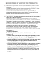
CONDITIONS OF USE FOR THE PRODUCT
(1) Mitsubishi programmable controller ("the PRODUCT") shall be used in
conditions;
i) where any problem, fault or failure occurring in the PRODUCT, if any,
shall not lead to any major or serious accident; and
ii) where the backup and fail-safe function are systematically or
automatically provided outside of the PRODUCT for the case of any
problem, fault or failure occurring in the PRODUCT.
(2) The PRODUCT has been designed and manufactured for the purpose of
being used in general industries.
MITSUBISHI SHALL HAVE NO RESPONSIBILITY OR LIABILITY
(INCLUDING, BUT NOT LIMITED TO ANY AND ALL RESPONSIBILITY
OR LIABILITY BASED ON CONTRACT, WARRANTY, TORT, PRODUCT
LIABILITY) FOR ANY INJURY OR DEATH TO PERSONS OR LOSS OR
DAMAGE TO PROPERTY CAUSED BY the PRODUCT THAT ARE
OPERATED OR USED IN APPLICATION NOT INTENDED OR
EXCLUDED BY INSTRUCTIONS, PRECAUTIONS, OR WARNING
CONTAINED IN MITSUBISHI'S USER, INSTRUCTION AND/OR
SAFETY MANUALS, TECHNICAL BULLETINS AND GUIDELINES FOR
the PRODUCT.
("Prohibited Application")
Prohibited Applications include, but not limited to, the use of the
PRODUCT in;
• Nuclear Power Plants and any other power plants operated by Power
companies, and/or any other cases in which the public could be
affected if any problem or fault occurs in the PRODUCT.
• Railway companies or Public service purposes, and/or any other cases
in which establishment of a special quality assurance system is
required by the Purchaser or End User.
• Aircraft or Aerospace, Medical applications, Train equipment, transport
equipment such as Elevator and Escalator, Incineration and Fuel
devices, Vehicles, Manned transportation, Equipment for Recreation
and Amusement, and Safety devices, handling of Nuclear or
Hazardous Materials or Chemicals, Mining and Drilling, and/or other
applications where there is a significant risk of injury to the public or
property.
A-26
Notwithstanding the above, restrictions Mitsubishi may in its sole
discretion, authorize use of the PRODUCT in one or more of the
Prohibited Applications, provided that the usage of the PRODUCT is
limited only for the specific applications agreed to by Mitsubishi and
provided further that no special quality assurance or fail-safe, redundant
or other safety features which exceed the general specifications of the
PRODUCTs are required. For details, please contact the Mitsubishi
representative in your region.
A-27
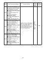
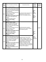
REVISIONS
*The manual number is given on the bottom right of the front cover.
Print Date
Jan., 1996
Sep., 1998
*Manual Number
IB(NA) 66677-A
IB(NA) 66677-B
Dec., 2002
IB(NA) 66677-C
Dec., 2003
IB(NA) 66677-D
Jul., 2005
IB(NA) 66677-E
Oct., 2006
IB(NA) 66677-F
May, 2007
IB(NA) 66677-G
Oct., 2008
IB(NA) 66677-H
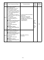
Revision
First edition
Correction
SAFETY PRECAUTIONS, Section 4.5.2
Addition
Specifications, Performance specifications,
EMC standards,
Low-Voltage instruction
Deletion
I/O module specifications and connections
Equivalent to Japanese version E
Correction
SAFETY PRECAUTIONS, 1.1, Chapter 3,
Section 4.2, 4.3.1, 4.3.2, 4.5.2, Chapter 5,
Chapter 6, Section 6.2
Addition of model
A1SY42P
Addition
Chapter 7, Section 7.1, 7.2
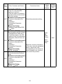
Correction
SAFETY PRECAUTIONS, Section 5.2.1, 5.2.2,
5.3.1, 5.3.2, 6.2
Correction
SAFETY PRECAUTIONS, Section 1.1, Chapter 3,
Section 3.1, 3.1.1, 3.1.2, 3.1.3, 3.2, 3.2.4, 3.2.7,
4.1.1, 4.2, 4.3.1, 4.3.2, 4.3.3, 4.3.4, 4.4, 6.2, 6.3
Section change
Section 6.1, 6.2 are changed to Section 6.2, 6.3,
respectively.
Addition of model
A1SY40P, A1SY41P
Addition
Section 6.5, 6.6, 6.7, 6.8, 6.9, 6.10
Correction
SAFETY PRECAUTIONS, Section 1.1, 3.1.3, 3.2.4,
3.2.6, 4.1.1, 4.1.3, 4.3.2, 4.3.3, 4.3.4, 5.2.1, 5.2.2,
Chapter 6
Partial Correction
Section 3.1.1, 3.1.3, 3.1.4, 3.2.7, 4.3.3, 4.3.4, 5.2.1,
6.3
Partial Correction
SAFETY PRECAUTIONS, Section 1.1, 3.1, 3.1.1,
3.1.2, 3.1.3, 3.2, 3.2.1, 3.2.2, 3.2.3, 3.2.4, 3.2.5,
3.2.6, 3.2.7, 4.1.3, 4.2, 4.3.3, 4.3.4, 4.5.2, 5.1.1,
5.2.1, Chapter 6
A-28
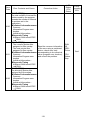
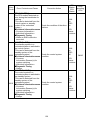
*The manual number is given on the bottom right of the front cover.
Print Date
Jul., 2009
*Manual Number
IB(NA) 66677-I
Jan., 2011
IB(NA) 66677-J
Dec., 2011
IB(NA) 66677-K
Jun., 2014
IB(NA) 66677-L
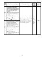
Revision
Partial Correction
Section 1.1, Chapter 3, Section 6.3
Partial Correction
SAFETY PRECAUTIONS, CONDITIONS OF USE
FOR THE PRODUCT, Relavant Manuals,
Section 1.1, 2.1, Chapter 3, Section 3.1, 3.1.1,
3.1.3, 3.1.4, 3.1.6, 4.2, 4.3.1, 4.3.3, 4.4, 5.1.1, 5.1.2,
5.2.1, 5.2.2, 5.3.1, 5.3.2
Addition
Section 3.1.8, 3.1.9
Partial Correction
Section 1.1, 3.1.1, 6.3.5
Addition
SAFETY PRECAUTIONS(Chinese)
Partial Correction
Section 1.1, 3.1.3, 4.1.1, 4.3.1, 4.3.4, 5.1.2, 5.2.2, 5.3.2, 6.3
Addition
SAFETY PRECAUTIONS(French)
Japanese Manual Version IB(NA)68653-N
This manual confers no industrial property rights or any rights of any other kind, nor dose it
confer any patent licenses. Mitsubishi Electric Corporation cannot be held responsible for any
problems involving industrial property rights which may occur as a result of using the contents
noted in this manual.
© 1996 Mitsubishi Electric Corporation
A-29
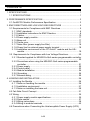
CONTENTS
1. SPECIFICATIONS .......................................................................................... 1
1.1 SPECIFICATIONS ................................................................................... 1
2. PERFORMANCE SPECIFICATION ............................................................... 3
2.1 QnASCPU Module Performance Specification ........................................ 3
3. EMC DIRECTIVES AND LOW VOLTAGE DIRECTIVES .............................. 5
3.1 Requirements for Compliance with EMC Directives................................. 5
3.1.1 EMC standards ................................................................................. 6
3.1.2 Installation instructions for EMC Directive......................................... 8
3.1.3 Cables ............................................................................................. 10
3.1.4 Power supply module...................................................................... 17
3.1.5 Base unit ......................................................................................... 17
3.1.6 Ferrite core...................................................................................... 17
3.1.7 Noise filter (power supply line filter) ................................................ 18
3.1.8 Power line for external power supply terminal ................................ 18
3.1.9 Installation environment of the CC-Link/LT module and the AS-i
module ............................................................................................ 19
3.2 Requirements for Compliance with Low Voltage Directives .................. 20
3.2.1 Standard applied for MELSECs-QnA series programmable controller
........................................................................................................ 20
3.2.2 Precautions when using the MELSEC-QnA series programmable
controller ......................................................................................... 21
3.2.3 Power supply .................................................................................. 22
3.2.4 Control panel................................................................................... 23
3.2.5 Module installation .......................................................................... 24
3.2.6 Grounding ....................................................................................... 24
3.2.7 External wiring ................................................................................ 25
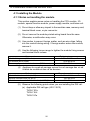
4. LOADING AND INSTALLATION .................................................................. 26
4.1 Installing the Module .............................................................................. 26
4.1.1 Notes on handling the module ........................................................ 26
4.1.2 Installation environment .................................................................. 27
4.1.3 Notes on installing the base unit ..................................................... 28
4.2 Fail-Safe Circuit Concept ....................................................................... 31
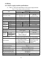
4.3 Wiring ..................................................................................................... 35
4.3.1 Power supply module specifications ............................................... 35
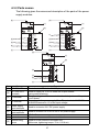
4.3.2 Parts names .................................................................................... 37
4.3.3 Wiring instructions........................................................................... 38
4.3.4 Wiring to module terminals ............................................................. 42
4.4 Precautions when Connecting the Uninterruptible Power Supply (UPS)
............................................................................................................... 44
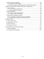
A-30
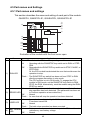
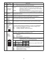
4.5 Part names and Settings ........................................................................ 45
4.5.1 Part names and settings ................................................................. 45
4.5.2 Relation between switch operation and the LED indication ............ 48
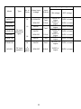
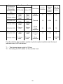
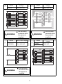
5. SPECIFICATION AND CONNECTION OF I/O MODULES .......................... 53
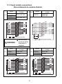
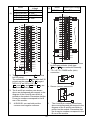
5.1 Input modules ......................................................................................... 53
5.1.1 Input module specifications ............................................................. 53
5.1.2 Input module connections ............................................................... 57
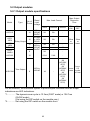
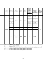
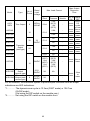
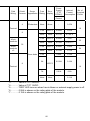
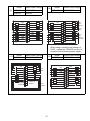
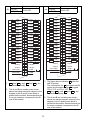
5.2 Output modules ...................................................................................... 63
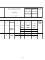
5.2.1 Output module specifications .......................................................... 63
5.2.2 Output module connections ............................................................ 69
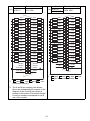
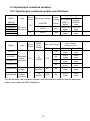
5.3 Input/output combined modules ............................................................. 79
5.3.1 Input/output combined module specifications ................................. 79
5.3.2 Input/output composite module connections ................................... 81
6. ERROR CODE.............................................................................................. 84
6.1 Error Code Type ..................................................................................... 85
6.2 Reading Error Code................................................................................ 86
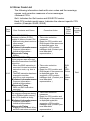
6.3 Error Code List ....................................................................................... 87
6.4 Canceling of Errors ............................................................................... 139
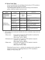
7. TRANSPORTATION PRECAUTIONS ....................................................... 140
7.1 Relevant Models................................................................................... 140
7.2 Transportation Guidelines .................................................................... 140
A-31
This manual explains safety precautions, I/O module wiring, and error codes
regarding the Q2ASCPU, Q2ASCPU-S1, Q2ASHCPU, and Q2ASHCPU-S1
(hereinafter, these are all referred to as Q2ASCPU).
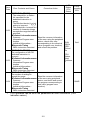
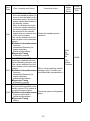
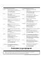
About this manual
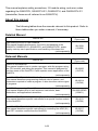
The following tables show the manuals relevant to this product. Refer to
these tables when you order a manual, if necessary.
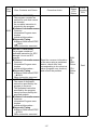
Detailed Manual
Manual title
Manual number
(Type code)
type Q2AS(H)CPU(S1) User's Manual
This manual explains performance, functions, and handling of the
Q2ASCPU, Q2ASCPU-S1, Q2ASHCPU, and Q2ASHCPU-S1, power
supply, memory card, specifications, and handling of the base unit.
(sold separately)
SH-3599
(13J858)
Relavant Manuals
Manual number
(Type code)
Manual title
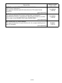
QnACPU-GUIDEBOOK
This manual explains how to create a program, write the program using
the CPU module, and debug the program. This manual is designed for
first-time users of the QnACPU. It also explains some applications of the
QnACPU.
(sold separately)
QnACPU PROGRAMMING MANUAL (Fundamentals)
This manual describes programming methods, device names, and
parameters required to create a program. It also describes various types
of programs.
(sold separately)
QnACPU Programming Manual(Common Instructions)
This manual explains how to use sequence instructions, basic
instructions, and application instructions.
(sold separately)
QnACPU PROGRAMMING MANUAL (Special Function)
This manual describes specific instructions for a special function module
for the QnACPU.
(sold separately)
QnACPU PROGRAMMING MANUAL (AD57 Instructions)
This manual describes specific instructions for controlling the AD57(S1)
type CRT controller module from the QnACPU.
(sold separately)
A-32
IB-66606
(13JF10)
IB-66614
(13JF46)
SH-080810ENG
(13JW11)
SH-4013
(13JF56)
IB-66617
(13JF49)
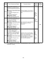
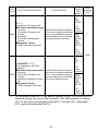
Manual number
(Type code)
Manual title
QCPU(Q mode)/QnACPU PROGRAMMING MANUAL
(PID Control Instructions)
This manual describes specific instructions for PID control for the
QnACPU.
(sold separately)
QCPU(Q mode)/QnACPU PROGRAMMING MANUAL (SFC)
This manual describes the system configuration, performance
specifications functions, programming, debugging procedures, and the
error codes of the SW0SRX-SAP3 and SW0NX-SAP3.
(sold separately)
Ans Module type I/O User's Manual
This manual describes the specifications for the compact building block
type I/O modules.
(sold separately)
A-33
SH-080040
(13JF59)
SH-080041
(13JF60)
IB-66541
(13JF81)
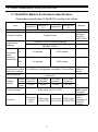
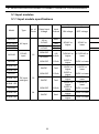
1. SPECIFICATIONS
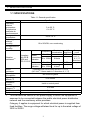
1.1 SPECIFICATIONS
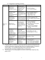
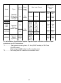
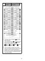
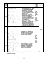
Table 1.1 General specification
Item
Operating
ambient
temperature
Température
ambiante de
fonctionnement
Storage ambient
temperature
Operating
ambient
humidity
Storage ambient
humidity
Specifications
0 to 55 °C
0 à 55 °C
−20 to 75 °C
10 to 90%RH, non-condensing
Frequency
Vibration
resistance*4
Shock
resistance
Operating
atmosphere
Operating
altitude *3
Installation
location
Overvoltage
category *1
Pollution level *2
Equipment class
*1
Constant
Half
acceleration amplitude
3.5mm
5 to 9Hz
Compliant
Under
with JIS B
intermittent
9 to 150Hz
9.8m/s2
3502 and
vibration
IEC 61131-2
Under
5 to 9Hz
1.75mm
continuous
9 to 150Hz
4.9m/s2
vibration
Compliant with JIS B 3502 and IEC 61131-2
(147 m/s2, 3 times each in 3 directions X, Y, Z)
Sweep
count
10 times
each in
X, Y, Z
directions
-
No corrosive gases
0 to 2000m
Inside a control panel
II or less
2 or less
Class I
This indicates the section of the power supply to which the equipment is
assumed to be connected between the public electrical power distribution
network and the machinery within premises.
Category II applies to equipment for which electrical power is supplied from
fixed facilities. The surge voltage withstand level for up to the rated voltage of
300V is 2500V.
1
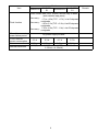
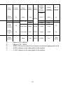
*2
*3
*4
This index indicates the degree to which conductive material is generated in
terms of the environment in which the equipment is used. Pollution level 2 is
when only non-conductive pollution occurs. A temporary conductivity caused
by condensing must be expected occasionally.
Do not use or store the programmable controller under pressure higher than
the atmospheric pressure of altitude 0m. Doing so may cause malfunction.
When using the programmable controller under pressure, please consult
your local Mitsubishi Electric representative.
When an A series extension base unit (A52B, A55B, A58B, A62B, A65B,
A68B) is used in the system, the following specifications apply.
Under
intermittent
vibration
Under
continuous
vibration
Frequency
10 to 57Hz
Acceleration
-
57 to 150Hz
9.8m/s2
-
10 to 57Hz
-
0.035mm
57 to 150Hz
4.9m/s2
-
2
Amplitude
0.075mm
Sweep count
10 times each in
X, Y, Z directions
-
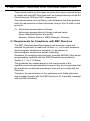
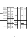
2. PERFORMANCE SPECIFICATION
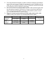
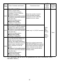
2.1 QnASCPU Module Performance Specification
Performance specification of Q2ASCPU module is as follows:
Item
Model
Q2ASCPUQ2ASHCPUQ2ASHCPU
S1
S1
Repetitive operation of stored program
Q2ASCPU
Control method
I/O control method
I/O enabled by
specifying
direct I/O
(DX, DY)
Sequence control dedicated language
Relay symbol language, logic symbolic language,
MELSAP3 (SFC)
Programming
language
Processing
speed
(sequence
instructions)
Refresh mode
Remark
LD
0.2 µs/step
0.075 µs/step
MOV
0.6 µs/step
0.225 µs/step
Constant scan
(Function that makes
scan time constant)
Set parameter
5 to 2000 ms (configurable in multiple of 5 ms module) values to
specify
Capacity of loading memory cards (2036 kbyte
Memory capacity
maximum)
Number 28 k steps
60 k steps
28 k steps
60 k steps
of steps maximum
maximum
maximum
maximum
Program
capacity
Number
28 files
60 files
28 files
60 files
of files
Number of
I/O device points
8192 points (X/Y0 to 1FFF)
usable points
in program
Number of
512 points
points
1024 points
512 points 1024 points
I/O points
(X/Y0 to
accessible to
(X/Y0 to 3FF) (X/Y0 to 1FF) (X/Y0 to 3FF)
1FF)
actual I/O
modules
3
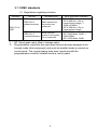
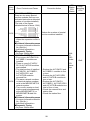
Item
Clock function
Allowable momentary
power failure period
5 VDC Internal
current consumption
Mass
External dimension
Model
Q2ASCPUQ2ASHCPUQ2ASHCPU
S1
S1
Year, month, date, hour, minute, second, day of week
(auto-detects leap years)
Accuracy :
-1.7 to +4.9s (TYP. +1.7s) / d at 0 depress
centigrade
Accuracy :
-1.0 to +5.2s (TYP. +2.2s) / d at 25 depress
centigrade
-7.3 to +2.5s (TYP. -1.9s) / d at 55 depress
Accuracy :
centigrade
Q2ASCPU
By power supply module
0.3 A
0.3 A
0.7 A
0.7 A
0.5 kg
0.5 kg
0.5 kg
0.5 kg
130(H) mm × 54.5(W) mm × 110(D) mm (5.12inch ×
2.15inch × 4.33inch)
4
Remark
3. EMC DIRECTIVES AND LOW VOLTAGE DIRECTIVES
The products sold in the European countries have been required by law
to comply with the EMC Directives and Low Voltage Directives of the EU
Directives since 1996 and 1997, respectively.
The manufacturers must confirm by self-declaration that their products
meet the requirements of these directives, and put the CE mark on the
products.
(1) Authorized representative in Europe
Authorized representative in Europe is shown below.
Name: Mitsubishi Electric Europe BV
Address: Gothaer Strase 8, 40880 Ratingen, Germany
3.1 Requirements for Compliance with EMC Directives
The EMC Directives specifies emission and immunity criteria and
requires the products to meet both of them, i.e., not to emit excessive
electromagnetic interference (emission): to be immune to
electromagnetic interference outside (immunity).
Guidelines for complying the machinery including MELSEC-QnA series
programmable controller with the EMC Directives are provided in
Section 3.1.1 to 3.1.9 below.
The guidelines are created based on the requirements of the
regulations and relevant standards, however, they do not guarantee that
the machinery constructed according to them will not comply with the
Directives.
Therefore, the manufacturer of the machinery must finally determine
how to make it comply with the EMC Directives: if it is actually compliant
with the EMC Directives.
5
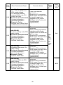
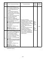
3.1.1 EMC standards
(1) Regulations regarding emission
Standard
EN61131-2:
2007
Test item
CISPR16-2-3
Radiated emission
*2
Test description
Radio waves from
the product are
measured.
CISPR16-2-1,
Noise from the
CISPR16-1-2
product to the power
Conducted emission
line is measured.
*2
*1
*2
Value specified in standard
• 30M-230MHz
QP: 40dBµV/m (10m in
measurement range) *1
• 230M-1000MHz
QP: 47dBµV/m (10m in
measurement range)
• 150k-500kHz
QP: 79dB, Mean: 66dB *1
• 500k-30MHz
QP: 73dB, Mean: 60dB
QP: Quasi-peak value, Mean: Average value
Programmable controllers are open-type devices (devices designed to be
housed inside other equipment) and must be installed inside a conductive
control panel. The corresponding tests were conducted with the
programmable controller installed inside a control panel.
6
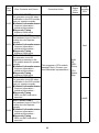
(2) Regulations regarding immunity
Standard
Test item
EN61000-4-2
Electrostatic
discharge immunity
*1
EN61000-4-3
Radiated, radiofrequency,
electromagnetic field
immunity *1
EN61000-4-4
Electrical fast
transient/burst
immunity *1
EN61131-2:
2007
EN61000-4-5
Surge immunity *1
EN61000-4-6
Immunity to
conducted
disturbances,
induced by radiofrequency fields *1
EN61000-4-8
Power-frequency
magnetic field
immunity *1
EN61000-4-11
Voltage dips and
interruption
immunity *1
*1
*2
Test description
Immunity test in
which electrostatic
is applied to the
cabinet of the
equipment.
Value specified in standard
• 8kV Air discharge
• 4kV Contact discharge
Immunity test in
80% AM modulation@1kHz
which electric fields • 80M-1000MHz: 10V/m
are irradiated to the • 1.4G-2.0GHz: 3V/m
product.
• 2.0G-2.7GHz: 1V/m
Immunity test in
which burst noise is
applied to the power
line and signal line.
Immunity test in
which lightning
surge is applied to
the power line and
signal line.
• AC/DC main power, I/O power,
AC I/O (unshielded): 2kV
• DC I/O, analog, communication:
1kV
• AC power line, AC I/O power,
AC I/O (unshielded)
: 2kV CM, 1kV DM
• DC power line, DC I/O power
: 0.5kV CM, DM
• DC I/O, AC I/O (shielded),
analog*2, communication
: 1kV CM
Immunity test in
which high
0.15M-80MHz, 80% AM
frequency noise is
modulation@1kHz, 10Vrms
applied to the power
line and signal line.
Immunity test in
which the product is
50Hz/60Hz, 30A/m
installed in inductive
magnetic field.
Immunity test in
• Apply at 0%, 0.5 cycles and
which power supply
zero-cross point
voltage is
• 0%, 250/300 cycles (50/60Hz)
momentarily
• 40%, 10/12 cycles (50/60Hz)
interrupted.
• 70%, 25/30 cycles (50/60Hz)
Programmable controllers are open-type devices (devices designed to be
housed inside other equipment) and must be installed inside a conductive
control panel. The corresponding tests were conducted with the
programmable controller installed inside a control panel.
The accuracy of an analog-digital converter module may temporary vary
within ±10%.
7
3.1.2 Installation instructions for EMC Directive
The programmable controller is open equipment and must be installed
within a control cabinet for use.* This not only ensures safety but also
ensues effective shielding of programmable controller-generated
electromagnetic noise.
* Also, each network remote station needs to be installed inside the
control panel.
However, the waterproof type remote station can be installed
outside the control panel.
(1) Control cabinet
(a) Use a conductive control cabinet.
(b) When attaching the control cabinet's top plate or base plate,
mask painting and weld so that good surface contact can be
made between the cabinet and plate.
(c) To ensure good electrical contact with the control cabinet, mask
the paint on the installation bolts of the inner plate in the control
cabinet so that contact between surfaces can be ensured over
the widest possible area.
(d) Earth the control cabinet with a thick wire so that a low
impedance connection to ground can be ensured even at high
frequencies.
(e) Holes made in the control cabinet must be 10 cm (3.94 in.)
diameter or less. If the holes are 10 cm (3.94 in.) or larger,
radio frequency noise may be emitted.
(f)
Lock the control panel so that only those who are trained and
have acquiredenough knowledge of electric facilities can open
the control panel.
8
(2) Connection of power and earth wires
Earthing and power supply wires for the programmable controller
system must be connected as described below.
(a) Provide an earthing point near the power supply module. Earth
the power supply's LG and FG terminals (LG: Line Ground, FG:
Frame Ground) with the thickest and shortest wire possible.
(The wire length must be 30 cm (11.81 in.) or shorter.) The LG
and FG terminals function is to pass the noise generated in the
programmable controller system to the ground, so an
impedance that is as low as possible must be ensured. In
addition, make sure to wire the ground cable short as the wires
are used to relieve the noise, the wire itself carries large noise
content and thus short wiring means that the wire is prevented
from acting as an antenna.
(b) The earth wire led from the earthing point must be twisted with
the power supply wires. By twisting with the earthing wire,
noise flowing from the power supply wires can be relieved to
the earthing. However, if a filter is installed on the power
supply wires, the wires and the earthing wire may not need to
be twisted.
9
3.1.3 Cables
The cables extracted from the control panel contain a high frequency
noise component. On the outside of the control panel, therefore, they
serve as antennas to emit noise. To prevent noise emission, use
shielded cables for the cables which are connected to the I/O modules
and intelligent function modules and may be extracted to the outside of
the control panel.
The use of a shielded cable also increases noise resistance.
The signal lines (including common line) of the programmable
controller, which are connected to I/O modules, intelligent function
modules and/or extension cables, have noise durability in the condition
of grounding their shields by using the shielded cables. If a shielded
cable is not used or not grounded correctly, the noise resistance will not
meet the specified requirements.
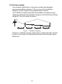
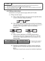
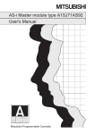
(1) Earthing of shielded of cables
(a) Earth the shield of the shielded cable as near the unit as
possible taking care so that the earthed cables are not induced
electromagnetically by the cable to be earthed.
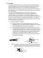
(b) Take appropriate measures so that the shield section of the
shielded cable from which the outer cover was partly removed
for exposure is earthed to the control panel on an increased
contact surface. A clamp may also be used as shown in the
figure below. In this case, however, apply a cover to the
painted inner wall surface of the control panel which comes in
contact with the clamp.
Screw
Shield section
Clamp fitting
Paint mask
Shielded cable
Note) The method of earthing by soldering a wire onto the shield section of
the shielded cable as shown below is not recommended. The high
frequency impedance will increase and the shield will be ineffective.
Shielded cable
Wire
Crimp terminal
10
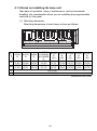
(2) MELSECNET (II) and MELSECNET/10 modules
(a) Use a double-shielded coaxial cable for the MELSECNET
module which uses coaxial cables such as A1SJ71AR21,
A1SJ71LR21 and A1SJ71BR11. Noise in the range of 30 MHz
or higher in radiation noise can be suppressed by the use of
double-shielded coaxial cables (manufactured by MITSUBISHI
CABLE INDUSTRIES, LTD: 5C-2V-CCY). Earth the outer
shield to the ground
Earth this section
For the shield grounding, refer to item (1).
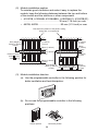
(b) Make sure to attach a ferrite core to the double-shielded
coaxial cable connected to the MELSECNET module. In
addition, position the ferrite core on each cable near the outlet
of the control panel. The ferrite core manufactured by TDK
Corporation, ZCAT3035-1330, is recommended.
(3) Ethernet module
Precautions to be followed when AUI cables and coaxial cables are
used are described below.
(a) Always earth the AUI cables*1 connected to the 10BASE5
connectors. Because the AUI cable is of the shielded type,
strip part of the outer cover and earth the exposed shield
section to the ground on the widest contact surface as shown
below.
AUI cable
Shield
11
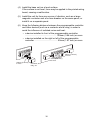
(b) Use shielded twisted pair cables as the twisted pair cables*1
connected to the 10BASE-T connectors. For the shielded
twisted pair cables, strip part of the outer cover and earth the
exposed shield section to the ground on the widest contact
surface as shown below.
Shielded twisted pair cables
Shield
Refer to (1) for the earthing of the shield
*1 Make sure to install a ferrite core for the cable.
The ferrite core manufactured by TDK Corporation,
ZCAT2032-0930, is recommended.
(c) Always use double-shielded coaxial cables as the coaxial
cables*2 connected to the 10BASE2 connectors. Earth the
double-shielded coaxial cable by connecting its outer shield to
the ground.
Shield
Earth here
Refer to (1) for the earthing of the shield
*2 Make sure to install a ferrite core for the cable.
The ferrite core manufactured by TDK Corporation,
ZCAT3035-1330, is recommended.
Ethernet is the registered trademark of XEROX, Co.,LTD
(4) I/O and other communication cables
For the I/O signal lines (including common line) and other
communication cables (RS-232, RS-422, etc), if extracted to the
outside of the control panel, also ensure to earth the shield section
of these lines and cables in the same manner as in item (1) above.
12
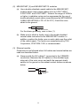
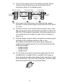
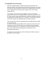
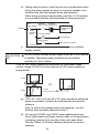
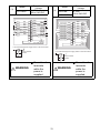
(5) Positioning Modules
Precautions to be followed when the machinery conforming to the
EMC Directive is configured using the A1SD75P-S3 are
described below.
A1SD75
module
CPU module
Power supply
module
(a) When wiring with a 2 m (6.56 ft.) or less cable
• Ground the shield section of the external wiring cable with
the cable clamp.
(Ground the shield at the closest location to the A1SD75
external wiring connector.)
• Wire the external wiring cable to the drive unit and external
device with the shortest practicable length of cable.
• Install the drive unit in the same panel.
External wiring connector
Cable clamp
External wiring cable (within 2 m (6.56 ft.))
Drive unit
A1SD75
module
CPU module
Power supply
module
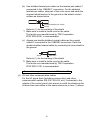
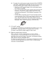
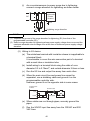
(b) When wiring with cable that exceeds 2 m (6.56 ft.), but is 10 m
(32.81 ft.) or less
• Ground the shield section of the external wiring cable with
the cable clamp.
(Ground the shield at the closest location to the A1SD75
external wiring connector.)
• Install a ferrite core.
• Wire the external wiring cable to the drive unit and external
device with the shortest practicable length of cable.
External wiring connector
Ferrite core
Cable clamp
External wiring cable (2 m to 10 m (6.56 ft. to 32.81 ft.))
Drive unit
13
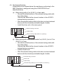
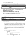
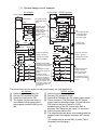
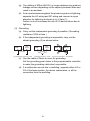
(c) Ferrite core and cable clamp types and required quantities
• Cable clamp
Type : AD75CK (manufactured by Mitsubishi Electric
Corporation)
• Ferrite core
Type : ZCAT3035-1330 (manufactured by TDK
Corporation)
Contact: TDK Corporation
• Required quantity
Cable length
Prepared part
Within 2 m (6.56 ft.)
AD75CK
AD75CK
2 m (6.56 ft.)
to 10m (32.81 ft.) ZCAT3035-1330
Required Qty
1 axis 2 axes 3 axes
1
1
1
1
1
1
1
2
3
A1S
D75
Inside control panel
AD75CK
20 to 30cm
(7.87 to 11.81 inch)
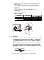
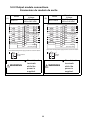
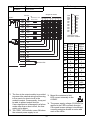
(6) CC-Link Module
(a) Be sure to ground the cable shield that is connected to the CCLink module close to the exit of control panel or to any of the
CC-Link stations within 30 cm (11.81 in.) from the module or
stations.
The CC-Link dedicated cable is a shielded cable. As shown in
the illustration below, remove a portion of the outer covering
and ground as large a surface area of the exposed shield part
as possible.
CC-Link dedicated cable
Shield
(b) Always use the specified CC-Link dedicated cable.
14
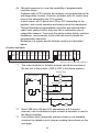
(c) The CC-Link module, the CC-Link stations and the FG line
inside the control panel should be connected at the FG
terminal as shown in the diagram below.
Master module
Remote module
(Blue)
DA
(White)
DB
Terminal
(Yellow)
DG
resistor
SLD
FG
CC-Link
dedicated
cable
DA
DB
DG
SLD
FG
Local module
CC-Link
dedicated
cable
DA
DB
DG
SLD
FG
Terminal
resistor
(d) Each power line connecting to the external power supply
terminal or module power supply terminal must be 30m (98.43
ft) or less.
(e) Install a noise filter to the external power supply. Use a noise
filter with an attenuation characteristic equivalent to that of the
MA1206 (TDK-Lambda Corporation). Note that a noise filter is
not required when the module is used in Zone A defined in
EN61131-2.
(f)
Keep the length of signal cables connected to the analog input
terminals of the following modules to 30m or less.
Wire cables connected to the external power supply and
module power supply terminal in the control panel where the
module is installed.
• AJ65BT-64RD3
• AJ65BT-64RD4
• AJ65BT-68TD
(g) For the cable connected to the power supply terminal of the
AJ65SBT-RPS, AJ65SBT-RPG or AJ65BT-68TD, attach a
ferrite core with an attenuation characteristic equivalent to that
of the ZCAT3035- 1330 from TDK Corporation. Twist the cable
around the ferrite core by one as shown below.
15
(h) To supply the module power supply terminal of the AJ65BTB216R/16DR, AJ65SBTB2N-8A/8R/8S/16A/16R/16S with power
using the AC/DC power supply, follow as shown below.
• Install the AC/DC power supply in the control panel where
the module is installed.
• Use a CE-marked AC/DC power supply and ground the FG
terminals. (The AC/DC power supply used for the tests
conducted by Mitsubishi: TDK-Lambda Corporation: DLP120-24-1)
• For the cable connected to the AC input terminal and DC
output terminals of the AC/DC power supply, attach a ferrite
core. Twist the cable around the ferrite core by one as
shown below. (Ferrite core used for the tests conducted by
Mitsubishi: NEC TOKIN Corporation: ESD-SR-250)
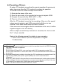
(7) CC-Link/LT module
To supply the CL2DA2-B and CL2AD4-B with 24VDC power using
the CL1PAD1, keep the length of the power cable from the
CL1PAD1 to the 24VDC power supply to 30m or less.
(8) Measures against static electricity
When using an insulation displacement connector without
connector cover, a connected cable for the connector is thin in
applicable wire size and coating. Therefore, note that the module
may cause an electric discharge failure.
As measures against the failure, using pressure-displacement type
connector whose applicable wire size is thick or soldering type
connector is recommended.
16
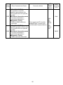
3.1.4 Power supply module
The precautions required for each power supply module are described
below. Always observe the items noted as precautions.
Mosdel
A1S61PN, A1S62PN
A1S63P *1
A1SJHCPU(S8)
*1
*2
Precautions
Make sure to short the LG and FG terminals with a cable of 6 to
7cm and ground the cable.
Use the 24VDC panel power equipment conforming to the EU
Directive.
Make sure to short and ground the LG and FG terminals.*2
Filter attachment to the power cable is not required for the A1S63P product
with the version (F) and later. However, use the 24VDC panel power
equipment that conforms to the CE.
Make sure to attach two ferrite cores to the power line.
Attach them as close to the power supply module as possible.
Use a ferrite core whose damping characteristic is equivalent to that of the
RFC-H13 produced by KITAGAWA INDUSTREIS CO., LTD.
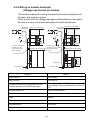
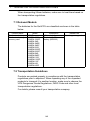
3.1.5 Base unit
The following table shows models of base units that are compatible with
EMC instructions.
Type
Main base unit
Extension base unit
Model name
A1S38HBEU
A1S3B, A1S38HB
A1S5B(S1), A1S6B(S1)
Applicability
Applicable
Not applicable
Applicable
3.1.6 Ferrite core
Use of ferrite cores is effective in reducing the conduction noise in the
band of about 10 MHz and radiated noise in 30 to 100 MHz band.
It is recommended to attach ferrite cores when the shield of the shielded
cable coming out of the control panel does not work effectively, or when
emission of the conduction noise from the power line has to be
suppressed.
We tested using ferrite cores from TDK Corporation, ZCAT3035-1330
and ZCAT2032-0930, and RFC-H13 from KITAGAWA INDUSTREIS
CO., LTD.
Make sure to attach a ferrite core to a cable at the position closest to the
outlet of control panel as possible. If attached at an improper position,
the ferrite core will not work effectively.
• Ferrite core
Type
: ZCAT3035-1330, ZCAT2032-0930
Contact : TDK Corporation
Type
: RFC-H13
Contact : KITAGAWA INDUSTREIS CO., LTD
17
3.1.7 Noise filter (power supply line filter)
TA noise filter is a component which has an effect on conducted noise.
With the exception of some models, it is not required to fit the noise filter
to the power supply line, but fitting it can further suppress noise. (The
noise filter has the effect of reducing conducted noise of 10 M Hz or
less.) Use any of the following noise filters (double π type filters) or
equivalent.
Model name
Manufacturer
Rated current
Rated voltage
FN343-3/01
SCHAFFNER
3A
FN660-6/06
SCHAFFNER
6A
250 V
ZHC2203-11
TDK
3A
The precautions required when installing a noise filter are described
below.
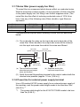
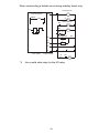
(1) Do not bundle the wires on the input side and output side of the
noise filter. When bundled, the output side noise will be induced
into the input side wires from which the noise was filtered.
Input side
Input side
(power supply side) (power supply side)
Induction
Filter
Filter
Output side
(device side)
Output side
(device side)
(a) The noise will be included
when the input and output
wires are bundled.
(b) Separate and lay the
input and output wires.
(2) Earth the noise filter earthing terminal to the control cabinet with the
shortest wire possible (approx. 10 cm (3.94 in.)).
3.1.8 Power line for external power supply terminal
Use a CE-marked AC/DC power supply for an external power supply of
the modules, and the power cable length needs to be less than 30m
(98.43 ft.).*1
*1 The power cable length for the A1SJ71E71N-B5 needs to be less
than 3m (9.84 ft.).
18
Install noise filters to external supply power terminals of the I/O module
and the modules below.
Use noise filters whose damping characteristic is equivalent to that of
the MA1206 produced by TDK Lambda Corporation.
• Analog-digital converter module
• Digital-analog converter module
• Analog I/O module
• Temperature input module
• Temperature control module
• Pulse input module
• High-speed counter module
• Positioning module
3.1.9 Installation environment of the CC-Link/LT module and
the AS-i module
(1) CC-Link/LT module
Use the module under the environment of Zone A*1.
For the categories of the following products, refer to the manual
came with each product.
• CL1Y4-R1B1
• CL1Y4-R1B2
• CL1XY4-DR1B2
• CL1XY8-DR1B2
• CL1PSU-2A
(2) AS-i module
Use the module under the environment of Zone A*1.
*1 Zone defines categories according to industrial environment,
specified in the EMC and Low Voltage Directives, EN61131-2.
Zone C: Factory mains (isolated from public mains by
dedicated transformer)
Zone B: Dedicated power distribution, secondary surge
protection (rated voltage: 300V or less)
Zone A: Local power distribution, protected from dedicated
power distribution by AC/DC converter and insulation
transformer (rated voltage: 120V or less)
19
3.2 Requirements for Compliance with Low Voltage Directives
The Low Voltage Directives apply to the electrical equipment operating
from 50 to 1000VAC or 75 to 1500VDC; the manufacturer must ensure
the adequate safety of the equipment.
Guidelines for installation and wiring of MELSEC-QnA series
programmable controller are provided in Section 3.2.1 to 3.2.7 for the
purpose of compliance with the EMC Directives.
The guidelines are created based on the requirements of the
regulations and relevant standards, however, they do not guarantee that
the machinery constructed according to them will comply with the
Directives.
Therefore, the manufacturer of the machinery must finally determine
how to make it comply with the EMC Directives: if it is actually compliant
with the EMC Directives.
3.2.1 Standard applied for MELSECs-QnA series
programmable controller
The standard applied for MELSEC-QnA series programmable controller
series is EN61010-1 safety of devices used in measurement rooms,
control rooms, or laboratories.
For the modules which operate with the rated voltage of 50 VAC/75
VDCorabove,wehavedevelopedn
ew models that conform to the above standard.
For the modules which operate with the rated voltage under 50 VAC/75
VDC, the conventional models can be used, because they are out of the
low voltage directive application range.
20
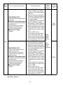
3.2.2 Precautions when using the MELSEC-QnA series
programmable controller
Module selection
(1) Power module
For a power module with rated input voltage of 100/200 VAC, select
a model in which the internal part between the first order and
second order is intensively insulated, because it generates
hazardous voltage (voltage of 42.4 V or more at the peak) area.
For a power module with 24 VDC rated input, a conventional model
can be used.
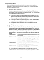
(2) I/O module
For I/O module with rated input voltage of 100/200 VAC, select a
model in which the internal area between the first order and second
order is intensively insulated, because it has hazardous voltage
area.
For I/O module with 24 VDC rated input, a conventional model can
be used.
(3) CPU module, memory cassette, base unit
Conventional models can be used for these modules, because they
only have a 5 VDC circuit inside.
(4) Special function module
Conventional models can be used for the special modules including
analog module, network module, and positioning module, because
the rated voltage is 24 VDC or smaller.
(5) Display device
Use the CE-marked product.
21
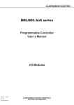
3.2.3 Power supply
The insulation specification of the power module was designed
assuming installation category II. Be sure to use the installation
category II power supply to the programmable controller.
The installation category indicates the durability level against surge
voltage generated by a thunderbolt. Category I has the lowest durability;
category IV has the highest durability.
Category IV
Category III
Category II
Category I
Figure 1. : Installation Category
Category II indicates a power supply whose voltage has been reduced
by two or more levels of isolating transformers from the public power
distribution.
22
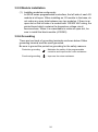
3.2.4 Control panel
Because the programmable controller is an open device (a device
designed to be stored within another module), be sure to use it after
storing in the control panel.
(1) Electrical shock prevention
In order to prevent persons who are not familiar with the electric
facility such as the operators from electric shocks, the control panel
must have the following functions:
(a) The control panel must be equipped with a lock so that only
the personnel who has studied about the electric facility and
have enough knowledge can open it.
(b) The control panel must have a structure which automatically
stops the power supply when the box is opened.
(c) For electric shock protection, use IP20 or greater control
panel.
(2) Dustproof and waterproof features
The control panel also has the dustproof and waterproof functions.
Insufficient dustproof and waterproof features lower the insulation
withstand voltage, resulting in insulation destruction. The insulation
in our programmable controller is designed to cope with the
pollution level 2, so use in an environment with pollution level 2 or
below.
Pollution level 1:
Pollution level 2:
Pollution level 3:
Pollution level 4:
An environment where the air is dry and conductive dust
does not exist.
An environment where conductive dust does not usually
exist, but occasional temporary conductivity occurs due
to the accumulated dust. Generally, this is the level for
inside the control panel equivalent to IP54 in a control
room or on the floor of a typical factory.
An environment where conductive dust exits and
conductivity may be generated due to the accumulated
dust.
An environment for a typical factory floor.
Continuous conductivity may occur due to rain, snow,
etc. An outdoor environment.
As shown above, the programmable controller can realize the
pollution level 2 when stored in a control panel equivalent to IP54.
23
3.2.5 Module installation
(1) Installing modules contiguously
In Q2AS series programmable controllers, the left side of each I/O
module is left open. When installing an I/O module to the base, do
not make any open slots between any two modules. If there is an
open slot on the left side of a module with 100/200 VAC rating, the
printed board which contains the hazardous voltage circuit
becomes bare. When it is unavoidable to make an open slot, be
sure to install the blank module (A1SG60).
3.2.6 Grounding
There are two kinds of grounding terminals as shown below. Either
grounding terminal must be used grounded.
Be sure to ground the protective grounding for the safety reasons.
Protective grounding
: Maintains the safety of the programmable
controller and improves the noise resistance.
Functional grounding
: Improves the noise resistance.
24
3.2.7 External wiring
(1) Module power supply and external power supply
For the remote module which requires 24VDC as module power
supply, the 5/12/24/48VDC I/O module, and the intelligent function
module (special function module) which requires the external
power supply, use the 5/12/24/48VDC circuit which is doubly
insulated from the hazardous voltage circuit or use the power
supply whose insulation is reinforced.
(2) External devices
When a device with a hazardous voltage circuit is externally
connected to the programmable controller, use a model whose
circuit section of the interface to the programmable controller is
intensively insulated from the hazardous voltage circuit.
(3) Intensive insulation
Intensive insulation refers to the insulation with the dielectric
withstand voltage shown in Table 1.
Table 1: Intensive Insulation Withstand Voltage
(Installation Category II, source: IEC664)
Rated voltage of hazardous voltage area
150 VAC or below
300 VAC or below
Surge withstand voltage (1.2/50 µs)
2500 V
4000 V
25
4. LOADING AND INSTALLATION
4.1 Installing the Module
4.1.1 Notes on handling the module
This section explains some notes on handling the CPU module, I/O
module, special function module, power supply module, and base unit.
(1) Do not drop or allow any impact to the modules case, memory card,
terminal block cover, or pin connector.
(2) Do not remove the module printed wiring board from the case.
Otherwise, a malfunction may occur.
(3) Use caution to prevent foreign matter, such as wire chips, falling
into the module during wiring. If foreign matter enters the module,
remove it.
(4) Use the fallowing torque range to tighten the module fixing screws
and terminal block screws:
Screw portion
Module fixing screw (M4 screw)
I/O module (M3.5 screw)
Power supply module terminal screws (M3.5 screw)
(4)
Tightening torque range
78 to 118 Ncm
59 to 88 Ncm
59 to 78 Ncm
Appliquer le couple de serrage suivant lors du serrage des vis de
fixation de module et des vis de borniers.
Partie vissante
Vis de fixation du module (vis M4)
Module d'entrée/sortie (vis M3,5)
Vis de borne du module d'alimentation (vis M3,5)
Plage de couple de serrage
78 à 118 Ncm
59 à 88 Ncm
59 à 78 Ncm
(5) Observe the following points when you are installing the DIN rail:
(a) Applicable DIN rail type (JIS C 2812)
TH35-7.5Fe
TH35-7.5Al
TH35-15Fe
26
(b) DIN rail installation screw interval
When you are using the TH35-7.5Fe or TH35-7.5Al DIN rail,
tighten the DIN rail installation screw with a pitch of 200 mm
(7.87 inch) or less to maintain the strength.
DIN rail installation screw
DIN rail
35 mm
(1.38 inch)
P
P
P
P=200 mm (7.87 inch) or less
(6) When installing the base unit to DIN rail in an environment with
large vibration, use a vibration-proofing bracket (A1S-PLT-D).
Mounting the vibration-proofing bracket (A1S-PLT-D) enhances the
resistance to vibration.
Depending on the environment to set up the base unit, it is also
recommended to fix the base unit to the control panel directly.
4.1.2 Installation environment
Avoid the following environment when you install the CPU system:
(1) A location in which the ambient temperature falls outside the range
of 0 to 55 degrees Celsius.
(2) A location in which the ambient humidity falls outside the range of
10 to 90%RH.
(3) A location in which condensation may occur due to drastic changes
in temperature.
(4) A location in which corrosive gas or flammable gas exists.
(5) A location in which the system is easily exposed to conductive
powder, such as dust and iron filings, oil mist, salt, or organic
solvent.
(6) A location exposed to direct sunlight.
(7) A location in which strong electrical or magnetic fields are
generated.
(8) A location in which the module is exposed to direct vibration or
impact.
27
4.1.3 Notes on installing the base unit
Take ease of operation, ease of maintenance, and environmental
durability into consideration when you are installing the programmable
controller on the panel.
Hs
H
(1) Mounting dimension
Mounting dimensions of each base unit are as follows:
Ws
W
W
Ws
H
Hs
A1S32
B
A1S33
B
220
(8.66)
200
(7.87)
255
(10.04)
235
(9.25)
A1S38B
A1S52
A1S38HB
B
A1S38HBE
(S1)
U
325
430
155
(12.80)
(16.93)
(6.10)
305
410
135
(12.01)
(16.14)
(5.31)
130 (5.12)
110 (4.33)
A1S35
B
A1S55
B
(S1)
A1S58
B
(S1)
A1S65
B
(S1)
A1S68
B
(S1)
260
(10.24)
240
(9.45)
365
(14.37)
345
(13.58)
315
(12.40)
295
(11.61)
420
(16.54)
400
(15.75)
Dimensions: mm (inch)
28
(2) Module installation position
To maintain good ventilation and make it easy to replace the
module, keep the following distances between the top and bottom
of the module and the structure or other components.
• A1S3B, A1S38HB, A1S38HBEU, A1S5B(S1), A1S6B(S1)
................................................................ 30 mm (1.18 inch) or over
• A5B, A6B......................................... 80 mm (3.15 inch) or over
This shows the position of the panel's ceiling,
wiring duct, or components.
Main base
Duct (Height of
50mm (1.97inch)
or less)
Extension base unit
(A1S5 B (S1),
A1S6 B(S1))
30mm
(1.18inch)
or more
Main base
30mm
(1.18inch)
or more
30mm (1.18inch)
or more
30mm
(1.18inch)
or more
30mm (1.18inch)
or more
80mm
(3.15inch)
or more
30mm (1.18inch)
or more
Duct (Height of
Extension base unit
50mm (1.97inch)
(A5 B (S1), A6 B(S1))
or less)
80mm
(3.15inch)
or more
(3) Module installation direction
(a) Use the programmable controller in the following position for
better ventilation and heat dissipation:
(b) Do not use the programmable controller in the following
positions:
Vertical position
Horizontal position
29
(4) Install the base unit on a level surface.
If the surface is not level, force may be applied to the printed wiring
board, causing a malfunction.
(5) Install the unit far from any source of vibration, such as a large
magnetic contactor and a no-fuse breaker on the same panel, or
install it on a separate panel.
(6) Keep the following distance between the programmable controller
and other devices (such as a contactor and a relay) in order to
avoid the influence of radiated noise and heat:
• a device installed in front of the programmable controller
.............................................................. 100mm (3.94 inch) or more
• a device installed on the right or left of the programmable
controller .............................................. 50mm (1.97 inch) or more
50mm (1.97inch)
or more
50mm (1.97inch)
or more
100mm (3.94inch)
or more
Contactor, and
relay, etc.
30
4.2 Fail-Safe Circuit Concept
When the programmable controller is powered ON and then OFF,
improper outputs may be generated temporarily depending on the delay
time and start-up time differences between the programmable controller
power supply and the external power supply for the control target
(especially, DC).
For example, if the external power supply for the control target is
powered ON and then the programmable controller is powered ON, the
DC output module may generate incorrect outputs temporarily upon the
programmable controller power-ON. Therefore, it is required to build the
circuit that energizes the programmable controller by priority.
The external power failure or programmable controller failure may lead
to the system error.
In order to eliminate the possibility of the system error and ensure failsafe operation, build the following circuit outside the programmable
controller: emergency circuit, protection circuit and interlock circuit, as
they could cause machine damages and accidents due to the
abovementioned failures.
An example of system design, which is based on fail-safe concept, is
provided on the next page.
31
(1) System design circuit example
Power supply
AC system
AC/DC system
Power supply
Transformer
Transformer
DC power supply
established signal
input
Fuse
Fuse
CPU module
CPU module
SM52
Ym
SM403
Yn
Y1
XM
SM1084
Program
Start
switch
Ym
MC Stop
switch
RA2
(+)( - )
SM403
Yn
XM
Fuse
The setting for TM
is the time taken
to establish the
DC input signal.
TM
TM
MC1 N0 M10
N0
Start switch
MC
RA1
DC power
supply
SM52
Start/stop circuit
Can be started
by turning ON
of RA1, which is the
programmable
controller's RUN
output.
MC
M10
MC
Stop
switch
RA2
Input unit
Program
RA1
Input unit
XM
RA2
Voltage relay
recommended
XM
Output unit
Ym
Yn
L
RA1
Output for warning
(lamp or buzzer)
Output for warning
(lamp or buzzer)
Output unit
Ym
Turned ON in RUN
status by SM403
L
Turned ON in RUN
status by SM403
Yn
RA1
MC
Output unit
Switches the power
supply to output devices Output unit
OFF when the system
stops:
MC
MC2
MC1
MC1
MC2
Y1
RA2
At emergency stops
At stops on reaching
a limit
Interlock circuit
Constructs external
interlock circuits for
opposing operations
such as forward and
reverse rotation, and
parts that could cause
machine damage or
accidents.
MC
MC2
MC1
MC1
MC2
MC
Switches the power
supply to output
devices OFF when
the system stops:
At emergency stops
At stops on reaching
a limit
The procedures used to switch on the power supply are indicated below.
AC system
AC/DC system
[1] Switch the power supply ON.
[1] Switch the power supply ON.
[2] Set the CPU module to RUN.
[2] Set the CPU module to RUN.
[3] Switch the start switch ON.
[3] Switch RA2 ON when the DC power supply starts.
[4] The output devices are driven in [4] Switch the timer (TM) ON when the DC power
accordance with program when
supply reaches working voltage. (The set value for
the magnetic contactor (MC) turns
TM must be the time it takes for 100%
ON.
establishment of the DC power after RA2 is
switched ON. Make this set value 0.5 seconds.)
[5] Switch the start switch ON.
[6] The output devices are driven in accordance with the
program when the magnetic contactor (MC) comes
ON.
(If a voltage relay is used at RA2, no timer (TM) is
necessary in the program.)
32
(2) Fail-safe measures to cover the possibility of programmable
controller failure
Problems with a CPU module and memory can be detected by the
self diagnostics function. However, problems with I/O control area
may not be detected by the CPU module.
In such cases, all I/O points turn ON or OFF depending on the
problem, and normal operation and safety cannot be maintained.
Though Mitsubishi programmable controllers are manufactured
under strict quality control, they may fail or malfunction due to
unspecified reasons. To prevent the whole system failure, machine
breakdown, and accidents, build a fail-safe circuit outside the
programmable controller.
Examples of a system and its fail-safe circuitry are described
below:
<System example>
Output
16
Power Output Output Output
points
supply 16
16
16 YB0 Vacant
module points points points to
YBF
Power CPU Input Input Input Input Output OutputOutputOutput
16
16
16
16
16
16
16
supply module 16
points points points points points points points points
module
Output module for fail-safe purpose*1
*1
The output module for fail-safe purpose should be mounted on
the last slot of the system. (YB0 to YBF in the above system.)
ON delay timer
Internal program
T1
1s
OFF delay timer *3
YB0
SM412
YB0
T2
1s
MC
External load
L
YB1
to
L
YBF
YB0
24V
0.5s 0.5s
-
0V
CPU module
+
24VDC
Output module
*2
T1
T2
MC
*2
*3
Since YB0 turns ON and OFF alternatively at 0.5 second
intervals, use a contactless output module (a transistor is used in
the above example).
If an offdelay timer (especially miniature timer) is not available,
construct the failsafe circuit using an ondelay timer shown on the
next page.
33
When constructing a failsafe circuit using ondelay timers only
ON delay timer
Internal program
T1
YB0
SM412
*4
YB0
1s
M1
ON delay timer
M1
T2
1s
M1
YB0
M2
M2 T2
0.5s 0.5s
External load
L
YB1
MC
to
L
YBF
24V
-
0V
CPU module
+
24VDC
Output module
T1
M2
MC
*4
Use a solid state relay for the M1 relay.
34
4.3 Wiring
4.3.1 Power supply module specifications
(1) Table 4.1 shows the specifications of the power supply modules.
Table 4.1 Power supply module specifications
Item
Base unit position
Rated input voltage
Rated input frequency
Input voltage distortion factor
Max. input apparent power
Inrush current
Rated output 5 V DC
current
24 V DC ± 10 %
Overcurrent 5 V DC
protection *1 24 V DC
Overvoltage 5 V DC
protection *2 24 V DC
Efficiency
Allowable momentary power
failure time *3
Between primary
Dielectric
and 5 V DC
withstand
Between primary
voltage
and 24 V DC
Insulation resistor
Noise durability
Power indication
Terminal screw size
Taille des vis de borne
Applicable wire size
Taille du fil à utiliser
Applicable solderless terminal
Borne sans soudure à utiliser
Applicable tightening torque
Couple de serrage à appliquer
External dimension
Weight
Specifications
A1S62PN
A1S63P
Power supply module slot
24 V DC
100 to 240 V AC (+10 %/-15 %)
(+30 %/-35 %)
(85 to 264 V AC)
(15.6 to 31.2 V DC)
50/60 Hz ± 5 %
Within 5 % (Refer to Section 4.4)
105 V A
41 W
20 A 8 ms or lower *4
81 A 1 ms or lower
5A
3A
5A
0.6 A
5.5 A or higher 3.3 A or higher
5.5 A or higher
0.66 A or higher
5.5 to 6.5 V
65 % or higher
A1S61PN
20 ms or higher
1 ms or lower
AC across input/LG and output/
500 V AC
FG
2830 V AC rms/3 cycle
(2000 m (6562 ft.))
AC across input/LG and output/FG 10 MΩ or higher,
measures with a 500 V DC insulation resistance tester
(1) Noise voltage 1500 Vp-p,
Noise voltage 500 Vp-p,
Noise width 1µs, Noise
Noise width 1µs, Noise
frequency 25 to 60 Hz (noise frequency 25 to 60 Hz
simulator condition)
(noise simulator
(2) Noise voltage IEC801-4, 2 kV condition)
Power LED indication (light at the time of output of 5 V DC)
M3.5 × 7
M3,5 × 7
0.75 to 2 mm2 (AWG 18 to 14)
0,75 à 2 mm2 (AWG 18 à 14)
RAV 1.25 to 3.5, RAV 2 to 3.5
RAV 1,25 à 3,5, RAV 2 à 3,5
59 to 88 N⋅cm
59 à 88 N⋅cm
130mm × 55mm × 93.6mm (5.12inch × 2.17inch × 3.69inch)
0.60 kg
0.50 kg
35
POINT
*1
Overcurrent protection
The overcurrent proctection device shuts off the 5VDC and/or 24VDC circuit(s) and
stops the system if the current exceeding the specified value flows in the circuit(s).
As this results in voltage drop, the power supply module LED turns OFF or is dimly
lit.
After that, eliminate the causes of overcurrent, e.g., insufficient current capacity and
short circuit, and then start the system.
When the current has reached the normal value, the initial start up of the system
will be performed.
*2
Overvoltage protection
The overvoltage protection shuts off the 5VDC circuit and stops the system if the
overvoltage of 5.5 to 6.5V is applied to the circuit.
This results in the power supply module LED turning OFF.
When restarting the system, power OFF and ON the input power supply, and the
initial start up of the system will be performed.
If the system is not booted and the LED remains off, this means that the power
supply module has to be replaced.
*3
Allowable momentary power failure period
The programmable controller CPU allowable momentary power failure period
varies with the power supply module used.
In case of the A1S63P power supply module, the allowable momentary power
failure period is defined as the time from when the primary side of the stabilized
power supply for supplying 24VDC to the A1S63P is turned OFF until when the
voltage (secondary side) has dropped from 24VDC to the specified value
(15.6VDC) or less.
*4
Inrush current
If the power supply module is re-powered ON right after powered OFF (within
5seconds), the inrush current exceeding the specified value (2ms or less) may be
generated. Therefore, make sure to re-power ON the module 5seconds after power
off.
When selecting a fuse or breaker for external circuit, consider the above point as
well as meltdown and detection characteristics.
36
4.3.2 Parts names
The following gives the names and description of the parts of the power
supply modules:
[9]
[9]
[1]
[1]
[8]
[8]
2)
[3]
[3]
[4]
[4]
[6]
[6]
[7]
[7]
[9]
[1]
[8]
[3]
[4]
[5]
[7]
No.
Name
[1] POWER LED
24 V and 24 G
[2]
terminals
[3]
[4]
[5]
[6]
[7]
[8]
[9]
FG terminal
LG terminal
Power supply
input terminals
Power supply
input terminals
Terminal screw
Terminal cover
Module fixing
screw
Description
The indicator LED for the 5 V DC power.
Used to supply 24 V DC to inside the output module
(using external wiring).
The grounding terminal connected to the shield pattern of the printed
circuit board.
Grounding for the power supply filter. The potential of A1S61PN or
A1S62PN terminal is 1/2 of the input voltage.
Used to connect a 24 V DC power supply.
Used to connect 100 V AC to 200 V AC power supply.
M3.5 × 7
The protective cover of the terminal block.
Used to fix the module to the base unit.
(M4 screw, tightening torque: 78 to 118 N⋅cm)
37
POINT
(1) Do not cable to the unused terminals such as FG and LG on the terminal block
(terminals whose name is not printed on the terminal cover).
(2) Be sure to ground the terminal
LG to the protective ground conductor with class D
(class-3) grounding or above.
4.3.3 Wiring instructions
Instructions for wiring the power supply cable and I/O cable.
(1) Wiring of power supply
(a) When voltage fluctuations are larger than the specified value,
connect a constant-voltage transformer.
Constant
voltage
transformer
Programmable
controller
(b) Use a power supply which generates minimal noise between
wires and between the programmable controller and ground. If
excessive noise is generated, connect an insulating
transformer.
I/O
equipment
Programmable
controller
Insulating
transformer
Insulating
transformer
(c) When a power transformer or insulating transformer is
employed to reduce the voltage from 200 VAC to 100 VAC,
use one with a capacity greater than those indicated in the
following table.
Power Supply Module
A1S61PN
A1S62PN
Transformer Capacity
110VA × n
110VA × n
n:
Stands for the number of
power supply modules.
(d) Separate the programmable controller’s power supply line
from the lines for I/O devices and power devices as shown
below.
When there is much noise, connect an insulation transformer.
38
(e) Taking rated current or inrush current into consideration when
wiring the power supply, be sure to connect a breaker or an
external fuse that have proper blown and detection.
When using a single programmable controller, a 10A breaker
or an external fuse are recommended for wiring protection.
Programmable
Main
Insulation
controller
power supply power supply Transformer
200VAC
Relay
terminal
T1
block
I/O power supply
Programmable
controller
I/O equipment
Main circuit
power supply
Main circuit equipment
On a control panel
(f)
CAUTION
Note on using the 24 VDC output of the A1S62PN power
supply module.
Do not connect multiple power supply modules to one module
in parallel. The power supply modules may be heated,
resulting in a fire or failure.
I/O module
Power supply
unit
Power supply
unit
24VDC
I/O module
24VDC
Power supply
unit
If the 24 VDC output capacity is insufficient for one power supply
module, supply 24 VDC from the external 24 VDC power supply as
shown below:
24VDC
External power supply
(g) 100 V AC, 200 V AC and 24 V DC wires should be twisted as
dense as possible. Connect the modules with the shortest
distance.
Also, to reduce the voltage drop to the minimum, use the
thickest wires possible (maximum 2mm2).
(h) Do not bind 100VAC and 24VDC wires together with main
circuit (high tension and large current) wires or I/O signal wires
(including common line) nor place them near each other.
Provide 100mm (3.94 inch) clearance between the wires if
possible.
39
(i)
As a countermeasure to power surge due to lightening,
connect a surge absorber for lightening as shown below.
Programmable
controller
I/O device
AC
E1
E2
E1
E1
Lightning surge absorber
POINT
(1) Separate the ground of the surge absorber for lightening (E1) from that of the
programmable controller (E2).
(2) Select a surge absorber for lightening whose power supply voltage does no exceed the
maximum allowable circuit voltage even at the time of maximum power supply voltage
elevation.
(2) Wiring to I/O device
(a) The solderless terminal with insulation sleeve is inapplicable to
a terminal block.
It is advisable to cover the wire connection part of a terminal
with a mark tube or insulation tube.
(b) Install wiring to a terminal block using the cable of core
diameter 0.3 to 0.75mm2, and outside diameter 2.8mm or less.
(c) Run the I/O line and output line away from each other.
(d) When the main circuit line and power line cannot be
separated, use a shielding cable and ground it on the
programmable controller side.
However, ground it on the opposite side in some cases.
Programmable
controller
Shielded cable
Input
RA
Shield jacket
Output
DC
(e) When cables are run through pipes, securely ground the
pipes.
(f)
Run the 24VDC input line away from the 100VAC and 200
VAC lines.
40
(g) The cabling of 200m (656.2ft.) or longer distance may produce
leakage current depending on the capacity between lines and
result in an accident.
(h) As a countermeasure against the power surge due to lightning,
separate the AC wiring and DC wiring and connect a surge
absorber for lightning as shown in (i) of item (1).
Failure to do so increases the risk of I/O device failure due to
lightning.
(3) Grounding
(a) Carry out the independent grounding if possible. (Grounding
resistance 100Ω or less.)
(b) If the independent grounding is impossible, carry out the
shared grounding (2) as shown below.
Programmable
controller
Other
device
Class 3
grounding
(1) Independent grounding.....Best
Other
device
Programmable
controller
Programmable
controller
Other
device
Class 3
grounding
(2) Shared grounding.....Good
(3) Common grounding.....Not allowed
(c) Use the cable of 2mm2 or more for grounding.
Set the grounding point closer to the programmable controller
to make the grounding cable short as possible.
(d) If a malfunction occurs due to earthling, separate either LG or
FG of the base module, the device combination, or all the
connection from the earthling.
41
4.3.4 Wiring to module terminals
Câblage aux bornes du module
This section explains the wiring of power lines and grounding lines to
the main and extension bases.
Cette section traite du câblage des lignes d'alimentation et des lignes
de mise à la terre sur la base principale et la base d'extension.
100/110VAC
200/220VAC
Main base unit (A1S38B)
A1S61PN
100/110VAC
200/220VAC
CPU
Main base unit (A1S38B)
A1S62PN
CPU
AC
AC
Fuse
NC
NC
Fuse
(FG)
AC
DC
AC
DC
(LG)
24VDC
+24V
24G
(FG)
24VDC
24VDC
(LG)
INPUT
100-240VAC
INPUT
100-240VAC
Connect to the 24VDC
terminals of an I/O
module that requires
24VDC internally.
External base unit (A1S58B)
I/O
I/O
Connect to the 24VDC
terminals of an I/O module
that requires 24VDC
internally.
External base unit (A1S68B)
A1S62PN
I/O
External cable
External cable
+24V
24G
(FG)
(LG)
100/240VAC
INPUT
100-240VAC
FG
Grounding wire
Grounding wire
Ground
Ground
English
French
100/110VAC
100/110VAC
200/220VAC
200/220V ca
Connect to the 24VDC terminals of an I/O
module that requires 24VDC internally.
Raccorder aux bornes 24 V cc d'un module E/
S pour lequel il faut une alimentation interne 24
V cc.
External base unit
Unité de base externe
External cable
Câble externe
Fuse
Fusible
Ground
Terre
Grounding wire
Fil de terre
Main base unit
Unité de base principale
42
POINT
(1) Use the thickest possible (max. 2 mm2 (14 AWG)) wires for the 100/200 VAC and 24 VDC
power cables. Be sure to twist these wires starting at the connection terminals. For wiring
a terminal block, be sure to use a solderless terminal. To prevent short-circuit due to
loosening screws, use the solderless terminals with insulation sleeves of 0.8 mm (0.03
inch) or less thick. The number of the solderless terminals to be connected for one
terminal block are limited to 2.
Pour les câbles d'alimentation 100/200 V ca et 24 V cc, utiliser la plus grosse taille de fil
possible (2 mm2 (14 AWG) au maximum). Torsader ces fils les uns avec les autres en
commençant vers les bornes de raccordement. Pour le câblage sur bornier, toujours utiliser
des bornes sans soudure. Pour éviter les court-circuits en cas de desserrement des vis,
utiliser des bornes sans soudure avec manchons isolants d'une épaisseur maximum de 0,8
mm (0,03 pouce). Le nombre de bornes sans soudure à raccorder sur une seule plaque à
bornes est limité à 2.
Solderless terminals
with insulation sleeves
Terminal block
(2) Be sure to ground the LG and FG terminals. Failure to do so may cause the
programmable controller to be susceptible to noise. Note that LG terminals include the
potential as half as that of input voltage; you might get an electric shock when you touch
them.
Il est indispensable de mettre les bornes LG et FG à la terre. Faute de quoi, l'automate
programmable risque d'être affecté par des phénomène d'interférences. Noter que, même
s'il n'est que la moitié de la tension d'entrée, le potentiel aux bornes LG peut infliger un choc
électrique.
(3) A1S61PN and A1S62PN do not need to be switched as the are 100 to 240VAC widerange.
Il n'y a pas de commutation à effectuer entre A1S61PN et A1S62PN, dont la plage de
tension admissible va de 100 à 240 V ca.
43
4.4 Precautions when Connecting the Uninterruptible Power
Supply (UPS)
Connect the Q2ASCPU system to the uninterruptible power supply
(UPS), while paying attention to the followings.
When connecting an uninterruptible power supply (UPS) to the
programmable controller system, use an online UPS or line-interactive
UPS with a voltage distortion rate of 5% or less.
When connecting a standby UPS, use a Mitsubishi FREQUPS FW-F
series UPS (hereinafter FW-F series UPS)*1. (Example: FW-F10-0.3K/
0.5K)
Do not use any standby UPS other than the FW-F series UPS.
*1
The FW-F series UPS whose serial number starts with the letter
"P" or later, or ends with the letters "HE" is applicable.
Starts with "P" or later
Ends with "HE"
44
4.5 Part names and Settings
4.5.1 Part names and settings
This section describes the name and setting of each part of the module.
Q2ASCPU, Q2ASCPU-S1, Q2ASHCPU, Q2ASHCPU-S1
1)
2)
3)
4)
5)
6)
7)
9)
8)
12)
10)
13)
14)
11)
Illustration of the module with the front cover open
No.
1)
2)
3)
4)
Name
Application
This LED indicates the CPU module operating condition.
Lit
: Operating with the RUN/STOP key switch set to RUN or STEPRUN.
Off
: Stopped with the RUN/STOP key switch set to STOP, PAUSE, or
STEP-RUN.
Or, the CPU module has detected the error that would cause the
RUN LED
operation to stop.
Flash : The RUN/STOP key switch has been set from STOP to RUN
after the program was written in stop mode.
The CPU module is not in RUN mode. To engage the CPU
module in RUN mode, set the RUN/STOP key switch to RUN,
STOP, the RUN. Alternatively, reset the module using the RUN/
STOP key switch.
Lit
: A self-diagnostic error (other than a battery error) that will not
stop operation has been detected. (The parameter has been set
to Continue operation at error detection.)
ERROR LED
Off
: Normal
Flash : An error that will stop the operation has been detected.
Lit
: A error has been detected by the CHK instruction, or annunciator
F has been turned ON.
USER LED
Off
: Normal
Flash : The latch clear operation has been executed.
Lit
: Battery error has occurred due to a drop in the CPU module main
BAT. ALARM
unit/memory card battery voltage.
LED
Off
: Normal
45
No.
Application
Lit
: The boot operation has been completed.
Off
: The boot operation has not been executed.
RUN/STOP : Executes/stops the operation of the sequence program.
L.CLR
: Sets the entire data of the latch area specified by the
parameter to OFF or 0. Clears the entry of the sampling
RUN/STOP
6)
trace and the status latch.
key switch
RESET
: Executes the hardware reset operation and the reset at an
operation error occurrence, and initializes the operation.
Battery
Backup battery to be used for the internal RAM and the power failure
7)
(A6BAT)
compensation function.
Battery
Used to connect the battery lead wire. (The lead wire is removed from the
8)
connector pin connector at shipment in order to prevent battery consumption.)
Memory card
9) EJECT
Used to eject the memory card from the CPU module.
button
Memory card
10) loading
This connector is used to load the memory card in the CPU module.
connector
Memory card
Load/eject
This switch setting determines whether or not you can load/eject the
switch
memory card during energizing. The factory default setting is OFF.
11) (LED
ON : Loading is prohibited. (LED is lit.)
equipped)
OFF : Loading is allowed. (LED is turned off.)
5)
Name
BOOT LED
ON
System
setting
switches 1
ON
12)
5
4
3
2
1
These switches allow you to set the items for the CPU module operation.
The factory default setting of all switches is OFF.
SW5 : Boot setting. This switch allows you to select the memory for
operation.
ON : Boot operation
OFF : Boot operation is not performed
SW2 to 4
: Parameter area. These switches allow you to select the
memory into which to write the parameters.
Memory card
Internal RAM
RAM ROM
SW4
OFF
ON
OFF *SW2 to 4 are valid if SW5 is OFF.
SW3
OFF
OFF
ON
SW2
OFF
OFF OFF
SW1 : System protect. Writing to the CPU module and issuing the
control instructions are prohibited.
ON : System protect is valid.
OFF : System protect is invalid.
46
No.
Name
System
setting
switches 2
13)
ON
2
1
14)
RS-422
connector
Application
These switches allow you to set the items for CPU module operation. The
factory default setting of all switches is OFF.
SW2 : Unused (Fixed to OFF)
SW1 : Peripheral protocol. This switch allows you to select the type of
peripheral devices that are connected to the CPU module
peripheral interface.
(Set this switch to ON when you wish to access another stations
ACPU from the ACPU peripheral device. The setting becomes
effective as soon as you set the switch.)
ON : Peripheral device for the ACPU
OFF : Peripheral device for the Q2ASCPU
Used to connect a peripheral device.
47
4.5.2 Relation between switch operation and the LED
indication
(1) Writing a program while the CPU module is stopped:
Follow the procedure below to write a program while the CPU
module is stopped:
1) RUN/STOP key switch: STOP
RUN LED: Off........ CPU module is in STOP mode.
→ Write a program.
2) RUN/STOP key switch: RESET
RUN LED: Off........ CPU module is in STOP mode.
3) RUN/STOP key switch: STOP → RUN
RUN LED: Lit........ CPU module is in RUN mode.
POINT
After writing a program (except for online program write), perform reset
operation, and then place the CPU module in the RUN status.
When remote STOP is switched to RUN, the CPU module is not put in the
"PROG CHECK" status but is placed in the RUN status.
(2) Latch clear operation:
Operate the RUN/STOP key switch as follows to execute the latch
clear operation:
1) Turn the RUN/STOP key switch of the CPU module from the
"STOP" position to the "L. CLR" position several times (three or
four times) to flicker the "USER LED" on the CPU module front.
Normally, the LED flickers when the switch is turned several
times (three or four times).
When the "USER LED" flickers, it indicates that latch clear is
ready.
2) After the "USER LED" has flickered, turning the RUN/STOP
key switch from the "STOP" position to the "L. CLR" position
again executes latch clear and lights up the "USER LED".
If the "USER LED" comes on for two seconds and then goes
off, it indicates that latch clear is completed normally.
3) To cancel latch clear midway, turn the RUN/STOP key switch to
the "RUN" position to place the CPU module in the RUN state,
or turn it to the "RESET" position to make a reset.
48
POINT
You can make latch clear valid or invalid for each device via the device
setting in parameter mode.
Instead of using the RUN/STOP key switch, you can also execute the latch
clear operation remotely from the peripheral device. (Refer to the
Q2AS(H)CPU(S1) User's Manual)
49
(3) Removing the memory card while the programmable controller
power is on:
Operate the memory card load/eject switch as described below the
memory card while the programmable controller power is still on:
1) Load/eject switch: ON,
Load/eject switch internal LED: Lit...... Ejecting the memory
card is prohibited.
2) Load/eject switch: OFF,
Load/eject switch internal LED: Off..... Ejecting the memory
card is allowed.
..................................................................... → Remove the memory
card.
POINT
The load/eject switch internal LED may not be turned off when you are
using the memory card for the CPU module system function (such as
sampling trace and status latch) or for the program.
In this case, quit the corresponding system function or program that is
using the memory card. Then, make sure that the load/eject switch internal
LED is turned off, and remove the memory card.
Do not turn on the memory card load/eject switch after you have removed
the memory card. Otherwise, on error will occur.
When there are parameter-set file registers, local devices or failure history,
the memory card cannot be the removed.
If the "memory card in/out" switch is turned OFF, the in/out switch built-in
LED does not go off.
For the file registers, the memory card can be removed when they are set
to be unused with the QDRSET(P) instruction.
50
(4) Loading the memory card while the programmable controller power
is on:
Operate the memory card load/eject switch as described below to
load the memory card while the programmable controller power is
still on:
1) Load the memory card.
2) Load/eject switch: ON,
Load/eject switch internal LED: Lit...... Ejecting the memory
card is prohibited.
POINT
Be sure to turn on the memory card load/eject switch after you have
loaded the memory card. Otherwise, you will not be able to use the card.
Since mount processing is performed again after the memory card is
inserted, note that the scan time of one scan when mount processing is
performed increases by a maximum of 10ms.
51
MEMO
52
5. SPECIFICATION AND CONNECTION OF I/O MODULES
5.1 Input modules
5.1.1 Input module specifications
Operating Voltage
Model
Type
No. of
Points
A1SX10
A1SX10EU
A1SX20
A1SX20EU
A1SX30
Rated Input
Voltage
ON voltage
OFF voltage
7mA
9mA
11mA
80VAC or
higher
30VAC or
lower
4.2/
8.6mA
7VDC/AC or
higher
2.7VDC/AC or
lower
12/24VDC
3/7mA
8VDC or
higher
4VDC or lower
24VDC
7mA
14VDC or
higher
6.5VDC or
lower
12/24VDC
3/7mA
24VDC
7mA
12/24VDC
2/5mA
24VDC
5mA
100 to
120VAC
AC input
200 to
240VAC
DC/AC
input
12/24VDC
16
12/24VAC
A1SX40
A1SX40-S1
Input
Current
6mA
A1SX40-S2
A1SX41
A1SX41-S1
DC input
(sink type)
32
A1SX41-S2
A1SX42
A1SX42-S1
64
A1SX42-S2
53
8VDC or
higher
17VDC or
higher
14VDC or
higher
8VDC or
higher
18.5VDC or
higher
17.5VDC or
higher
4VDC or lower
3.5VDC or
lower
6.5VDC or
lower
4VDC or lower
3VDC or lower
7VDC or lower
Maximum
Simultaneous
Input Points
(Percentage
Simultaneously
ON)
100%(110VAC)
60%(132VAC)
100%(110VAC)
60%(220VAC)
75%(26.4VDC)
100%(26.4VDC)
60%(26.4VDC)
50%(24VDC)
Max. Response Time
OFF to ON
ON to OFF
20ms or
lower
35ms or
lower
30ms or
lower
20ms or
lower
25ms or
lower
10ms or
lower
0.1ms or
lower
55ms or
lower
20ms or
lower
20ms or
lower
10ms or
lower
0.2ms or
lower
10ms or
lower
10ms or
lower
0.3ms or
lower
0.3ms or
lower
10ms or
lower
10ms or
lower
0.3ms or
lower
10ms or
lower
0.3ms or
lower
10ms or
lower
Field Wiring
Points/
Common
Internal
Current
Consumption
(5VDC)
No. of
Occupied
Points
Terminal
16
0.05A
16
0.08A
40-pin
connector
0.12A
32
0.08A
32
0.09A
40-pin
connector
×2
0.16A
0.09A
54
64
Operating Voltage
Model
Type
A1SX71
No. of
Points
Rated Input
Voltage
Input
Current
32
5/12/24VDC
1.2/3.3/
7mA
12/24VDC
3/7mA
A1SX80
A1SX80-S1
16
24VDC
7mA
DC input
A1SX80-S2
(sink/source
type)
A1SX81
24VDC
12/24VDC
3/7mA
24VDC
7mA
32
A1SX81-S2
A1SX82-S1
A1S42X
64
DC input
(dynamic)
3.5VDC or
higher
8VDC or
higher
17VDC or
higher
13VDC or
higher
8VDC or
higher
13VDC or
higher
24VDC
5mA
18.5VDC or
higher
12/24VDC
4/9mA
8VDC or
higher
*2
16/32
48/64
ON voltage
55
OFF voltage
1VDC or lower
4VDC or lower
5VDC or lower
6VDC or lower
4VDC or lower
6VDC or lower
3VDC or lower
4VDC or lower
Maximum
Simultaneous
Input Points
(Percentage
Simultaneously
ON)
Max. Response Time
Field Wiring
Points/
Common
Internal
Current
Consumption
(5VDC)
No. of
Occupied
Points
40-pin
connector
32
0.075A
32
Terminal
16
0.05A
16
OFF to ON
ON to OFF
1.5ms or
lower
10ms or
lower
0.4ms or
lower
10ms or
lower
3ms or
lower
10ms or
lower
0.5ms or
lower
10ms or
lower
60%(26.4VDC)
10ms or
lower
10ms or
lower
37-pin
D-sub
connector
32
0.08A
32
50%(26.4VDC)
0.3ms or
lower
0.3ms or
lower
40-pin
connector
×2
32
0.16A
64
100%(26.4VDC)
0.4ms or
lower*1
0.4ms or
lower*1
24-pin
connector
-
0.08A
16/32/48/
64
65%(24VDC)
100%(26.4VDC)
85%(26.4VDC)
100%(26.4VDC)
For all modules, the insulation system is photocoupler insulation and the input
indications are LED indications.
*1.....The dynamic scan cycle is 13.3ms.
*2.....Set using the DIP switch on the module front.
56
5.1.2 Input module connections
Raccordements du module d'entrée
Rated Input
Voltage
Model
(1)
A1SX10
A1SX10EU
A1SX20
A1SX20EU
100 to 120 VAC
A1SX30
200 to 240 VAC
1
2
3
4
5
6
7
8
9
10
11
12
13
14
15
16
17
18
19
Vacant 20
X01
X03
X05
X07
X08
X0A
X0C
X0E
COM
X00
X02
X04
X06
COM
X09
X0B
X0D
X0F
Vacant
+
−
Model
A1SX40
A1SX40-S1
A1SX40-S2
-
+
Rated Input
Voltage
12/24 VAC
12/24VDC
Model
(4)
24 VAC
1
X01
2
3
X03
4
5
X05
6
7
X07
8
9
X08
10
11
X0A
12
13
X0C
14
15
X0E
16
COM 17
18
19
20
+
X00
X02
X04
X06
COM
X09
X0B
X0D
X0F
9 and 18 areconnected internally.
Do not touch
terminals while
the power is
supplied.
WARNING
1
2
3
4
5
6
7
8
9
10
11
12
13
14
15
16
17
18
19
− 12/24VAC 20
X01
X03
X05
X07
X08
X0A
X0C
X0E
COM
9 and 18 are connected internally.
(3)
Rated Input
Voltage
12/24 VDC
12/24 VAC
Model
(2)
X00
X02
X04
X06
COM
X09
X0B
X0D
X0F
A1SX80
A1SX80-S1
A1SX80-S2
+ - +
9 and 18 are connected internally.
Rated Input
Voltage
12/24 VAC
24 VAC
1
X01
2
3
X03
4
5
X05
6
7
X07
8
9
X08
10
11
X0A
12
13
X0C
14
15
X0E
16
COM 17
18
19
20
X00
X02
X04
X06
COM
X09
X0B
X0D
X0F
9 and 18 are connected internally.
57
Rated Input
Voltage
A1SX41
12/24 VDC
A1SX41-S1(S2) 24 VDC
A1SX42
12/24 VDC
A1SX42-S1(S2)
24 VDC
*3
A1SX82-S1
Model
(5)
(6)
Model
Rated Input Voltage
A1SX71
5/24 VDC
X00
X01
X02
X03
X04
X00
X01
X02
X03
X04
X05
X06
X07
X08
X09
X0A
X0B
X0C
X0D
X0E
X0F
-
B20 A20
B19 A19
B18 A18
B17 A17
B16 A16
B15 A15
B14 A14
B13 A13
X10
X07
X13
X08
X14
X09
X15
X0A
X16
X0B
X17
X0C
X18
X0D
B12 A12
B11 A11
B10 A10
B9
A9
B8
A8
B7
A7
B6
A6
B19 A19
B18 A18
B17 A17
B16 A16
B15 A15
B14 A14
B13 A13
B12 A12
B11 A11
B10 A10
B9
A9
B8
A8
B7
A7
B6
A6
B5
A5
X10
X11
X12
X13
X14
X15
X16
X17
X18
X19
X1A
X1B
X1C
X1D
X19
X0E
X1A
X0F
X1B
Vacant B4 A4
Vacant
X1C
Vacant B3 A3
- + COM
Vacant
X1D
X1E
X1F
A2
Vacant
B1 A1
Vacant
B2
COM
X1E
X1F
A5
Vacant
B4
A4
Vacant
Vacant
+ COM
B3
A3
Vacant
B2
A2
Vacant
B1
A1
Vacant
COM
X06
X12
B5
*3 + -
X05
X11
B20 A20
*1 The figure above shows the connections
for the open collector (sink) type.
B1 and B2 are connected internally.
*1 The figure above indicates F (the first
half 32 points).
The connections for L (the latter half 32
points) are the same as for F (regard
X00 to X1F as X20 to X3F.)
B1 and B2 , and A1 and A2 , are
connected internally.
*2 The A and B pin number rows shown
above are transposed with respect to the
diagram of the A and B rows which is
printed on the module. Remember that the
A row pin numbers correspond to the B
row of the module.
*3
A1SX82-S1 can use both positive
*2
common and negative common.
58
TTL, LS-TTL, CMOS buffer (sink)
connection
B20
+
B2
Sensor (source) connection
B20
+ B2
The A and B pin number rows shown
above are transposed with respect to the
diagram of the A and B rows which is
printed on the module. Remember that
the A row pin numbers correspond to the
B row of the module.
(7)
Model
A1SX81
A1SX81-S2
Rated Input Voltage
12/24 VDC
24 VDC
X01
X03
X05
X07
X09
X0B
X0D
X0F
X11
X13
X15
X17
X19
X1B
X1D
X1F
COM
Vacant
1
20
2
21
3
22
4
23
5
24
6
25
7
26
8
27
9
28
29
30
31
32
33
34
35
36
37
10
11
12
13
14
15
16
17
18
19
17 , 18 and 36 , are connected internally.
59
X00
X02
X04
X06
X08
X0A
X0C
X0E
X10
X12
X14
X16
X18
X1A
X1C
X1E
COM - +
COM
+ Vacant
(8)
Model
A1S42X
Rated Input Voltage
12/24 VDC
Pin Arrangement
Pin No.
Input terminals
X38 X30 X28 X20 X18 X10 X08 X00
X39 X31 X29 X21 X19 X11 X09 X01
X40 X32 X2A X22 X1A X12 X0A X02
X41 X33 X2B X23 X1B X13 X0B X03
X42 X34 X2C X24 X1C X14 X0C X04
X43 X35 X2D X25 X1D X15 X0D X05
X44 X36 X2E X26 X1E X16 X0E X06
X45 X37 X2F X27 X1F X17 X0F X07
B12
B11
B10
B9
B8
B7
B6
B5
B4
B3
B2
B1
Internal
control
circuit
B12 XD0
A12 XD1
B11 XD2
A11 XD3
B10 XD4
A10 XD5
B9
XD6
A9
XD7
A12
A11
A10
A9
A8
A7
A6
A5
A4
A3
A2
A1
Seen from front
face of the module
Internal
control
circuit
B8 XSCN0
A8 XSCN1
B7 XSCN2
Internal
control
1/8th
duty
A7 XSCN3
B6 XSCN4
A6 XSCN5
B5 XSCN6
A5 XSCN7
B3A3
12/24VDC
B2A2
* If there will be cases where two or more switches
are pressed simultaneously, install a diode at each
switch (see right).
60
Pin Signal Pin
No. Name No.
B12 XD0 A12
B11 XD2 A11
B10 XD4 A10
B9 XD6 A9
XSCN
B8
A8
0
XSCN
B7
A7
2
XSCN
B6
A6
4
XSCN
B5
A5
6
Vacan
B4
A4
t
12/24
B3
A3
VDC
Signal
Name
XD1
XD3
XD5
XD7
XSCN
1
XSCN
3
XSCN
5
XSCN
7
Vacan
t
12/24
VDC
B2
0V
A2
0V
B1
FG
A1
FG
English
17 , 18 and 36 , are connected internally.
French
17 , 18 et 36 sont connectés à l'intérieur.
9 and 18 are connected internally.
9 et 18 sont connectés à l'intérieur.
B1 and B2 are connected internally.
B1 et B2 sont connectés à l'intérieur.
B1 and B2 , and A1 and A2 , are connected B1 et B2 , ainsi que A1 et A2 , sont
internally.
connectés à l'intérieur.
100 to 120 VAC
de 100 à 120 V ca
12/24 VAC
12/24 V ca
12/24 VDC
12/24 V cc
200 to 240 VAC
de 200 à 240 V ca
24 VAC
24 V ca
A1SX82-S1 can use both positive common
and negative common.
Do not touch terminals while the power is
supplied.
A1SX82-S1peut s'utiliser avec commun en
positif ou commun en négatif.
Ne toucher à aucune des bornes quand
l'équipement est sous tension.
Dans le cas ou deux contacteurs ou plus sont
If there will be cases where two or more
actionnés simultanément, installer une diode
switches are pressed simultaneously, install a
pour chaque contacteur (voir ci-contre à
diode at each switch (see right).
droite).
Input terminals
Bornes d'entrée
Internal control 1/8th duty
Commande interne facteur d'utilisation 1/8ème
Internal control circuit
Circuit de commande interne
Model
Modèle
Pin Arrangement
Attribution des broches
Pin No.
Broche N°
Rated Input Voltage
Tension nominale d'entrée
Remember that the A row pin numbers
correspond to the B row of the module.
Noter que les numéros de broche de rangée A
correspondent à la rangée B sur le module.
Seen from front face of the module
Vu depuis le devant du module
Sensor (source) connection
Connexion capteur (source)
Signal Name
Nom de signal
The A and B pin number rows shown above
are transposed with respect to the diagram of
the A and B rows which is printed on the
module.
The connections for L (the latter half 32
points) are the same as for F (regard X00 to
X1F as X20 to X3F.)
Les rangées de broches A et B ci-dessous
correspondent aux rangées de broches
marquées A et B sur le schéma imprimé sur le
module
Les connexions pour L (deuxième moitié de
32 points) sont comme pour F (considérer
X00 à X1F comme état X20 à X3F.)
61
English
The figure above indicates F (the first half 32
points).
The figure above shows the connections for
the open collector (sink) type.
TTL, LS-TTL, CMOS buffer (sink) connection
French
La figure ci-dessus représente F (première
moitié de 32 points).
La figure ci-dessus représente les connexions
pour le type collecteur ouvert (dissipateur).
TTL, LS-TTL, connexion tampon CMOS
(dissipateur)
Vacant
Libre
WARNING
AVERTISSEMENT
62
5.2 Output modules
5.2.1 Output module specifications
Model
Type
A1SY10
A1SY
10EU
No. of
Points
16
16
Relay Output
A1SY
14EU
A1SY18A
A1SY
18AEU
12
8
8
A1SY22
100V to
240VAC
24VDC
16
Triac Output
A1SY28A
100V to
240VAC
24VDC
AC100V
to 120V
DC24V
8
100V to
240VAC
Max. Output
Response
Time
Max. Load Current
Rated
Load
Voltage
Point
Common
Module
2A
8A
-
2A
8A
-
2A
8A
-
2A
-
8A
2A
-
-
0.6A
2.4A
-
1A
-
OFF to
ON
ON to
OFF
10ms
or
lower
12ms
or
lower
8A
(AC136V,
46°C)
1ms +
8A
0.5
(AC264V, 1ms or
lower cycles
40°C)
or less
4A
(AC132V,
55°C)
2A
(AC264V,
55°C)
For all modules, the insulation system is photocoupler insulation and the output
indications are LED indications.
*1.............. The dynamic scan cycle is 13.3ms (FAST mode) or 106.7ms
(SLOW mode).
(Set using the DIP switch on the module rear.)
*2.............. Set using the DIP switch on the module front.
63
Field
Wiring
Points/
Surge
Common Suppression
Fuse
Rating
Error
display
External
Power
Supply
(TYP
DC24V)
Internal
No. of
Current
Occupied
Consumption Points
Current
8
8
None
None
CR absorber
5A
0.12A
0.090A
0.12A
None
4
8
0.090A
LED *5
0.1A
0.12A
0.075A
0.24A
0.075A
0.24A
0.002A *3
0.27A
Terminal
16
-
CR absorber
varistor
None
None
-
0.13A
*3..............Value at TYP 200VAC.
*4..............Value at TYP 12VDC.
*5.............."ERR".LED turns on when fuse is blown or external supply power is off.
*6..............0.08A is shown on the rating plate of the module.
*7..............0.15A is shown on the rating plate of the module.
64
Model
A1SY
28EU
Type
Triac Output
No. of
Points
8
100V to
240VAC
Point
Common
Module
OFF to
ON
0.6A
2.4A
(46°C)
1.9A
(55°C)
-
1ms or
lower
0.8A
-
0.8A
-
2A
-
A1SY40
16
0.1A
A1SY40P
A1SY41
32
A1SY41P
A1SY42
A1SY42P
Transistor
Output
(sink type)
Max. Output
Response
Time
Max. Load Current
Rated
Load
Voltage
12/
24VDC
64
0.1A
2A
-
1.6A
-
0.1A
2A
-
A1SY50
0.5A
2A
-
A1SY60
24VDC
2A
(28°C)
1.8A
(45°C)
1.6A
(55°C)
4A
(28°C)
3.6A
(45°C)
3.2A
(55°C)
-
5/12/
24VDC
2A
4A
-
5/1224/
48VDC
2A
Transistor
Output
(source type)
Transistor
A1SY68A Output (sink/
source type)
16
A1SY60E
8
2ms or
lower
1ms or
lower
2ms or
lower
1ms or
lower
2ms or
lower
1ms or
lower
2ms or 2ms or
lower lower
3ms or
lower
-
ON to
OFF
1ms +
0.5
cycles
or less
2ms or
lower
1ms or
lower
2ms or
lower
1ms or
lower
2ms or
lower
1ms or
lower
-
10ms
or
lower
For all modules, the insulation system is photocoupler insulation and the output
indications are LED indications.
*1.............. The dynamic scan cycle is 13.3ms (FAST mode) or 106.7ms
(SLOW mode).
(Set using the DIP switch on the module rear.)
*2.............. Set using the DIP switch on the module front.
65
Field
Wiring
Points/
Surge
Common Suppression
Fuse
Rating
Error
display
External
Power
Supply
(TYP
DC24V)
Internal
No. of
Current
Occupied
Consumption Points
Current
4
CR absorber
None
None
-
0.27A
1.6A
LED *5
0.008A
0.27A
None
None
0.011A
0.79A *6
3.2A
LED *5
0.008A
0.5A
None
None
0.012A
0.141A *7
3.2A
LED *5
0.008A
0.93A
None
None
0.014A
0.17A
0.06A
0.12A
0.015A
0.12A
Terminal
16
8
40-pin
connector
32
32
40-pin
connector
×2
64
Zener diode
3.2A
5A
LED *5
8
Terminal
16
7A
-
None
None
0.01A
0.2A
-
0.11A
*3..............Value at TYP 200VAC.
*4..............Value at TYP 12VDC.
*5.............."ERR".LED turns on when fuse is blown or external supply power is off.
*6..............0.08A is shown on the rating plate of the module.
*7..............0.15A is shown on the rating plate of the module.
66
Model
Type
A1SY71
Transistor
Output (for
TTL/CMOS)
sink type
A1SY80
A1SY81
A1SY
81EP
32
Transistor
Output
(source type)
Transistor
Output
(dynamic)
16/32
48/64
*2
OFF to
ON
ON to
OFF
Point
Common
Module
5/
12VDC
0.016A
0.256A
-
1ms or 1ms or
lower lower
3.2A
2A
2A
(25°C)
1.6A
(55°C)
12VDC
1.6A
12VDC
1.6Av
-
2ms or 2ms or
lower lower
-
0.5ms
or
lower
12/
24VDC
0.8A
0.1A
0.1A
(25°C)
0.05A
(55°C)
12VDC
0.1A
24VDC
0.05A
0.1A
(40°C)
0.05A
(55°C)
-
2ms or 2ms or
lower lower
-
-
2ms or 2ms or
lower lower
*1
*1
32
64
Max. Output
Response
Time
Max. Load Current
Rated
Load
Voltage
16
A1SY82
A1S42Y
No. of
Points
1.5ms
or
lower
For all modules, the insulation system is photocoupler insulation and the output
indications are LED indications.
*1.............. The dynamic scan cycle is 13.3ms (FAST mode) or 106.7ms
(SLOW mode).
(Set using the DIP switch on the module rear.)
*2.............. Set using the DIP switch on the module front.
67
Field
Wiring
Points/
Surge
Common Suppression
Fuse
Rating
Error
display
External
Power
Supply
(TYP
DC24V)
Internal
No. of
Current
Occupied
Consumption Points
Current
40-pin
connector
32
Terminal
8
37-pin
D-sub
connector
32
40-pin
connector
×2
24-pin
connector
None
1.6A
0.15A *4
0.4A
32
0.02A
0.008A
0.12A
0.5A
16
LED *5
Zener diode
5A
3.2A
Clamp diode
None
None
0.080A
0.5A
32
Zener diode
3.2A
LED *5
0.080A
0.93A
64
-
None
1.6A
LED *5
0.008A
0.1A
16/32
48/64
32
*3..............Value at TYP 200VAC.
*4..............Value at TYP 12VDC.
*5.............."ERR".LED turns on when fuse is blown or external supply power is off.
*6..............0.08A is shown on the rating plate of the module.
*7..............0.15A is shown on the rating plate of the module.
68
5.2.2 Output module connections
Connexions du module de sortie
Model
(1)
A1SY10
Y01
Y03
Y05
L
Y07
L
Y08
L
Y0A
L
Y0C
L
Y0E
L
*
External load COM2
L
L
power supply
Rated Load
Voltage
24 VDC,
100 to 240 VDC
1
2
3
4
5
6
7
8
9
10
11
12
13
14
15
16
17
18
19
20
Y00
Y02
Y04
Y06
COM1
Y09
Y0B
Y0D
Y0F
Model
(2)
A1SY10EU
L
Y01
Y03
Y05
L
Y07
L
Y08
L
Y0A
L
Y0C
L
Y0E
L
*
External load COM2
L
L
L
L
L
External load
power supply
*
L
L
L
L
+
−
power supply
24VDC
(For relay drive)
−
+
−
100 to 240VAC
24VDC
WARNING
1
2
3
4
5
6
7
8
9
10
11
12
13
14
15
16
17
18
19
20
Y00
Y02
Y04
Y06
COM1
Y09
Y0B
Y0D
Y0F
L
L
L
L
External load
power supply
*
L
L
L
L
+
−
24VDC
(For relay drive)
*: The external load power supply section is as shown below.
*: The external load power supply section is as shown below.
+
Rated Load
Voltage
24 VDC,
100 to 240 VDC
Do not touch
terminals
while the
power is
supplied.
−
+
+
−
100VAC
24VDC
WARNING
69
Do not touch
terminals
while the
power is
supplied.
Model
(3)
A1SY14EU
Rated Load
Voltage
24 VDC,
100 to 240 VDC
(4)
A1SY18A
A1SY18AEU
1
2
3
4
L
5
L
6
7
L
8
* COM2
9
External load
10
power supply
11
Y09
12
L
13
Y0B
L
14
15
16
17
18
19
20
Y01
Y03
Y04
Y06
L
Y00
Y02
24 VDC,
100 to 240 VDC
L
* Y00
Y01
Y02
Y03
Y04
Y05
Y06
Y07
L
COM1 External load*
External load
power supply
power supply
External load
power supply
External load
power supply
External load
power supply
External load
power supply
External load
power supply
External load
power supply
External load
power supply
Y05
Y07
Y08
Y0A
Rated Load
Voltage
Model
L
L
L
L
COM3 External load *
power supply
+ −
24VDC
(For relay drive)
1
2
3
4
5
6
7
8
9
10
11
12
13
14
15
16
17
18
19
20
Y00
Y01
Y02
Y03
Y04
Y05
Y06
Y07
L
L
L
L
L
L
L
L
+
−
24VDC
(For relay drive)
*: The external load power supply section is as shown below.
−
+
+
−
*: The external load power supply section is as shown below.
100 to 240VAC
24VDC
WARNING
Do not touch
terminals
while the
power is
supplied.
−
+
+
−
100 to 240VAC
24VDC
WARNING
70
Do not touch
terminals
while the
power is
supplied.
(5)
Model
A1SY22
Y01
L
Y03
L
Y05
L
Y07
L
100/200 VAC
Y09
L
Y0B
L
Y0D
L
Y0F
L
100/200 VAC
Rated Load
Voltage
100 to 200 VAC
1
2
3
4
5
6
7
8
9
10
11
12
13
14
15
16
17
18
19
20
A1SY28A
Y00
Y01
Y02
Y03
Y04
Y05
Y06
Y07
L
L
L
L
L
L
L
L
Do not touch
terminals while
the power is
supplied.
WARNING
Model
Y00
Y02
Y04
Y06
COM1
Y08
Y0A
Y0C
Y0E
COM2
Rated Load Voltage
100 to 240 VAC
WARNING
Y00
Y02
Y04
Y06
COM1
Y08
Y0A
Y0C
1
2
3
4
5
6
7
8
9
10
11
12
13
14
15
16
17
18
19
20
L
L
L
L
L
L
L
L
A1SY40
A1SY40P
L
L
L
L
+ L
L
L
+ -
Do not touch
terminals while
the power is
supplied.
71
Y01
Y03
Y05
Y07
COM
Y09
Y0B
Y0D
Y0F
COM
Y00
Y01
Y02
Y03
Y04
Y05
Y06
Y07
L
L
L
L
L
L
L
L
Do not touch
terminals while
the power is
supplied.
Rated Load
Voltage
Model
(8)
1
2
3
4
5
6
7
8
9
10
11
12
13
14
15
16
17
18
19
20
Rated Load
Voltage
100 to 200 VAC
WARNING
(7)
A1SY28EU
Model
(6)
12/24 VAC
1
2
3
4
5
6
7
8
9
10
11
12
13
14
15
16
17
18
19
20
Y00
L
Y02
L
Y04
L
Y06
L
12/24 VDC
Y08
L
Y0A
L
Y0C
L
Y0E
L
12/24 VDC
Model
(9)
A1SY50
A1SY60
L
L
L
L
+ L
L
L
L
+ -
Rated Load Voltage
Y01 2 1
Y03 4 3
Y05 6 5
Y07 8 7
COM2 10 9
Y09 12 11
Y0B 14 13
Y0D 16 15
Y0F 18 17
COM2 19
20
Model
A1SY68A
-
+
+
+
+
Y00
Y02
Y04
Y06
L
L
L
L
Y08
Y0A
Y0C
Y0E
L
L
L
L
L
L
L
L
+
L
L
L
L
Y00
Y01
Y02
Y03
Y04
Y05
Y06
Y07
+
+
+
+
Vacant
Vacant
L
L
L
L
(12)
0V
Y09
Y0B
Y0D
Y0F
0V
-
-
Model
A1SY80
L
L
L
L
For
source
72
Y00
L
Y02
L
Y04
L
Y06
L
COM1 + Y08
L
Y0A
L
Y0C
L
Y0E
L
COM2 + -
For a
load
voltage
of
12/24
VDC.
For a
load
voltage
of 5 VDC.
When using a working load voltage of
5VDC, a separate 12/24VDC source is
required for the external power supply.
L
L
L
L
For
sink
5/12/24 VDC
1
2
3
4
5
6
7
8
9
10
11
12
13
14
15
16
17
18
19
20
Y01
Y03
Y05
Y07
L
L
L
L
Rated Load Voltage
5/12/24/48 VDC
1
Y00
2
3
Y01
4
5
Y02
6
7
Y03
8
9
Y04
10
11
Y05
12
13
Y06
14
15
Y07
16
17
Vacant 18
19
Vacant 20
Rated Load Voltage
A1SY60E
*
(11)
Model
(10)
12/24 VDC
24 VDC
Y01
Y03
Y05
Y07
0V
Y09
Y0B
Y0D
Y0F
0V
Rated Load Voltage
12/24 VAC
1
2
3
4
5
6
7
8
9
10
11
12
13
14
15
16
17
18
19
20
Y00
L
Y02
L
Y04
L
Y06
L
COM1 + Y08
L
Y0A
L
Y0C
L
Y0E
L
COM2 + -
Model
(13) A1SY41
A1SY41P
L
L
L
L
L
L
L
L
L
L
L
L
L
L
Y00
Y01
Y02
Y03
Y04
Y05
Y06
Y07
Y08
Y09
Y0A
Y0B
Y0C
Y0D
12/24 VDC
B20 A20
B19 A19
B18 A18
B17 A17
B16 A16
B15 A15
B14 A14
B13 A13
Y10
Y11
Y12
Y13
Y14
Y15
Y16
Y17
Y18
B12 A12
B11 A11
B10 A10
B9
A9
B8
A8
Y19
Y1A
Y1B
Y1C
Y1D
L
L
L
L
L
L
L
L
L
L
Vacant
Vacant
12/24 VDC
B3
A3
Vacant
COM - +
A2
L
L
A4
B1 A1
L
L
B4
B2
L
L
Vacant
12/24 VDC
L
L
A5
L
L
L
B5
Y1F
L
L
A7
Y0F
L
L
A6
Y1E
L
L
L
B7
Y0E
Model
(14) A1SY42
A1SY42P
L
B6
L
*1
Rated Load Voltage
L
L
L
L
Y01
Y02
Y03
Y04
Y05
Y06
Y07
Y08
Y09
Y0A
Y0B
Y0C
Y0D
Y0E
Y0F
Vacant
Vacant
12/24 VDC
12/24 VDC
COM 12/24 VDC
B1 and B2 , and A1 and A2 , are
connected internally.
Y00
Rated Load Voltage
12/24 VDC
B20 A20
B19 A19
B18 A18
B17 A17
B16 A16
B15 A15
B14 A14
B13 A13
Y10
Y11
Y12
Y13
Y14
Y15
Y16
Y17
Y18
B12 A12
B11 A11
B10 A10
Y19
Y1A
Y1B
L
L
L
L
L
L
L
L
L
L
L
L
B9
A9
B8
A8
B7
A7
B6
A6
B5
A5
B4
A4
Vacant
B3
A3
B2
A2
Vacant
COM - +
B1 A1
Y1C
Y1D
Y1E
Y1F
L
L
L
L
COM 12/24 VDC
*1 The figure above indicates F (the first
half 32 points).
The connections for L (the latter half 32
points) are the same as for F (regard
Y00 to Y1F as Y20 to Y3F.)
B1 and B2 , and A1 and A2 , are
connected internally.
*2 The A and B pin number rows shown
above are transposed with respect to the
diagram of the A and B rows which is
printed on the module. Remember that the
*2 The A and B pin number rows shown
A row pin numbers correspond to the B
above are transposed with respect to the
row of the module.
diagram of the A and B rows which is
printed on the module. Remember that the
A row pin numbers correspond to the B
row of the module.
73
Model
(15)
A1SY71
L
L
L
L
L
L
L
L
L
L
L
L
L
L
L
L
Y00
Y01
Y02
Y03
Y04
Y05
Y06
Y07
Y08
Y09
Y0A
Y0B
Y0C
Y0D
Y0E
Y0F
Vacant
Vacant
5/12 VDC
5/12 VDC
Rated Load Voltage
Model
(16) A1SY81
A1SY81EP
5/12 VDC
B20 A20
B19 A19
B18 A18
B17 A17
B16 A16
B15 A15
B14 A14
B13 A13
Y10
Y11
Y12
Y13
Y14
Y15
Y16
Y17
Y18
B12 A12
B11 A11
B10 A10
Y19
Y1A
Y1B
L
L
L
L
L
L
L
L
L
L
L
L
L
L
L
L
L
L
L
L
L
L
L
A9
B8
A8
B7
A7
B6
A6
B5
A5
B4
A4
Vacant
B3
A3
B2
A2
Vacant
COM - +
B1 A1
Y1D
Y1E
Y1F
L
L
B9
Y1C
L
L
L
L
L
L
L
Y03
Y05
Y07
Y09
Y0B
Y0D
Y0F
Y11
Y13
Y15
Y17
Y19
Y1B
Y1D
Y1F
COM
0V
12/24 VDC
20
21
22
23
24
25
26
27
28
29
30
31
32
33
34
35
36
37
1
2
3
4
5
6
7
8
9
10
11
12
13
14
15
16
17
18
19
Y00
Y02
Y04
Y06
Y08
Y0A
Y0C
Y0E
Y10
Y12
Y14
Y16
Y18
Y1A
Y1C
L
L
L
L
L
L
L
L
L
L
L
L
L
L
L
Y1E
L
COM + COM
0V
COM
*1
Y01
Rated Load Voltage
B1 and B2 , and A1 and A2 , are
connected internally.
*2 The A and B pin number rows shown
above are transposed with respect to the
diagram of the A and B rows which is
printed on the module. Remember that the
A row pin numbers correspond to the B
row of the module.
74
17 and 18 and 36 , and 19 and
37 are connected internally.
(17)
Model
A1SY82
L
L
L
L
L
L
L
L
L
L
L
L
L
L
L
L
Y00
Y01
Y02
Y03
Y04
Y05
Y06
Y07
Y08
Y09
Y0A
Y0B
Y0C
Y0D
Y0E
Y0F
Rated Load Voltage
12/24 VDC
B20 A20
B19 A19
B18 A18
B17 A17
B16 A16
B15 A15
B14 A14
B13 A13
B12 A12
B11 A11
B10 A10
B9 A9
B8 A8
B7 A7
B6 A6
B5 A5
Vacant
B4 A4
12/24VDC Vacant
− +
COM
B3 A3
COM
B2 A2
B1 A1
Y10
Y11
Y12
Y13
Y14
Y15
Y16
Y17
Y18
Y19
Y1A
Y1B
Y1C
Y1D
Y1E
Y1F
L
L
L
L
L
L
L
L
L
L
L
L
L
L
L
L
Vacant
Vacant
0V
0V
*1 The figure above indicates F (the first
half 32 points).
The connections for L (the latter half 32
points) are the same as for F (regard
Y00 to Y1F as Y20 to Y3F.)
B1 and B2 , and A1 and A2 , are
connected internally.
*2 The A and B pin number rows shown
above are transposed with respect to the
diagram of the A and B rows which is
printed on the module. Remember that the
A row pin numbers correspond to the B
row of the module.
75
Model
A1S42Y
(18)
Rated Load Voltage
12/24 VDC
Pin No.
1S42Y
al
l
R
R
R
YD0
B12
YD1
A12
YD2
B11
YD3
A11
YD4
B10
YD5
A10
YD6
B9
YD7
A9
YSCN0
B8
YSCN1
A8
YSCN2
B7
YSCN3
A7
YSCN4
B6
YSCN5
A6
YSCN6
B5
YSCN7
Pin Arrangement
Output terminals
B12
B11
B10
B9
B8
B7
B6
B5
B4
B3
B2
B1
*3
Resistors to limit
LED current
Y00 Y08 Y10 Y18 Y20 Y28 Y30 Y38
Y01 Y09 Y11 Y19 Y21 Y29 Y31 Y39
Y02 Y0A Y12 Y1A Y22 Y2A Y32 Y3A
Y03 Y0B Y13 Y1B Y23 Y2B Y33 Y3B
Y04 Y0C Y14 Y1C Y24 Y2C Y34 Y3C
Y05 Y0D Y15 Y1D Y25 Y2D Y35 Y3D
A12
A11
A10
A9
A8
A7
A6
A5
A4
A3
A2
A1
Y06 Y0E Y16 Y1E Y26 Y2E Y36 Y3E
Seen from front
face of the module
Y07 Y0F Y17 Y1F Y27 Y2F Y37 Y3F
Signal
Pin
Pin
Name
No.
No.
(FH)
B12 YD0 A12
B11 YD2 A11
B10 YD4 A10
B9 YD6 A9
YSCN
B8
A8
0
YSCN
B7
A7
2
YSCN
B6
A6
4
YSCN
B5
A5
6
Signal
Name
(FH)
YD1
YD3
YD5
YD7
YSCN
1
YSCN
3
YSCN
5
YSCN
7
Vacan
Vacan
B4
A4
t
t
12/24
12/24
B3
A3
VDC
VDC
A5
B3A3
12/24 VDC
B2A2
B2
B1
0V
A2
0V
Vacan
Vacan
A1
t
t
*1 The fuse in the output module is provided
*3 Mount the resistors to limit
to prevent the external wiring from burning
LED current externally to the
in the event of a short circuit in the
A1S42Y.
module’s output. Consequently, it may not
be able to protect output devices.
*4 The power supply voltage (12/24VDC) is
If an output device is damaged in a failure
applied in the LED’s reverse direction.
mode other than a short circuit, the fuse
If the peak inverse voltage is insufficient,
might not be blown.
connect protective diodes in series with
*2 The "ERR." LED will alxo come ON when
each of the LEDs.
the external power supply is cut.
76
English
17 and 18 and 36 , and 19 and 37 are
connected internally.
B1 and B2 , and A1 and A2 , are connected
internally.
French
17 , 18 et 36 , ainsi que 19 et 37 , sont
connectés à l'intérieur.
B1 et B2 , ainsi que A1 et A2 , sont
connectés à l'intérieur.
100 to 240 VDC
de 100 à 240 V cc
100 to 240VAC
100 à 240V ca
12/24 VAC
12/24 V ca
12/24 VDC
12/24 V cc
24 VDC
24 V cc
24VDC
24V cc
5/12 VDC
5/12 V cc
5/12/24 VDC
5/12/24 V cc
5/12/24/48 VDC
5/12/24/48 V cc
Internal control circuit
Circuit de commande interne
Consequently, it may not be able to protect
output devices.
Do not touch terminals while the power is
supplied.
Il ne peut donc assurer la protection des
dispositifs de sortie.
Ne toucher à aucune des bornes quand
l'équipement est sous tension.
External load power supply
Alimentation charge externe
For a load voltage of 12/24 VDC.
Pour une tension de charge de 12/24 V cc
For a load voltage of 5 VDC.
Pour une tension de charge de 5 V cc
For relay drive
Pour attaque du relais
For sink
Pour dissipateur
For source
Pour source
If an output device is damaged in a failure
mode other than a short circuit, the fuse might
not be blown.
If the peak inverse voltage is insufficient,
connect protective diodes in series with each
of the LEDs.
Si un dispositif de de sortie est endommagé en
un mode de défaillance autre qu'un courtcircuit, il se peut que le fusible ne saute pas.
Si la tension inverse de pointe est insuffisante,
raccorder des diodes de protection en série
avec chacune des LED.
Internal scanning at 1/8th duty
Balayage interne à 1/8ème de cycle
Model
Modèle
Mount the resistors to limit LED current
externally to the A1S42Y.
Installer des résistances pour limiter le courant
LED à l'extérieur du A1S42Y.
Output terminals
Bornes de sortie
Pin Arrangement
Attribution des broches
77
English
French
Pin No.
Broche N°
Rated Load Voltage
Tension nominale de charge
Remember that the A row pin numbers
correspond to the B row of the module.
Noter que les numéros de broche de rangée A
correspondent à la rangée B sur le module.
Resistors to limit LED current
Résistance de limitation du courant LED
Seen from front face of the module
Vu depuis le devant du module
Signal Name
Nom de signal
The "ERR." LED will alxo come ON when the
external power supply is cut.
The A and B pin number rows shown above
are transposed with respect to the diagram of
the A and B rows which is printed on the
module.
The connections for L (the latter half 32
points) are the same as for F (regard Y00 to
Y1F as Y20 to Y3F.)
The external load power supply section is as
shown below.
The figure above indicates F (the first half 32
points).
La diode lumineuse "ERR" s'allume aussi
quand l'alimentation externe est coupée.
Les rangées de broches A et B ci-dessous
correspondent aux rangées de broches
marquées A et B sur le schéma imprimé sur le
module
Les connexions pour L (deuxième moitié de
32 points) sont comme pour F (considérer
X00 à X1F comme état X20 à X3F.)
La section alimentation de la charge externe
est comme représenté ci-dessous.
La figure ci-dessus représente F (première
moitié de 32 points).
Le rôle du fusible du module de sortie est
The fuse in the output module is provided to
d'éviter d'endommager le câblage externe
prevent the external wiring from burning in the
dans l'éventualité d'un court-circuit de la sortie
event of a short circuit in the module’s output.
de module.
The power supply voltage (12/24VDC) is
La tension d'alimentation (12/24 V cc) s'exerce
applied in the LED’s reverse direction.
en sens inverse de la LED.
Vacant
Libre
WARNING
AVERTISSEMENT
When using a working load voltage of 5VDC, a Pour utiliser une tension de charge utile de 5 V
separate 12/24VDC source is required for the cc, il faut une source séparée 12/24 V cc pour
external power supply.
l'alimentation externe.
78
5.3 Input/output combined modules
5.3.1 Input/output combined module specifications
Model
Type
A1SH42
A1SH42P
A1SH42-S1 DC Input
A1SH42P-S1 (sink type)
A1SX48Y18
A1SX48Y58
Model
Type
No. of
Points
Rated Input Voltage
Input
Current
12/24VDC
2/5mA
24VDC
5mA
24VDC
7mA
32
8
No. of
Points
Rated
Load
Voltage
Max. Load Current
1 Point
A1SH42
A1SH42P
Transistor
Output
(sink type)
32
Relay
Output
Transistor
A1SX48Y58
Output
(sink type)
8
A1SH42-S1
12/
24VDC
0.1A
24VDC
240VAC
2A
12/
24VDC
0.5A
A1SH42P-S1
A1SX48Y18
Operating Voltage
OFF
Voltage
8VDC or
4VDC or
higher
lower
15VDC or
3VDC or
higher
lower
14VDC or 6.5VDC or
higher
lower
ON Voltage
Max. Output
Response Time
Common OFF to ON
2ms or
1.6A
lower
1ms or
2A
lower
2ms or
1.6A
lower
1ms or
2A
lower
10ms or
8A
lower
2A
2ms or
lower
ON to OFF
2ms or
lower
1ms or
lower
2ms or
lower
1ms or
lower
12ms or
lower
2ms or
lower
For all modules, the insulation system is photocoupler insulation and the operation
status is provided by LED indications.
79
Max. Response Time
Max. Simultaneous Input Points
(Percentage Simultaneously ON)
OFF to ON
ON to OFF
No. of
Occupied
Points
10ms or lower 10ms or lower
60%(24VDC)
32
0.3ms or lower 0.3ms or lower
100%(26.4VDC)
Points/
Surge
Field Wiring
Common
Suppression
32
8
40-pin
Connector
10ms or lower 10ms or lower
Fuse
Rating
External
Power Supply
(TYP 24VDC)
Current
External
Current
Consumption
(5VDC)
3.2A
0.008A
0.5A
None
0.012A
0.13A
3.2A
0.008A
0.5A
None
0.012A
0.13A
None
None
0.045A
0.085A
Zener diode
3.2A
0.06A
0.06A
Zener diode
8
No. of
Occupied
Points
32
Terminal
16
80
5.3.2 Input/output composite module connections
Connexions du module composite entrée/sortie
Rated Input
Voltage
Model
(1)
A1SH42
12/24 VDC
A1SH42P
A1SH42-S1
24 VDC
A1SH42P-S1
X00
X01
X02
X03
X04
X05
X06
X07
X08
X09
X0A
X0B
X0C
X0D
X0E
X0F
-
B20 A20
B19 A19
B18 A18
B17 A17
B16 A16
B15 A15
B14 A14
B13 A13
Rated Load
Voltage
12/24 VDC
X10
L
X11
L
X12
L
X13
L
X14
L
X15
L
X16
L
X17
L
X18
L
B12 A12
B11 A11
B10 A10
B9 A9
B8 A8
B7 A7
B6 A6
B5 A5
X19
L
X1A
L
X1B
L
X1C
L
X1D
L
X1E
L
X1F
L
B20 A20
Y01
B19 A19
Y02
B18 A18
Y03
B17 A17
Y04
B16 A16
Y05
B15 A15
Y06
B14 A14
Y07
B13 A13
B11 A11
Y0A
B10 A10
Y0B
B9 A9
Y0C
B8 A8
Y0D
B7 A7
Y0E
B6 A6
Y0F
B4 A4
Vacant
Vacant
B3 A3
Vacant
Vacant
B2 A2
Vacant
B1 A1
Vacant
Y11
Y12
Y13
Y14
Y15
Y16
Y17
B12 A12
Y09
Vacant
+ COM
Y10
Y18
Y08
Vacant
COM
B5 A5
12/24 VDC
Y19
Y1A
Y1B
Y1C
Y1D
Y1E
Y1F
B4 A4
Vacant
B3 A3
Vacant
COM -
B2 A2
12/24 VDC
B1 A1
L
L
L
L
L
L
L
L
L
L
L
L
L
L
L
L
+
COM
Y (Output side)
X (Input side)
*1
Y00
*3
B1 and B2 are connected internally.
,
B1 and B2 and A1 and A2 , are
connected internally.
*2 The A and B pin number rows shown above are transposed with respect to the diagram of
the A and B rows which is printed on the module. Remember that the A row pin numbers
correspond to the B row of the module.
81
Model
(2)
Rated Input
Voltage
A1SX48Y18 24 VDC
L
L
L
L
Rated Load
Voltage
24 VDC/
240 VAC
X01
X03
X05
X07
Y08
Y0A
Y0C
Y0E
COM2
0V
WARNING
(3)
1
2
3
4
5
6
7
8
9
10
11
12
13
14
15
16
17
18
19
20
X00
X02
X04
X06
COM1
Y09
Y0B
Y0D
Y0F
24VDC
+ L
L
L
L
+ -
24VDC
(For relay drive)
Do not touch terminal while the power is supplied.
Rated Input Rated Load
Voltage
Voltage
A1SX48Y58 24 VDC
12/24 VDC
Model
L
L
L
L
X01
X03
X05
X07
Y08
Y0A
Y0C
Y0E
12/24 VDC
1
2
3
4
5
6
7
8
9
10
11
12
13
14
15
16
17
18
19
20
82
X00
X02
X04
X06
COM1
Y09
Y0B
Y0D
Y0F
COM2
+ -
-
L
L
L
L
+
English
B1 and B2 are connected internally.
French
B1 et B2 sont connectés à l'intérieur.
B1 and B2 , and A1 and A2 , are connected B1 et B2 , ainsi que A1 et A2 , sont
internally.
connectés à l'intérieur.
12/24 VDC
12/24 V cc
24 VDC
24 V cc
240 VAC
240 V ca
Do not touch terminal while the power is
supplied.
Ne toucher à aucune des bornes quand
l'équipement est sous tension.
For relay drive
Pour attaque du relais
Input side
Côté entrée
Model
Modèle
Output side
Côté sortie
Rated Input Voltage
Tension nominale d'entrée
Rated Load Voltage
Tension nominale de charge
Remember that the A row pin numbers
correspond to the B row of the module.
The A and B pin number rows shown above
are transposed with respect to the diagram of
the A and B rows which is printed on the
module.
Noter que les numéros de broche de rangée A
correspondent à la rangée B sur le module.
Les rangées de broches A et B ci-dessous
correspondent aux rangées de broches
marquées A et B sur le schéma imprimé sur le
module
Vacant
Libre
WARNING
AVERTISSEMENT
83
6. ERROR CODE
If an error occurs when the programmable controller is powered ON,
switched to RUN status or running, the Q2ASCPU module executes the
self diagnostics function to display the error (LED display, message
display) and store the error information into the special relay SM and
special register SD.
Also, if an error occurs when a communication request is issued from a
peripheral device, special function module or network system, the
Q2ASCPU module returns the error code (4000H to 4FFFH) to the request
source.
The following explains the Q2ASCPU errors and the corresponding
corrective actions.
Remarks
The error code of the error that occurred when a general data
processing request is made from the peripheral device, special function
module or network system is not stored into SD0 of the Q2ASCPU.
The error code is returned to the source of the general data processing
request.
84
6.1 Error Code Type
Errors are detected by the self diagnostics function of CPU module or
during communication with CPU module.
The following table classifies the errors according to the detection
pattern, detection location and error code.
Error detection
pattern
Detection by the
self diagnostics
function of CPU
module
Detection at
communication
with CPU module
Error detection
location
Error code
Reference
CPU module
1000 to
10000*1
CPU module
4000H to 4FFFH
Q2A(S1)/Q3A/Q4ACPU User’s
Manual
Serial
communication
module, etc.
7000H to 7FFFH
Serial Communication User’s
Manual, etc.
CC-Link module
B000H to BFFFH
Ethernet module
C000H to CFFFH
MELSECNET/H,
MELSECNET/10
network module
F000H to FFFFH
Section 6.3
CC-Link System Master/Local
Module User’s Manual
Ethernet Interface Module User’s
Manual
For QnA/Q4AR MELSECNET/10
Network System Reference
Manual
*1: CPU module error codes are classified into minor, moderate, major errors as
shown below.
Minor error:
Errors that may allow the CPU module to continue the
operation, e.g., battery error.
(Error code: 1300 to 10000)
Moderate error: Errors that may cause the CPU module to stop the
operation, e.g., WDT error.
(Error code: 1300 to 10000)
Major error:
Errors that may cause the CPU module to stop the
operation, e.g., RAM error.
(Error code: 1000 to 1299)
Determine the error level, i.e. whether the operation can be continued or
stopped, by referring to "Operating Statuses of CPU" described in
Section 6.3 "Error Code List".
85
6.2 Reading Error Code
When an error occurs, the corresponding error code and error message
can be read out using a peripheral device.
For details on peripheral device operation, refer to GX Developer
Operating Manual or SWIVD-GPPQ/SWNX-GPPQ Operating
Manual (Online).
86
6.3 Error Code List
The following information deals with error codes and the meanings,
causes, and corrective measures of error messages.
<Relevant CPU>
QnA: Indicates the QnA series and Q2ASCPU series.
Each CPU module model name: Indicates the relevant specific CPU
module. (Example: Q4AR, Q2AS)
Error
Code
Error Contents and Cause
[MAIN CPU DOWN]
Runaway or failure of CPU
module or failure of main CPU
• Malfunctioning due to noise or
other reason
1000 • Hardware fault
■Collateral informationmmon
• Common Information:–
• Individual Information:–
■Diagnostic Timing
• Always
[END NOT EXECUTE]
Entire program was executed
without the execution of an END
instruction.
• When the END instruction is
executed it is read as another
instruction code, e.g. due to
noise.
1010 • The END instruction has been
changed to another
instruction code somehow.
■Collateral informationmmon
• Common Information:–
• Individual Information:–
■Diagnostic Timing
• When an END instruction
executed
[RAM ERROR]
The sequence program storing
built-in RAM/program memory
in the CPU module is faulty.
■Collateral informationmmon
1101
• Common Information:–
• Individual Information:–
■Diagnostic Timing
• At power ON/ At reset/ When
an END instruction executed
Corrective Action
LED
Status
CPU
Status
Corresponding
CPU
• Take noise reduction
measures.
• Reset the CPU module and
RUN it again.If the same error
is displayed again, this
suggests a CPU module
hardware fault.(Contact your
local Mitsubishi
representative.)
• Take noise reduction
measures.
• Reset the CPU module and
RUN it again. If the same error
is displayed again, this
suggests a CPU module
hardware fault. (Contact your
local Mitsubishi
representative.)
• Take noise reduction
measures.
• Reset the CPU module and
RUN it again. If the same error
is displayed again,this
suggests a CPU module
hardware fault.(Contact your
local Mitsubishi
representative.)
87
RUN:
Off
ERR.:
Flicker
CPU
Status:
Stop
QnA
Error
Code
Error Contents and Cause
Corrective Action
[RAM ERROR]
• The work area RAM in the
• Take noise reduction
CPU module is faulty.
measures.
• The standard RAM and
• Reset the CPU module and
extended RAM in the CPU
RUN it again. If the same error
module are faulty.
1102
is displayed again,this
■Collateral informationmmon
suggests a CPU module
• Common Information:–
hardware fault.(Contact your
• Individual Information:–
local Mitsubishi
■Diagnostic Timing
representative.)
• At power ON/ At reset/ When
an END instruction executed
• Take noise reduction
measures.
• When indexing is performed,
[RAM ERROR]
check the value of index
The device memory in the CPU
register to see if it is within the
module is faulty.
device range.
■Collateral informationmmon
1103
• Reset the CPU module and
• Common Information:–
RUN it again. If the same error
• Individual Information:–
is displayed again,this
■Diagnostic Timing
suggests a CPU module
• At power ON/At reset
hardware fault.(Contact your
local Mitsubishi
representative.)
• Take noise reduction
[RAM ERROR]
measures.
The address RAM in the CPU
• Reset the CPU module and
module is faulty.
RUN it again.If the same error
■Collateral informationmmon
1104
is displayed again, this
• Common Information:–
suggests a CPU module
• Individual Information:–
hardware fault. (Contact your
■Diagnostic Timing
local Mitsubishi
• At power ON/At reset
representative.)
• Take noise reduction
[RAM ERROR]
measures.
The system RAM in the CPU
• Reset the CPU module and
module is faulty.
RUN it again.If the same error
■Collateral informationmmon
1105
is displayed again, this
• Common Information:–
suggests a CPU module
• Individual Information:–
hardware fault. (Contact your
■Diagnostic Timing
local Mitsubishi
• At power ON/At reset
representative.)
88
LED
Status
CPU
Status
Corresponding
CPU
QnA
RUN:
Off
ERR.:
Flicker
CPU
Status:
Stop
Q4AR
Error
Code
1200
1201
1202
1203
1204
Error Contents and Cause
Corrective Action
[OPE. CIRCUIT ERR.]
The operation circuit for index
modification in the CPU module
does not operate normally.
■Collateral informationmmon
• Common Information:–
• Individual Information:–
■Diagnostic Timing
• At power ON/At reset
[OPE. CIRCUIT ERR.]
The hardware (logic) in the CPU
module does not operate
normally.
■Collateral informationmmon
• Common Information:–
• Individual Information:–
■Diagnostic Timing
• At power ON/At reset
[OPE. CIRCUIT ERR.]
The operation circuit for
sequence processing in the
CPU module does not operate
normally.
This suggests a CPU module
■Collateral informationmmon
hardware fault. (Contact your
• Common Information:–
local Mitsubishi representative.)
• Individual Information:–
■Diagnostic Timing
• At power ON/At reset
[OPE. CIRCUIT ERR.]
The operation circuit for index
modification in the CPU module
does not operate normally.
■Collateral informationmmon
• Common Information:–
• Individual Information:–
■Diagnostic Timing
• When an END instruction
executed
[OPE. CIRCUIT ERR.]
The hardware (logic) in the CPU
module does not operate
normally.
■Collateral informationmmon
• Common Information:–
• Individual Information:–
■Diagnostic Timing
• When an END instruction
executed
89
LED
Status
CPU
Status
Corresponding
CPU
QnA
RUN:
Off
ERR.:
Flicker
CPU
Status:
Stop
Q4AR
Error
Code
Error Contents and Cause
Corrective Action
[OPE. CIRCUIT ERR.]
The operation circuit for
sequence processing in the
CPU module does not operate
normally.
1205 ■Collateral informationmmon
• Common Information:–
• Individual Information:–
■Diagnostic Timing
This suggests a CPU module
• When an END instruction
hardware fault. (Contact your
executed
local Mitsubishi representative.)
[OPE. CIRCUIT ERR.]
The DSP operation circuit in the
CPU module does not operate
normally.
1206 ■Collateral informationmmon
• Common Information:–
• Individual Information:–
■Diagnostic Timing
• When instruction executed
90
LED
Status
CPU
Status
Corresponding
CPU
QnA
RUN:
Off
ERR.:
Flicker
CPU
Status:
Stop
Q4AR
Error
Code
Error Contents and Cause
Corrective Action
• Check ERR. LED of the
output modules and replace
the fuse of the module whose
LED is lit.
• Read the common information
of the error using the peripheral
[FUSE BREAK OFF]
device and replace the fuse at
There is an output module with a
the output module
blown fuse.
corresponding to the numerical
■Collateral informationmmon
value (module No.) reading.
• Common Information:Module
Alternatively, monitor special
No.(Slot No.)
registers SD1300 to SD1331
[For Remote I/O network]
with the peripheral device and
Network No./Station No.
change the fuse of the output
• Individual Information:–
module whose bit has a value
■Diagnostic Timing
of "1".
• Always
• When a GOT is busconnected to the main base
unit or extension base unit,
check the connection status
of the extension cable and the
grounding status of the GOT.
•
Check
ERR. LED of the
1300
output modules and replace
the module whose LED is lit.
• Read the common information
of the error using the peripheral
[FUSE BREAK OFF]
device and replace the fuse at
• There is an output module
the output module
with a blown fuse.
corresponding to the numerical
• External power supply for
value (module No.) reading.
output load is turned off or
Alternatively, monitor special
disconnected.
registers SD1300 to SD1331
■Collateral informationmmon
with the peripheral device and
• Common Information:Module
change the fuse of the output
No.(Slot No.)
module whose bit has a value
[For Remote I/O network]
of "1".
Network No./Station No.
• Check whether the external
• Individual Information:–
power supply for output load
■Diagnostic Timing
is ON or OFF.
• Always
• When a GOT is busconnected to the main base
unit or extension base unit,
check the connection status
of the extension cable and the
earth status of the GOT.
*1
LED
Status
CPU
Status
Corresponding
CPU
QnA
Q4AR
RUN:
Off/On
ERR.:
Flicker/
On
CPU
Status:
Stop/
Continue
*1
Q2AS
CPU operation can be set in the parameters at error occurrence. (LED
indication varies.)
91
Error
Code
Error Contents and Cause
[I/O INT. ERROR]
An interruption has occurred
although there is no interrupt
module.
1310 ■Collateral informationmmon
• Common Information:–
• Individual Information:–
■Diagnostic Timing
• During interrupt
[SP. UNIT DOWN]
When PLC parameter I/O
allocation was being made,
there was no return signal from
the special function module
during initial processing
stage.(When error is generated,
the head I/O number of the
1401 special function module that
corresponds to the common
information is stored.)
■Collateral informationmmon
• Common Information:Module
No.(Slot No.)
• Individual Information:–
■Diagnostic Timing
• At power ON/At reset
[SP. UNIT DOWN]
The special function module
was accessed during the
execution of a FROM/TO
instruction set, but there was no
response.
(When an error is generated, the
program error location
corresponding to the individual
1402 information is stored.)
■Collateral informationmmon
• Common Information:Module
No.(Slot No.)
• Individual
Information:Program error
location
■Diagnostic Timing
• During execution of FROM/
TO instruction set
*2
Corrective Action
Any of the mounted modules is
experiencing a hardware fault.
Therefore, check the mounted
modules and change the faulty
module. (Contact your local
Mitsubishi representative.)
The CPU module, base unit
and/or the special function
module that was accessed is
experiencing a hardware fault.
(Contact your local Mitsubishi
representative.)
LED
Status
CPU
Status
Corresponding
CPU
RUN:
Off
ERR.:
Flicker
CPU
Status:
Stop
RUN:
Off
ERR.:
Flicker
CPU
Status:
Stop*2
QnA
The CPU module, base unit
and/or the special function
module that was accessed is
experiencing a hardware
fault.(Contact your local
Mitsubishi representative.)
The BAT.ALM LED turns on at BATTERY ERROR.
92
RUN:
Off
ERR.:
Flicker
CPU
Status:
Stop
Error
Code
Error Contents and Cause
[CONTROL-BUS. ERR.]
When performing a parameter I/
O allocation the intelligent
function module/special function
module could not be accessed
during initial communications.
(On error occurring, the head I/
O number of the corresponding
intelligent function module/
1411
special function module is
stored in the common
information.)
■Collateral informationmmon
• Common Information:Module
No.(Slot No.)
• Individual Information:–
■Diagnostic Timing
• At power ON / At reset
[CONTROL-BUS. ERR.]
The FROM/TO instruction is not
executable, due to a control bus
error with the intelligent function
module/special function
module.
(On error occurring, the
program error location is stored
in the individual information.)
1412
■Collateral informationmmon
• Common Information:Module
No.(Slot No.)
• Individual
Information:Program error
location
■Diagnostic Timing
• During execution of FROM/
TO instruction set
[SYS. UNIT DOWN]
Hardware fault at the system
management module AS92R.
■Collateral informationmmon
1421
• Common Information:–
• Individual Information:–
■Diagnostic Timing
• Always
Corrective Action
LED
Status
CPU
Status
Reset the CPU module and
RUN it again. If the same error is
displayed again, the intelligent
function module/special function
RUN:
module, CPU module or base
unit is faulty. (Contact your local Off
ERR.:
Mitsubishi representative.)
Flicker
Corresponding
CPU
QnA
CPU
Status:
Stop
This suggests a system
management module AS92R
hardware fault.
(Contact your local Mitsubishi
representative.)
93
Q4AR
Error
Code
Error Contents and Cause
[AC/DC DOWN]
• A momentary power supply
interruption has occurred.
• The power supply went off.
1500 ■Collateral informationmmon
• Common Information:–
• Individual Information:–
■Diagnostic Timing
• Always
[DUAL DC DOWN 5V]
The power supply voltage (100
to 240VAC) of either of the two
power supply modules on the
power supply duplexing
extension base unit dropped to
or below 85% of the rated
voltage.
1510
(This can be detected from the
control system of the redundant
system.)
■Collateral informationmmon
• Common Information:–
• Individual Information:–
■Diagnostic Timing
• Always
[DC DOWN 5V]
The voltage(100 to 240VAC) of
the power supply module on the
extension base unit dropped to
or below 85% of the rated
voltage.
(This can be detected from the
1520 control system of the standalone system or redundant
system.)
■Collateral informationmmon
• Common Information:–
• Individual Information:–
■Diagnostic Timing
• Always
Corrective Action
Check the power supply.
LED
Status
CPU
Status
RUN:
On
ERR.:
Off
Corresponding
CPU
QnA
CPU
Status:
Continue
RUN:
On
Check the supply voltage of the
ERR.:
power supply module. If the
On
voltage is abnormal then
replace the power supply
CPU
module.
Status:
Continue
Q4AR
RUN:
Off
Check the supply voltage of the
ERR.:
power supply module. If the
Flicker
voltage is abnormal then
replace the power supply
CPU
module.
Status:
Stop
94
Error
Code
Error Contents and Cause
Corrective Action
[DC DOWN 24V]
The 24 VDC power supplied to
the system management
module AS92R has dropped
below 90% of the rated voltage.
(This can be detected from the
Check the 24VDC power
control system or standby
1530
supplied to the system
system of the redundant
management module AS92R.
system.)
■Collateral informationmmon
• Common Information:–
• Individual Information:–
■Diagnostic Timing
• Always
[BATTERY ERROR*2]
• The battery voltage in the
CPU module has dropped
below stipulated level.
• Change the battery.
• The lead connector of the
• If the battery is for program
CPU module battery is not
memory, standard RAM or for
1600
connected.
the back-up power function,
■Collateral informationmmon
install a lead connector.
• Common Information:Drive
Name
• Individual Information:–
■Diagnostic Timing
• Always
[BATTERY ERROR*2]
Voltage of the battery on
memory card 1 has dropped
below stipulated level.
1601 ■Collateral informationmmon Change the battery.
• Common Information:Drive
Name
• Individual Information:–
■Diagnostic Timing
• Always
[BATTERY ERROR*2]
Voltage of the battery on
memory card 2 has dropped
below stipulated level.
1602 ■Collateral informationmmon Change the battery.
• Common Information:Drive
Name
• Individual Information:–
■Diagnostic Timing
• Always
*2
The BAT.ALM LED turns on at BATTERY ERROR.
95
LED
Status
CPU
Status
RUN:
On
ERR.:
On
Corresponding
CPU
Q4AR
CPU
Status:
Continue
RUN:
On
ERR.:
Off
CPU
Status:
Continue
QnA
RUN:
On
ERR.:
On
CPU
Status:
Continue
Error
Code
Error Contents and Cause
Corrective Action
• Read the common
information of the error using
[UNIT VERIFY ERR.]
the peripheral device, and
I/O module information power
check and/or change the
ON is changed.
module that corresponds to
• I/O module (or special
the numerical value (module
function module) not installed
number) there.
properly or installed on the
• Alternatively, monitor the
base unit.
special registers SD1400 to
■Collateral informationmmon
2000
SD1431 at a peripheral
• Common Information:Module
device, and change the fuse
No.(Slot No.)
at the output module whose
[For Remote I/O network]
bit has a value of "1".
Network No./Station No.
• When a GOT is bus• Individual Information:–
connected to the main base
■Diagnostic Timing
unit or extension base unit,
• When an END instruction
check the connection status
executed
of the extension cable and the
grounding status of the GOT.
[SP. UNIT LAY ERR.]
In PLC parameter I/O allocation
settings, a special function
module was allocated to a
location reserved for an I/O
Reset the PLC parameter I/O
module. Or, the opposite has
allocation setting to conform
2100 happened.
with the actual status of the
■Collateral informationmmon
special function modules.
• Common Information:Module
No.(Slot No.)
• Individual Information:–
■Diagnostic Timing
• At power ON/At reset
[SP. UNIT LAY ERR.]
13 or more special function
modules (not counting the
A1SI61) capable of sending an
Keep the number of special
interrupt to the CPU module
function modules that can
have been installed.
2101
initiate an interrupt (with the
■Collateral informationmmon
exception of the A(1S)I61
• Common Information:Module
module) to 12 or fewer.
No.(Slot No.)
• Individual Information:–
■Diagnostic Timing
• At power ON/At reset
*1
LED
Status
CPU
Status
Corresponding
CPU
RUN:
Off/On
ERR.:
Flicker/
On
CPU
Status:
Stop/
Continue
*1
QnA
RUN:
Off
ERR.:
Flicker
CPU
Status:
Stop
CPU operation can be set in the parameters at error occurrence. (LED
indication varies.)
96
Error
Code
Error Contents and Cause
[SP. UNIT LAY ERR.]
Seven or more serial
communication modules
(excludes A (1S) J71QC24)
have been installed.
2102 ■Collateral informationmmon
• Common Information:Module
No.(Slot No.)
• Individual Information:–
■Diagnostic Timing
• At power ON/At reset
[SP. UNIT LAY ERR.]
Two or more A (1S) I61 interrupt
modules have been mounted.
■Collateral informationmmon
2103 • Common Information:Module
No.(Slot No.)
• Individual Information:–
■Diagnostic Timing
• At power ON/At reset
[SP. UNIT LAY ERR.]
At the MELSECNET/MINI auto
refresh network parameter
settings, the module allocation
that was set is different from the
actual module models at the
station numbers in the link
2104
system.
■Collateral informationmmon
• Common Information:Module
No.(Slot No.)
• Individual Information:–
■Diagnostic Timing
• At power ON/At reset
*1
Corrective Action
LED
Status
CPU
Status
Corresponding
CPU
Keep the number of serial
communication modules
(excludes A(1S)J71QU24)
installed to six or fewer.
RUN:
Off
Install only 1 A (1S) I61 module. ERR.:
Flicker
QnA
CPU
Status:
Stop
Reset the network parameter
MELSECNET/MINI auto refresh
unit module allocation setting so
that it conforms to the station
number of the module that is
actually linked.
CPU operation can be set in the parameters at error occurrence. (LED
indication varies.)
97
Error
Code
Error Contents and Cause
Corrective Action
LED
Status
CPU
Status
Corresponding
CPU
[SP. UNIT LAY ERR.]
There are too many special
function modules that can use
dedicated instructions allocated
(number of modules installed).
(The total of the figures
indicated below is above 1344.)
2105
(AD59
(AD57(S1)/AD58
(AJ71C24(S3/S6/S8)
(AJ71UC24
(AJ71C21(S1)
(AJ71PT32-S3/AJ71T32-S3
(AJ71QC24(R2,R4)
(AJ71ID1(2)-R4
+(AD75
modules installed
modules installed
modules installed
modules installed
modules installed
modules installed
modules installed
modules installed
modules installed
total
5)
8)
10)
10)
29)
125)
29)
8)
12)
1344
*: When the expansion mode is
used.
■Collateral informationmmon
• Common Information:Module
No.(Slot No.)
• Individual Information:–
■Diagnostic Timing
• At power ON/At reset
[SP.UNIT LAY ERR.]
• Five or more AJ71QLP21 &
AJ71QBR11 modules are
installed.
• Three or more AJ71AP21/
R21 & AJ71AT21B modules
are installed.
• The total number of installed
AJ71QLP21, AJ71QBR11,
AJ71AP21/R21, and
AJ71AT21B modules
exceeds five.
• The same network numbers
2106
or identical station numbers
exist in the MELSECNET/10
network system.
• Two or more master or load
stations exist simultaneously
at the MELSECNET(II) or
MELSECNET/B data link
system.
■Collateral informationmmon
• Common Information:Module
No. (Slot No.)
• Individual Information:–
■Diagnostic Timing
• At power ON/At reset
Reduce the number of special
function modules installed.
RUN:
Off
ERR.:
Flicker
• Reduce the AJ71QLP21 and
AJ71QBR11 modules to four
or less.
• Reduce the AJ71AP21/R21
and AJ71AT21B modules to
two or less.
• Reduce the AJ71QLP21,
AJ71QBR11, AJ71AP21/R21
and AJ71AT21B modules to a
total of four or less.
• Check the network Nos. and
station Nos.
• Check the station Nos.
98
CPU
Status:
Stop
QnA
Error
Code
Error Contents and Cause
[SP. UNIT LAY ERR.]
The start X/Y set in the PLC
parameter’s I/O assignment
settings is overlapped with the
one for another module.
2107 ■Collateral informationmmon
• Common Information:Module
No.(Slot No.)
• Individual Information:–
■Diagnostic Timing
• At power ON/At reset
[SP. UNIT LAY ERR.]
A(1S)J71LP21 or
A(1S)J71BR11 for use with the
AnUCPU network module has
been installed.
2108 ■Collateral informationmmon
• Common Information:Module
No.(Slot No.)
• Individual Information:–
■Diagnostic Timing
• At power ON/At reset
[SP. UNIT LAY ERR.]
The control system and standby
system module configurations
are different when a redundant
system is in the backup mode.
2109 ■Collateral informationmmon
• Common Information:Module
No.(Slot No.)
• Individual Information:–
■Diagnostic Timing
• At power ON/At reset
*2
Corrective Action
Make the PLC parameter’s I/O
assignment setting again so it is
consistent with the actual status
of the special function modules.
LED
Status
CPU
Status
RUN:
Off
ERR.:
Flicker
Corresponding
CPU
QnA
CPU
Status:
Stop
Replace the network module to
A(1S)J71QLP21 or
A(1S)J71QBR11.
RUN:
Off
ERR.:
Flicker
Check the module configuration
of the standby system.
CPU
Status:
Stop/
Continue
*2
The BAT.ALM LED turns on at BATTERY ERROR.
99
Q4AR
Error
Code
Error Contents and Cause
Corrective Action
[SP. UNIT ERROR]
• The location designated by
the FROM/TO instruction set
is not the special function
module.
• The module that does not
include buffer memory has
been specified by the FROM/
TO instruction.
• The special function module,
Network module being
accessed is faulty.
2110
• Station not loaded was
specified using the instruction • Read the individual
whose target was the CPU
information of the error using
share memory.
the GX Developer, check the
■Collateral informationmmon
FROM/TO instruction that
• Common Information:Module
corresponds to that numerical
No.(Slot No.)
value (program error
• Individual
location), and correct when
Information:Program error
necessary.
location
• The special function module
■Diagnostic Timing
that was accessed is
• When instruction executed
experiencing a hardware
fault. Therefore, change the
[SP. UNIT ERROR]
faulty module. Alternatively,
• The location designated by a
contact your local Mitsubishi
link direct device (J \ ) is
representative.
not a network module.
• The I/O module (special
function module) was nearly
removed, completely
removed, or mounted during
2111
running.
■Collateral informationmmon
• Common Information:Module
No.(Slot No.)
• Individual
Information:Program error
location
■Diagnostic Timing
• When instruction executed
*1
LED
Status
CPU
Status
Corresponding
CPU
RUN:
Off/On
ERR.:
Flicker/
On
QnA
CPU
Status:
Stop/
Continue
*1
CPU operation can be set in the parameters at error occurrence. (LED
indication varies.)
100
Error
Code
Error Contents and Cause
[SP. UNIT ERROR]
• The module other than
special function module is
specified by the special
function module dedicated
instruction.
Or, it is not the corresponding
special function module.
• The module model specified
by the special function
module dedicated instruction
2112
and that specified by the
parameter I/O assignment is
different.
■Collateral informationmmon
• Common Information:Module
No.(Slot No.)
• Individual
Information:Program error
location
■Diagnostic Timing
• When instruction executed/
STOP
RUN
[SP. UNIT ERROR]
Data of special function module
to be simulated is not set in the
simulation date.
■Collateral informationmmon
• Common Information:FFFFH
2113
(fixed)
• Individual
Information:Program error
location
■Diagnostic Timing
• When instruction executed/
STOP
RUN
*1
Corrective Action
• Read the individual
information of the error using
a peripheral device, and
check the special function
module dedicated instruction
(network instruction) that
corresponds to the value
(program error part) to make
modification.
• Set the module model by PLC
parameter I/O assignment
according to the special
function module dedicated
instruction setting.
Example) Although
AJ71QC24N is used actually,
AJ71QC24 is set.
LED
Status
CPU
Status
Corresponding
CPU
RUN:
Off/On
ERR.:
Flicker/
On
QnA
CPU
Status:
Stop/
Continue
*1
Read the individual information
of the error using a peripheral
device, and check the special
function module /special
function module dedicated
instruction (network instruction)
that corresponds to the value
(program error part) to make
modification.
CPU operation can be set in the parameters at error occurrence. (LED
indication varies.)
101
Error
Code
Error Contents and Cause
[MISSING PARA.]
There is no parameter file at the
drive designated by DIP
switches as a valid drive switch.
■Collateral informationmmon
2200
• Common Information:Drive
name
• Individual Information:–
■Diagnostic Timing
At power ON/At reset
[BOOT ERROR]
There is no boot file in the drive
designated by the parameter
enabled drive switch even
though the Boot DIP switch is
ON.
2210
■Collateral informationmmon
• Common Information:Drive
name
• Individual Information:–
■Diagnostic Timing
• At power ON/At reset
[ICM. OPE. ERROR]
• A memory card was removed
without switching the memory
card in/out switch OFF.
• The memory card in/out
switch is turned ON although
a memory card is not actually
installed.
2300
■Collateral informationmmon
• Common Information:Drive
name
• Individual Information:–
■Diagnostic Timing
• When memory card is
inserted or removed/When
memory card is inserted
*1
Corrective Action
LED
Status
CPU
Status
Corresponding
CPU
Check and correct the setting of
the parameter enabled drive
switch.
Put a parameter file in the drive
designated by the parameter
enabled drive switch.
RUN:
Off
ERR.:
Flicker
CPU
Status:
Check and correct the valid
parameter drive settings made Stop
by the DIP switches.
Set the boot file to the drive
specified by the parameter drive
DIP switches.
QnA
RUN:
Off/On
ERR.:
Flicker/
On
• Remove memory card after
placing the memory card in/
out switch OFF.
• Turn on the card insert switch CPU
after inserting a memory card. Status:
Stop/
Continue
*1
CPU operation can be set in the parameters at error occurrence. (LED
indication varies.)
102
Error
Code
Error Contents and Cause
[ICM. OPE. ERROR]
• The memory card has not
been formatted.
• Memory card format status is
incorrect.
■Collateral informationmmon
2301 • Common Information:Drive
name
• Individual Information:–
■Diagnostic Timing
• When memory card is
inserted or removed/When
memory card is inserted
[ICM. OPE. ERROR]
A memory card that cannot be
used with the CPU module has
been installed.
■Collateral informationmmon
2302 • Common Information:Drive
name
• Individual Information:–
■Diagnostic Timing
• When memory card is
inserted or removed
[FILE SET ERROR]
The file designated at the PLC
file settings in the parameters
cannot be found.
■Collateral informationmmon
• Common Information:File
name/Drive name
2400
• Individual
Information:Parameter
number
■Diagnostic Timing
• At power ON/At reset/
At writing to progurammable
controller
*1
Corrective Action
• Format memory card.
• Reformat memory card.
LED
Status
CPU
Status
Corresponding
CPU
RUN:
Off/On
ERR.:
Flicker/
On
CPU
Status:
Stop/
Continue
• Format memory card.
• Reformat memory card.
• Check memory card.
• Read the individual
information of the error using
peripheral device, check to be
sure that the parameter drive
name and file name
correspond to the numerical
values there (parameter
number), and correct.
• Create a file created using
parameters, and load it to the
CPU module.
*1
QnA
RUN:
Off
ERR.:
Flicker
CPU
Status:
Stop
CPU operation can be set in the parameters at error occurrence. (LED
indication varies.)
103
Error
Code
Error Contents and Cause
[FILE SET ERROR]
The file specified by parameters
cannot be made.
■Collateral informationmmon
• Common Information:File
name/Drive name
2401 • Individual
Information:Parameter
number
■Diagnostic Timing
• At power ON/At reset/
At writing to progurammable
controller
[FILE SET ERROR]
Though the file register has
been set in the pairing setting/
tracking setting, the file register
does not exist.
■Collateral informationmmon
• Common Information:File
2402
name/Drive name
• Individual
Information:Parameter
number
■Diagnostic Timing
• At power ON/At reset/
At writing to progurammable
controller
[FILE OPE. ERROR]
• The specified program does
not exist in the program
memory.
This error may occur when the
ECALL, EFCALL, PSTOP,
PSCAN, POFF or PLOW
instruction is executed.
• The specified file does not
2410
exist.
■Collateral informationmmon
• Common Information:File
name/Drive name
• Individual
Information:Program error
location
■Diagnostic Timing
• When instruction executed
*1
Corrective Action
• Read the individual
information of the error using
the peripheral device, check
to be sure that the parameter
drive name and file name
correspond to the numerical
values there (parameter
number), and correct.
• Check the space remaining in
the memory card.
Confirm the file register and
parameter.
LED
Status
CPU
Status
RUN:
Off
ERR.:
Flicker
Corresponding
CPU
QnA
CPU
Status:
Stop
RUN:
Off
ERR.:
Flicker
Q4AR
CPU
Status:
Stop
• Read the individual
information of the error using
the peripheral device, check
to be sure that the program
corresponds to the numerical
values there (program
location), and correct.
Create a file created using
parameters, and load it to the
CPU module.
• In case a specified file does
not exist, write the file to a
target memory and/or check
the file specified with the
instruction again.
RUN:
Off/On
ERR.:
Flicker/
On
QnA
CPU
Status:
Stop/
Continue
*1
CPU operation can be set in the parameters at error occurrence. (LED
indication varies.)
104
Error
Code
Error Contents and Cause
[FILE OPE. ERROR]
• The file is the one which
cannot be specified by the
sequence program (such as
comment file).
• The specified program exists
in the program memory, but
has not been registered in the
program setting of the
Parameter dialog box.
This error may occur when the
2411
ECALL, EFCALL, PSTOP,
PSCAN or POFF instruction is
executed.
■Collateral informationmmon
• Common Information:File
name/Drive name
• Individual
Information:Program error
location
■Diagnostic Timing
• When instruction executed
[FILE OPE. ERROR]
The SFC program file is one that
cannot be designated by the
sequence program.
■Collateral informationmmon
• Common Information:File
2412
name/Drive name
• Individual
Information:Program error
location
■Diagnostic Timing
• When instruction executed
[FILE OPE. ERROR]
No data has been written to the
file designated by the sequence
program.
■Collateral informationmmon
• Common Information:File
2413
name/Drive name
• Individual
Information:Program error
location
■Diagnostic Timing
• When instruction executed
*1
Corrective Action
LED
Status
CPU
Status
Corresponding
CPU
Read the individual information
of the error using the peripheral
device, check to be sure that the
program corresponds to the
numerical values there
(program location), and correct.
RUN:
Off/On
ERR.:
Flicker/
On
QnA
CPU
Status:
Read the individual information
Stop/
of the error using the peripheral
Continue
device, check to be sure that the *1
program corresponds to the
numerical values there
(program location), and correct.
Read the individual information
of the error using the peripheral
device, check to be sure that the
program corresponds to the
numerical values there
(program location), and correct.
Check to ensure that the
designated file has not been
write protected.
CPU operation can be set in the parameters at error occurrence. (LED
indication varies.)
105
Error
Code
2500
2501
2502
2503
Error Contents and Cause
[CAN'T EXE. PRG.]
• There is a program file that
uses a device that is out of the
range set in the PLC
parameter device setting.
• After the PLC parameter
setting is changed, only the
parameter is written into the
PLC.
■Collateral informationmmon
• Common Information:File
name/Drive name
• Individual Information:–
■Diagnostic Timing
• At power ON/At reset
[CAN'T EXE. PRG.]
There are multiple program files
although "none" has been set at
the PLC parameter program
settings.
■Collateral informationmmon
• Common Information:File
name/Drive name
• Individual Information:–
■Diagnostic Timing
• At power ON/At reset
[CAN'T EXE. PRG.]
The program file is incorrect.
Alternatively, the file contents
are not those of a sequence
program.
■Collateral informationmmon
• Common Information:File
name/Drive name
• Individual Information:–
■Diagnostic Timing
• At power ON/At reset
[CAN'T EXE. PRG.]
There are no program files at all.
■Collateral informationmmon
• Common Information:File
name/Drive name
• Individual Information:–
■Diagnostic Timing
• At power ON/At reset
Corrective Action
LED
Status
CPU
Status
Corresponding
CPU
• Read the common
information of the error using
the peripheral device, check
to be sure that the parameter
device allocation setting and
the program file device
allocation correspond to the
numerical values there (file
name), and correct if
necessary.
• If PLC parameter device
setting is changed, batchwrite the parameter and
program file into the PLC.
Edit the PLC parameter
program setting to "yes".
Alternatively, delete unneeded
programs.
RUN:
Off
ERR.:
Flicker
CPU
Status:
Stop
Check whether the program
version is.
QPG, and
check the file contents to be
sure they are for a sequence
program.
• Check program configuration.
• Check parameters and
program configuration.
106
QnA
Error
Code
Error Contents and Cause
Corrective Action
[CAN'T EXE. PRG.]
Two or more SFC normal
programs or control programs
have been designated.
• Check program configuration.
■Collateral informationmmon
2504
• Check parameters and
• Common Information:File
program configuration.
name/Drive name
• Individual Information:–
■Diagnostic Timing
• At power ON/At reset
107
LED
Status
CPU
Status
RUN:
Off
ERR.:
Flicker
CPU
Status:
Stop
Corresponding
CPU
QnA
Error
Code
Error Contents and Cause
Corrective Action
[PARAMETER ERROR]
The PLC parameter settings for
timer time limit setting, the RUNPAUSE contact, the common
pointer number, general data
processing, number of empty
slots, system interrupt settings,
baud rate setting, and service
processing setting are outside
the range that can be used by
the CPU module.
■Collateral informationmmon
• Read the individual
• Common Information:File
information of the error using
name/Drive name
the peripheral device, check
• Individual
the parameter item
Information:Parameter
corresponding to the
number
numerical value (parameter
■Diagnostic Timing
No.), and correct it.
• At power ON/At reset/STOP
3000
• Rewrite corrected parameters
RUN/
to the CPU module, reload the
At writing to progurammable
CPU power supply and/or
controller
reset the module.
[PARAMETER ERROR]
• If the same error occurs, it is
The parameter settings in the
thought to be a hardware
error individual information
error. (Contact your local
(special register SD16) are
Mitsubishi representative.)
illegal.
■Collateral informationmmon
• Common Information:File
name/Drive name
• Individual
Information:Parameter
number
■Diagnostic Timing
• At power ON/At reset/STOP
RUN/
At writing to progurammable
controller
108
LED
Status
CPU
Status
RUN:
Off
ERR.:
Flicker
CPU
Status:
Stop
Corresponding
CPU
QnA
Error
Code
Error Contents and Cause
Corrective Action
• Read the individual
[PARAMETER ERROR]
information of the error using
The parameter settings are
the peripheral device, check
corrupted.
the parameter item
■Collateral informationmmon
corresponding to the
• Common Information:File
numerical value (parameter
name/Drive name
No.), and correct it.
• Individual
3001
• Rewrite corrected parameters
Information:Parameter
to the CPU module, reload the
number
CPU power supply and/or
■Diagnostic Timing
reset the module.
• At power ON/At reset/STOP
• If the same error occurs, it is
RUN/
thought to be a hardware
At writing to progurammable
error. (Contact your local
controller
Mitsubishi representative.)
[PARAMETER ERROR]
When "Use the following file" is
selected for the file register in
• Read the individual
the PLC file setting of the PLC
information of the error using
parameter dialog box, the
the peripheral device, check
specified file does not exist
the parameter item
although the file register
corresponding to the
capacity has been set.
numerical value (parameter
■Collateral informationmmon
No.), and correct it.
3002 • Common Information:File
• Rewrite corrected parameters
name/Drive name
to the CPU module, reload the
• Individual
CPU power supply and/or
Information:Parameter
reset the module.
number
• If the same error occurs, it is
■Diagnostic Timing
thought to be a hardware
• At power ON/At reset/STOP
error. (Contact your local
RUN/
Mitsubishi representative.)
At writing to progurammable
controller
109
LED
Status
CPU
Status
RUN:
Off
ERR.:
Flicker
CPU
Status:
Stop
Corresponding
CPU
QnA
Error
Code
Error Contents and Cause
Corrective Action
[PARAMETER ERROR]
■Collateral informationmmon
• Common Information:File
name/Drive name
• Individual
Information:Parameter
• Read the individual
number
information of the error using
■Diagnostic Timing
the peripheral device, check
• When an END instruction
the parameter item
executed
corresponding to the
numerical value (parameter
[PARAMETER ERROR]
No.), and correct it.
The number of devices set at
• If the error is still generated
the PLC parameter device
3003
following the correction of the
settings exceeds the possible
parameter settings, the
CPU module range.
possible cause is the memory
■Collateral informationmmon
errorm of the CPU module's
• Common Information:File
built-in RAM or program
name/Drive name
memory or the memory card.
• Individual
(Contact your local Mitsubishi
Information:Parameter
representative.)
number
■Diagnostic Timing
• At power-On/At reset/STOP
RUN/
At writing to progurammable
controller
110
LED
Status
CPU
Status
RUN:
Off
ERR.:
Flicker
CPU
Status:
Stop
Corresponding
CPU
QnA
Error
Code
Error Contents and Cause
[PARAMETER ERROR]
The parameter file is incorrect.
Alternatively, the contents of the
file are not parameters.
■Collateral informationmmon
• Common Information:File
name/Drive name
3004 • Individual
Information:Parameter
number
■Diagnostic Timing
• At power-On/At reset/STOP
RUN/
At writing to progurammable
controller
[LINK PARA. ERROR]
Although the QnACPU is a
control station or master station,
the network parameters have
not been written.
■Collateral informationmmon
• Common Information:File
3100
name/Drive name
• Individual
Information:Parameter
number
■Diagnostic Timing
• At power ON/At reset/STOP
RUN
Corrective Action
LED
Status
CPU
Status
Corresponding
CPU
Check whether the parameter
file version is
.QPA, and
check the file contents to be
sure they are parameters.
RUN:
Off
ERR.:
Flicker
CPU
Status:
Stop
• Correct and write the network
parameters.
• If the error occurs after
correction, it suggests a
hardware fault. (Contact your
local Mitsubishi
representative.)
111
QnA
Error
Code
Error Contents and Cause
[LINK PARA. ERROR]
• The network No. specified by
a network parameter is
different from that of the
actually mounted network.
• The head I/O No. specified by
a network parameter is
different from that of the
actually mounted I/O unit.
• The network class specified
by a network parameter is
different from that of the
actually mounted network.
3101 • The network refresh
parameter of the
MELSECNET/H,
MELSECNET/10 is out of the
specified area.
■Collateral informationmmon
• Common Information:File
name/Drive name
• Individual
Information:Parameter
number
■Diagnostic Timing
• At power ON/At reset/STOP
RUN
[LINK PARA. ERROR]
• The network module detected
a network parameter error.
■Collateral informationmmon
• Common Information:File
name/Drive name
3102
• Individual
Information:Parameter
number
■Diagnostic Timing
• At power ON/At reset/STOP
RUN*3
Corrective Action
• Check the network
parameters and mounting
status, and if they differ,
match the network
parameters and mounting
status.
If any network parameter has
been corrected, write it to the
CPU module.
• Confirm the setting of the
number of extension stages of
the extension base units.
• Check the connection status
of the extension base units
and extension cables.
When the GOT is busconnected to the main base
unit and extension base units,
also check their connection
status.
If the error occurs after the
above checks, the cause is a
hardware fault. (Contact your
local Mitsubishi representative,
explaining a detailed description
of the problem.)
• Correct and write the network
parameters.
• If the error occurs after
correction, it suggests a
hardware fault. (Contact your
local Mitsubishi
representative.)
112
LED
Status
CPU
Status
RUN:
Off
ERR.:
Flicker
CPU
Status:
Stop
Corresponding
CPU
QnA
Error
Code
Error Contents and Cause
Corrective Action
[LINK PARA. ERROR]
• Although the number of
modules has been set to one
or greater number in the
Ethernet network parameter
setting, the number of actually
mounted module is zero.
• The start I/O No. of the
Ethernet network parameter
differs from the I/O No. of the
actually mounted module.
■Collateral informationmmon
• Common Information:File
name/Drive name
• Individual
Information:Parameter
number
■Diagnostic Timing
• Correct and write the network
• At power ON/At reset/STOP
parameters.
RUN
• If the error occurs after
3103 [LINK PARA. ERROR]
correction, it suggests a
hardware fault. (Contact your
• AJ71QE71 does not exist in
local Mitsubishi
the position of I/O number set
representative.)
by the parameter.
• I/O number designation is
overlapping.
• Numbers of the network
parameter and loaded
AJ71QE71 are different.
• Ethernet (parameter +
dedicated instruction) is set to
more than five.
■Collateral informationmmon
• Common Information:File
name/Drive name
• Individual
Information:Parameter
number
■Diagnostic Timing
• At power ON/At reset/STOP
RUN
113
LED
Status
CPU
Status
RUN:
Off
ERR.:
Flicker
CPU
Status:
Stop
Corresponding
CPU
QnA
Error
Code
Error Contents and Cause
[LINK PARA. ERROR]
• The Ethernet and
MELSECNET/10 use the
same network number.
• The network number, station
number or group number set
in the network parameter is
out of range.
• The specified I/O number is
outside the range of the used
CPU module.
3104 • The Ethernet-specific
parameter setting is not
normal.
■Collateral informationmmon
• Common Information:File
name / Drive name
• Individual
Information:Parameter
number
■Diagnostic Timing
• At power ON/At reset/STOP
RUN
[LINK PARA. ERROR]
The contents of the Ethernet
parameter are incorrect.
■Collateral informationmmon
• Common Information:File
name / Drive name
3105
• Individual
Information:Parameter
number
■Diagnostic Timing
• At power ON/At reset/STOP
RUN
Corrective Action
LED
Status
CPU
Status
• Correct and write the network
parameters.
• If the error occurs after
correction, it suggests a
hardware fault. (Contact your
local Mitsubishi
RUN:
representative.)
Off
ERR.:
Flicker
CPU
Status:
Stop
Write after correcting
parameters.
114
Corresponding
CPU
QnA
Error
Code
Error Contents and Cause
[LINK PARA. ERROR]
• The CC-Link parameter
setting is incorrect.
• The set mode is not allowed
for the version of the mounted
CC-Link module.
■Collateral informationmmon
3107 • Common Information:File
name
• Individual
Information:Parameter
number
■Diagnostic Timing
• At power ON/At reset/STOP
RUN
[SFC PARA. ERROR]
The parameter setting is illegal.
• Though Block 0 was set to
"Automatic start" in the SFC
setting of the PLC parameter
dialog box, Block 0 does not
exist.
3200 ■Collateral informationmmon
• Common Information:File
name
• Individual
Information:Parameter
number
■Diagnostic Timing
• STOP
RUN
[SFC PARA. ERROR]
The block parameter setting is
illegal.
■Collateral informationmmon
• Common Information:File
3201
name
• Individual
Information:Parameter
number
■Diagnostic Timing
• STOP
RUN
Corrective Action
LED
Status
CPU
Status
Corresponding
CPU
Check the parameter setting.
RUN:
Off
ERR.:
Flicker
CPU
Status:
Stop
Read the common information
of the error using the peripheral
device, check error step
corresponding to its numerical
value (program error location),
and correct the problem.
115
QnA
Error
Code
Error Contents and Cause
[SFC PARA. ERROR]
The number of step relays
specified in the device setting of
the PLC parameter dialog box is
less than that used in the
program.
■Collateral informationmmon
3202
• Common Information:File
name
• Individual
Information:Parameter
number
■Diagnostic Timing
• STOP
RUN
[SFC PARA. ERROR]
The execution type of the SFC
program specified in the
program setting of the PLC
parameter dialog box is other
than scan execution.
■Collateral informationmmon
3203 • Common Information:File
name
• Individual
Information:Parameter
number
■Diagnostic Timing
• At power ON/At reset/STOP
RUN
Corrective Action
Read the common information
of the error using the peripheral
device, check error step
corresponding to its numerical
value (program error location),
and correct the problem.
116
LED
Status
CPU
Status
RUN:
Off
ERR.:
Flicker
CPU
Status:
Stop
Corresponding
CPU
QnA
Error
Code
Error Contents and Cause
[INSTRCT. CODE ERR]
• The program contains an
instruction code that cannot
be decoded.
• An unusable instruction is
included in the program.
■Collateral informationmmon
4000 • Common
Information:Program error
location
• Individual Information:–
■Diagnostic Timing
• At power ON/At reset/STOP
RUN
When instruction executed
[INSTRCT. CODE ERR]
The program contains a
dedicated instruction for SFC
although it is not an SFC
program.
■Collateral informationmmon
• Common
4001
Information:Program error
location
• Individual Information:–
■Diagnostic Timing
• At power ON/At reset/STOP
RUN
When instruction executed
[INSTRCT. CODE ERR]
• The name of dedicated
instruction specified by the
program is incorrect.
• The dedicated instruction
specified by the program
cannot be executed by the
specified module.
4002 ■Collateral informationmmon
• Common
Information:Program error
location
• Individual Information:–
■Diagnostic Timing
• At power ON/At reset/STOP
RUN
When instruction executed
Corrective Action
Read the common information
of the error using a peripheral
device, check error step
corresponding to its numerical
value (program error location),
and correct the problem.
117
LED
Status
CPU
Status
RUN:
Off
ERR.:
Flicker
CPU
Status:
Stop
Corresponding
CPU
QnA
Error
Code
Error Contents and Cause
[INSTRCT. CODE ERR]
The number of devices for the
dedicated instruction specified
by the program is incorrect.
■Collateral informationmmon
• Common
4003
Information:Program error
location
• Individual Information:–
■Diagnostic Timing
• At power ON/At reset/STOP
RUN
When instruction executed
[INSTRCT. CODE ERR]
The device which cannot be
used by the dedicated
instruction specified by the
program is specified.
■Collateral informationmmon
• Common
4004
Information:Program error
location
• Individual Information:–
■Diagnostic Timing
• At power ON/At reset/STOP
RUN
When instruction executed
[MISSING END INS.]
There is no END (FEND)
instruction in the program.
■Collateral informationmmon
• Common
4010
Information:Program error
location
• Individual Information:–
■Diagnostic Timing
• At power ON/At reset/STOP
RUN
Corrective Action
Read the common information
of the error using a peripheral
device, check error step
corresponding to its numerical
value (program error location),
and correct the problem.
118
LED
Status
CPU
Status
RUN:
Off
ERR.:
Flicker
CPU
Status:
Stop
Corresponding
CPU
QnA
Error
Code
Error Contents and Cause
[CAN'T SET(P)]
The total number of internal file
pointers used by the program
exceeds the number of internal
file pointers set in the
parameters.
■Collateral informationmmon
4020
• Common
Information:Program error
location
• Individual Information:–
■Diagnostic Timing
• At power ON/At reset/STOP
RUN
[CAN'T SET(P)]
• The common pointer Nos.
assigned to files overlap.
• The local pointer Nos.
assigned to files overlap.
■Collateral informationmmon
4021 • Common
Information:Program error
location
• Individual Information:–
■Diagnostic Timing
• At power ON/At reset/STOP
RUN
[CAN'T SET(I)]
The allocation pointer Nos.
assigned by files overlap.
■Collateral informationmmon
• Common
4030
Information:Program error
location
• Individual Information:–
■Diagnostic Timing
• At power ON/At reset/STOP
RUN
Corrective Action
Read the common information
of the error using a peripheral
device, check error step
corresponding to its numerical
value (program error location),
and correct the problem.
119
LED
Status
CPU
Status
RUN:
Off
ERR.:
Flicker
CPU
Status:
Stop
Corresponding
CPU
QnA
Error
Code
Error Contents and Cause
[OPERATION ERROR]
The instruction cannot process
the contained data.
■Collateral informationmmon
• Common
4100
Information:Program error
location
• Individual Information:–
■Diagnostic Timing
• When instruction executed
[OPERATION ERROR]
• The number of setting data
dealt with the instruction
exceeds the applicable range.
• The storage data and
constant of the device
specified by the instruction
exceeds the applicable range.
• When writing to the host CPU
shared memory, the write
prohibited area is specified for
the write destination address.
• The range of storage data of
the device specified by the
4101
instruction is duplicated.
• The device specified by the
instruction exceeds the range
of the number of device
points.
• The interrupt pointer No.
specified by the instruction
exceeds the applicable range.
■Collateral informationmmon
• Common
Information:Program error
location
• Individual Information:–
■Diagnostic Timing
• When instruction executed
*1
Corrective Action
LED
Status
CPU
Status
RUN:
Off/On
Read the common information ERR.:
of the error using the peripheral Flicker/
device, check error step
On
corresponding to its numerical CPU
value (program error location), Status:
and correct the problem.
Stop/
Continue
Corresponding
CPU
QnA
*1
CPU operation can be set in the parameters at error occurrence. (LED
indication varies.)
120
Error
Code
Error Contents and Cause
[OPERATION ERROR]
• The network No. or station
No. specified for the
dedicated instruction is
wrong.
• The link direct device (J \ )
setting is incorrect.
• The module No./ network No./
number of character strings
4102
exceeds the range that can be
specified.
■Collateral informationmmon
• Common
Information:Program error
location
• Individual Information:–
■Diagnostic Timing
• When instruction executed
[OPERATION ERROR]
The configuration of the PID
dedicated instruction is
incorrect.
■Collateral informationmmon
4103 • Common
Information:Program error
location
• Individual Information:–
■Diagnostic Timing
• When instruction executed
[OPERATION ERROR]
The number of settings is
beyond the range.
■Collateral informationmmon
• Common
4104
Information:Program error
location
• Individual Information:–
■Diagnostic Timing
• When instruction executed
*1
Corrective Action
LED
Status
CPU
Status
Read the common information
of the error using the peripheral
device, check error step
corresponding to its numerical RUN:
value (program error location), Off/On
ERR.:
and correct the problem.
Flicker/
On
Corresponding
CPU
QnA
CPU
Status:
Stop/
Continue
*1
Read the common information
of the error using peripheral
device, and check and correct
the program corresponding to
that value (program error
location).
Q4AR
CPU operation can be set in the parameters at error occurrence. (LED
indication varies.)
121
Error
Code
Error Contents and Cause
[OPERATION ERROR]
Numbers of execution to the
CC-Link instruction are beyond
32.
■Collateral informationmmon
4107 • Common
Information:Program error
location
• Individual Information:–
■Diagnostic Timing
• When instruction executed
[OPERATION ERROR]
The CC-Link parameter is not
set when the CC-Link
instruction is executed.
■Collateral informationmmon
4108 • Common
Information:Program error
location
• Individual Information:–
■Diagnostic Timing
• When instruction executed
[FOR NEXT ERROR]
No NEXT instruction was
executed following the
execution of a FOR instruction.
Alternatively, there are fewer
NEXT instructions than FOR
instructions.
4200
■Collateral informationmmon
• Common
Information:Program error
location
• Individual Information:–
■Diagnostic Timing
• When instruction executed
*1
Corrective Action
LED
Status
CPU
Status
Corresponding
CPU
Set the numbers of execution to
the CC-Link instruction to 32 or
RUN:
less.
Off/On
ERR.:
Flicker/
On
Execute the CC-Link instruction
after setting the CC-Link
parameter.
Read the common information
of the error using the peripheral
device, check error step
corresponding to its numerical
value (program error location),
and correct the problem.
CPU
Status:
Stop/
Continue
*1
QnA
RUN:
Off
ERR.:
Flicker
CPU
Status:
Stop
CPU operation can be set in the parameters at error occurrence. (LED
indication varies.)
122
Error
Code
4201
4202
4203
4210
Error Contents and Cause
[FOR NEXT ERROR]
A NEXT instruction was
executed although no FOR
instruction has been executed.
Alternatively, there are more
NEXT instructions than FOR
instructions.
■Collateral informationmmon
• Common
Information:Program error
location
• Individual Information:–
■Diagnostic Timing
• When instruction executed
[FOR NEXT ERROR]
More than 16 nesting levels are
programmed.
■Collateral informationmmon
• Common
Information:Program error
location
• Individual Information:–
■Diagnostic Timing
• When instruction executed
[FOR NEXT ERROR]
A BREAK instruction was
executed although no FOR
instruction has been executed
prior to that.
■Collateral informationmmon
• Common
Information:Program error
location
• Individual Information:–
■Diagnostic Timing
• When instruction executed
[CAN'T EXECUTE(P)]
The CALL instruction is
executed, but there is no
subroutine at the specified
pointer.
■Collateral informationmmon
• Common
Information:Program error
location
• Individual Information:–
■Diagnostic Timing
• When instruction executed
Corrective Action
LED
Status
CPU
Status
Corresponding
CPU
Read the common information
of the error using the peripheral
device, check error step
corresponding to its numerical
value (program error location),
and correct the problem.
Keep nesting levels at 16 or
under.
RUN:
Off
ERR.:
Flicker
CPU
Status:
Stop
Read the common information
of the error using the peripheral
device, check error step
corresponding to its numerical
value (program error location),
and correct the problem.
123
QnA
Error
Code
4211
4212
4213
4220
Error Contents and Cause
[CAN'T EXECUTE(P)]
There was no RET instruction in
the executed subroutine
program.
■Collateral informationmmon
• Common
Information:Program error
location
• Individual Information:–
■Diagnostic Timing
• When instruction executed
[CAN'T EXECUTE(P)]
The RET instruction exists
before the FEND instruction of
the main routine program.
■Collateral informationmmon
• Common
Information:Program error
location
• Individual Information:–
■Diagnostic Timing
• When instruction executed
[CAN'T EXECUTE(P)]
More than 16 nesting levels are
programmed.
■Collateral informationmmon
• Common
Information:Program error
location
• Individual Information:–
■Diagnostic Timing
• When instruction executed
[CAN'T EXECUTE(I)]
Though an interrupt input
occurred, the corresponding
interrupt pointer does not exist.
■Collateral informationmmon
• Common
Information:Program error
location
• Individual Information:–
■Diagnostic Timing
• When instruction executed
Corrective Action
LED
Status
CPU
Status
Corresponding
CPU
Read the common information
of the error using the peripheral
device, check error step
corresponding to its numerical
value (program error location),
and correct the problem.
RUN:
Off
ERR.:
Flicker
CPU
Status:
Stop
Keep nesting levels at 16 or
under.
Read the common information
of the error using the peripheral
device, check error step
corresponding to its numerical
value (program error location),
and correct the problem.
124
QnA
Error
Code
4221
4223
4230
4231
Error Contents and Cause
Corrective Action
[CAN'T EXECUTE(I)]
An IRET instruction does not
exist in the executed interrupt
program.
■Collateral informationmmon
• Common
Information:Program error
location
• Individual Information:–
■Diagnostic Timing
• When instruction executed
[CAN'T EXECUTE(I)]
The IRET instruction exists
before the FEND instruction of
the main routine program.
■Collateral informationmmon
• Common
Information:Program error
location
• Individual Information:–
■Diagnostic Timing
• When instruction executed
[INST. FORMAT ERR.]
The number of CHK and
CHKEND instructions is not
equal.
■Collateral informationmmon
• Common
Information:Program error
location
• Individual Information:–
■Diagnostic Timing
• When instruction executed
[INST. FORMAT ERR.]
The number of IX and IXEND
instructions is not equal.
■Collateral informationmmon
• Common
Information:Program error
location
• Individual Information:–
■Diagnostic Timing
• When instruction executed
Read the common information
of the error using the peripheral
device, check error step
corresponding to its numerical
value (program error location),
and correct the problem.
125
LED
Status
CPU
Status
RUN:
Off
ERR.:
Flicker
CPU
Status:
Stop
Corresponding
CPU
QnA
Error
Code
4235
4300
4301
4400
*1
Error Contents and Cause
[INST. FORMAT ERR.]
The configuration of the check
conditions for the CHK
instruction is incorrect.
Alternatively, a CHK instruction
has been used in a low speed
execution type program.
■Collateral informationmmon
• Common
Information:Program error
location
• Individual Information:–
■Diagnostic Timing
• When instruction executed
[EXTEND INST. ERR.]
The designation of a
MELSECNET/MINI-S3 master
module control instruction was
wrong.
■Collateral informationmmon
• Common
Information:Program error
location
• Individual Information:–
■Diagnostic Timing
• When instruction executed
[EXTEND INST. ERR.]
The designation of an AD57/
AD58 control instruction was
wrong.
■Collateral informationmmon
• Common
Information:Program error
location
• Individual Information:–
■Diagnostic Timing
• When instruction executed
[SFCP. CODE ERROR]
No SFCP or SFCPEND
instruction in SFC program.
■Collateral informationmmon
• Common
Information:Program error
location
• Individual Information:–
■Diagnostic Timing
STOP
RUN
Corrective Action
Read the common information
of the error using the peripheral
device, check error step
corresponding to its numerical
value (program error location),
and correct the problem.
LED
Status
CPU
Status
Corresponding
CPU
RUN:
Off
ERR.:
Flicker
CPU
Status:
Stop
Read the common information
of the error using the peripheral
device, check error step
corresponding to its numerical
value (program error location),
and correct the problem.
QnA
RUN:
Off/On
ERR.:
Flicker/
On
Read the common information
of the error using the peripheral
device, check error step
CPU
corresponding to its numerical
Status:
value (program error location),
Stop/
and correct the problem.
Continue
*1
Write the program to the CPU
module again using GX
Developer.
CPU operation can be set in the parameters at error occurrence. (LED
indication varies.)
126
Error
Code
4410
4411
4420
4421
*1
Error Contents and Cause
Corrective Action
[CAN'T SET(BL)]
The block number designated
by the SFC program exceeds
the range.
■Collateral informationmmon
• Common
Information:Program error
location
• Individual Information:–
■Diagnostic Timing
• STOP
RUN
[CAN'T SET(BL)]
Block number designations
overlap in SFC program.
■Collateral informationmmon
• Common
Information:Program error
location
• Individual Information:–
■Diagnostic Timing
Write the program to the CPU
• STOP
RUN
module again using GX
[CAN'T SET(S)]
Developer.
A step number designated in an
SFC program exceeds the
range.
■Collateral informationmmon
• Common
Information:Program error
location
• Individual Information:–
■Diagnostic Timing
• STOP
RUN
[CAN'T SET(S)]
Total number of steps in all SFC
programs exceed the maximum.
■Collateral informationmmon
• Common
Information:Program error
location
• Individual Information:–
■Diagnostic Timing
• STOP
RUN
LED
Status
CPU
Status
Corresponding
CPU
RUN:
Off/On
ERR.:
Flicker/
On
QnA
CPU
Status:
Stop/
Continue
*1
CPU operation can be set in the parameters at error occurrence. (LED
indication varies.)
127
Error
Code
Error Contents and Cause
Corrective Action
[CAN'T SET(S)]
Step number designations
overlap in SFC program.
■Collateral informationmmon
Write the program to the CPU
• Common
4422
module again using GX
Information:Program error
Developer.
location
• Individual Information:–
■Diagnostic Timing
• STOP
RUN
[SFCP. FORMAT ERR.]
The numbers of BLOCK and
BEND instructions in an SFC
program are not equal.
■Collateral informationmmon
4500 • Common
Information:Program error
location
• Individual Information:–
■Diagnostic Timing
• STOP
RUN
[SFCP. FORMAT ERR.]
The configuration of the STEP*
to TRAN* to TSET to SEND
instructions in the SFC program
is incorrect.
■Collateral informationmmon
4501
Write the program to the CPU
• Common
module again using the
Information:Program error
peripheral device.
location
• Individual Information:–
■Diagnostic Timing
• STOP
RUN
[SFCP. FORMAT ERR.]
The structure of the SFC
program is illegal.
• STEPI* instruction does not
exist in the block of the SFC
program.
4502 ■Collateral informationmmon
• Common
Information:Program error
location
• Individual Information:–
■Diagnostic Timing
• STOP
RUN
*1
LED
Status
CPU
Status
RUN:
Off/On
ERR.:
Flicker/
On
Corresponding
CPU
CPU
Status:
Stop/
Continue
*1
QnA
RUN:
Off
ERR.:
Flicker
CPU
Status:
Stop
CPU operation can be set in the parameters at error occurrence. (LED
indication varies.)
128
Error
Code
Error Contents and Cause
[SFCP. FORMAT ERR.]
The structure of the SFC
program is illegal.
• The step specified in the
TSET instruction does not
exist.
• In jump transition, the host
step number was specified as
4503
the destination step number.
■Collateral informationmmon
• Common
Information:Program error
location
• Individual Information:–
■Diagnostic Timing
• STOP
RUN
[SFCP. FORMAT ERR.]
The structure of the SFC
program is illegal.
• The step specified in the
TAND instruction does not
exist.
4504 ■Collateral informationmmon
• Common
Information:Program error
location
• Individual Information:–
■Diagnostic Timing
• STOP
RUN
[SFCP. OPE. ERROR]
The SFC program contains data
that cannot be processed.
■Collateral informationmmon
• Common
4600
Information:Program error
location
• Individual Information:–
■Diagnostic Timing
• When instruction executed
*1
Corrective Action
LED
Status
CPU
Status
Corresponding
CPU
• Write the program to the CPU
module again using GX
Developer.
• Read the common
information of the error using
GX Developer, and check and
correct the error step
corresponding to that value
RUN:
(program error location).
Off
ERR.:
Flicker
CPU
Status:
Stop
QnA
Write the program to the CPU
module again using GX
Developer.
Read common information of
the error using the peripheral
device, check error step
corresponding to its numerical
value (program error location),
and correct the problem.
RUN:
Off/On
ERR.:
Flicker/
On
CPU
Status:
Stop/
Continue
*1
CPU operation can be set in the parameters at error occurrence. (LED
indication varies.)
129
Error
Code
4601
4602
4610
4611
*1
Error Contents and Cause
[SFCP. OPE. ERROR]
Exceeds device range that can
be designated by the SFC
program.
■Collateral informationmmon
• Common
Information:Program error
location
• Individual Information:–
■Diagnostic Timing
• When instruction executed
[SFCP. OPE. ERROR]
The START instruction in an
SFC program is preceded by an
END instruction.
■Collateral informationmmon
• Common
Information:Program error
location
• Individual Information:–
■Diagnostic Timing
• When instruction executed
[SFCP. EXE. ERROR]
The active step information at
presumptive start of the SFC
program is incorrect.
■Collateral informationmmon
• Common
Information:Program error
location
• Individual Information:–
■Diagnostic Timing
• STOP
RUN
[SFCP. EXE. ERROR]
Key-switch was reset during
RUN when presumptive start
was designated for SFC
program.
■Collateral informationmmon
• Common
Information:Program error
location
• Individual Information:–
■Diagnostic Timing
• STOP
RUN
Corrective Action
Read common information of
the error using the peripheral
device, check error step
corresponding to its numerical
value (program error location),
and correct the problem.
LED
Status
CPU
Status
Corresponding
CPU
RUN:
Off/On
ERR.:
Flicker/
On
CPU
Status:
Stop/
Continue
*1
QnA
Read common information of
the error using the peripheral
device, check error step
corresponding to its numerical
value (program error location),
and correct the problem.
The program is automatically
subjected to an initial start.
RUN:
On
ERR.:
On
CPU
Status:
Continue
CPU operation can be set in the parameters at error occurrence. (LED
indication varies.)
130
Error
Code
Error Contents and Cause
[BLOCK EXE. ERROR]
Startup was executed at a block
in the SFC program that was
already started up.
■Collateral informationmmon
4620 • Common
Information:Program error
location
• Individual Information:–
■Diagnostic Timing
• When instruction executed
[BLOCK EXE. ERROR]
Startup was attempted at a
block that does not exist in the
SFC program.
■Collateral informationmmon
4621 • Common
Information:Program error
location
• Individual Information:–
■Diagnostic Timing
• When instruction executed
[STEP EXE. ERROR]
Startup was executed at a block
in the SFC program that was
already started up.
■Collateral informationmmon
4630 • Common
Information:Program error
location
• Individual Information:–
■Diagnostic Timing
• When instruction executed
Corrective Action
LED
Status
CPU
Status
Corresponding
CPU
Read common information of
the error using the peripheral
device, check error step
corresponding to its numerical
value (program error location),
and correct the problem.
• Read the common
information of the error using
GX Developer, and check and
correct the error step
corresponding to that value
(program error location).
• Turn ON if the special relay
SM321 is OFF.
Read common information of
the error using the peripheral
device, check error step
corresponding to its numerical
value (program error location),
and correct the problem.
131
RUN:
Off
ERR.:
Flicker
CPU
Status:
Stop
QnA
Error
Code
Error Contents and Cause
[STEP EXE. ERROR]
• Startup was attempted at the
step that does not exist in the
SFC program.
Or, the step that does not
exist in the SFC program was
specified for end.
• Forced transition was
executed based on the
transition condition that does
not exit in the SFC program.
4631
Or, the transition condition for
forced transition that does not
exit in the SFC program was
canceled.
■Collateral informationmmon
• Common
Information:Program error
location
• Individual Information:–
■Diagnostic Timing
• When instruction executed
[STEP EXE. ERROR]
There were too many
simultaneous active steps in
blocks that can be designated
by the SFC program.
■Collateral informationmmon
4632
• Common
Information:Program error
location
• Individual Information:–
■Diagnostic Timing
• When instruction executed
[STEP EXE. ERROR]
There were too many
simultaneous active steps in all
blocks that can be designated.
■Collateral informationmmon
4633 • Common
Information:Program error
location
• Individual Information:–
■Diagnostic Timing
• When instruction executed
Corrective Action
LED
Status
CPU
Status
Corresponding
CPU
• Read the common
information of the error using
the peripheral device, and
check and correct the error
step corresponding to that
value (program error
location).
• Turn ON if the special relay
SM321 is OFF.
RUN:
Off
ERR.:
Flicker
CPU
Status:
Stop
Read common information of
the error using the peripheral
device, check error step
corresponding to its numerical
value (program error location),
and correct the problem.
132
QnA
Error
Code
Error Contents and Cause
Corrective Action
LED
Status
CPU
Status
[WDT ERROR]
• The scan time of the initial
• Read the individual
execution type program
information of the error from
exceeded the initial execution
the peripheral device, check
monitoring time specified in
its value (time), and shorten
the PLC RAS setting of the
the scan time.
PLC parameter.
5000
• Change the initial execution
■Collateral informationmmon
monitoring time or the WDT
• Common Information:Time
value in the PLC RAS setting
(value set)
of the PLC parameter.
• Individual Information:Time
• Resolve the endless loop
(value actually measured)
RUN:
caused by jump transition.
■Diagnostic Timing
Off
• Always
ERR.:
Flicker
• Read the individual
information of the error from
[WDT ERROR]
the peripheral device, check CPU
• The scan time of the program
its value (time), and shorten Status:
Stop
exceeded the WDT value
the scan time.
specified in the PLC RAS
• Change the initial execution
setting of the PLC parameter.
monitoring time or the WDT
■Collateral informationmmon
value in the PLC RAS setting
5001
• Common Information:Time
of the PLC parameter.
(value set)
• Resolve the endless loop
• Individual Information:Time
caused by jump transition.
(value actually measured)
• Check the number of interrupt
■Diagnostic Timing
program executions with the
• Always
peripheral device and
reducethe number of
interrupts.
133
Corresponding
CPU
QnA
Error
Code
Error Contents and Cause
[PRG. TIME OVER]
The program scan time
exceeded the constant scan
setting time specified in the PLC
RAS setting of the PLC
parameter.
■Collateral informationmmon
• Common Information:Time
(value set)
• Individual Information:Time
(value actually measured)
■Diagnostic Timing
• Always
5010
[PRG. TIME OVER]
The low speed program
execution time specified in the
PLC RAS setting of the PLC
parameter exceeded the excess
time of the constant scan.
■Collateral informationmmon
• Common Information:Time
(value set)
• Individual Information:Time
(value actually measured)
■Diagnostic Timing
• Always
[PRG. TIME OVER]
The scan time of the low speed
execution type program
exceeded the low speed
execution watch time specified
in the PLC RAS setting of the
PLC parameter dialog box.
5011
■Collateral informationmmon
• Common Information:Time
(value set)
• Individual Information:Time
(value actually measured)
■Diagnostic Timing
• Always
Corrective Action
LED
Status
CPU
Status
• Review the constant scan
setting time.
• Review the constant scan
setting time and low speed
program execution time in the
PLC parameter so that the
excess time of constant scan
can be fully secured.
RUN:
On
ERR.:
On
CPU
Status:
Continue
Read the individual information
of the error using the peripheral
device, check the numerical
value (time) there, and shorten
scan time if necessary. Change
the low speed execution watch
time in the PLC RAS setting of
the PLC parameter dialog box.
134
Corresponding
CPU
QnA
Error
Code
Error Contents and Cause
[PRG. VERIFY ERR.]
The control system and standby
system in the redundant system
do not have the same programs
and parameters.
(This can be detected from the
standby system of the
6000
redundant system.)
■Collateral informationmmon
• Common Information:File
name
• Individual Information:–
■Diagnostic Timing
• Always
[MODE. VERIFY ERR.]
The operational status of the
control system and standby
system in the redundant system
is not the same.
(This can be detected from the
6010 standby system of the
redundant system.)
■Collateral informationmmon
• Common Information:–
• Individual Information:–
■Diagnostic Timing
• Always
[TRUCKINERR.]
A CPU module tracking memory
error was detected during initial.
(This can be detected from the
control system or standby
system of the redundant
6100 system.)
■Collateral informationmmon
• Common Information:–
• Individual Information:–
■Diagnostic Timing
• At power ON/At reset/STOP
RUN
Corrective Action
Synchronise the programs and
parameters of the control
system and standby system.
LED
Status
CPU
Status
RUN:
Off
ERR.:
Flicker
CPU
Status:
Stop
Synchronise the operation
statuses of the control system
and standby system.
Q4AR
RUN:
On
ERR.:
On
CPU
Status:
Hardware fault of the CPU
Continue
module. (Please contact your
local nearest Mitsubishi or sales
representative, explaining a
detailed description of the
problem. Change the CPU
modules in order of the standby
system CPU module and control
system CPU module.)
135
Corresponding
CPU
Error
Code
Error Contents and Cause
[TRUCKIN ERR.]
The CPU module detected an
error during the handshake for
tracking.
(This can be detected from the
control system or standby
system of the redundant
6101
system.)
■Collateral informationmmon
• Common Information:–
• Individual Information:–
■Diagnostic Timing
• When an END instruction
executed
[CONTROL EXE.]
The standby system in a
redundant system is switched to
the control system.
(This can be detected from the
standby system of the
redundant system.)
6200
■Collateral informationmmon
• Common
Information:Reason(s) for
system switching
• Individual Information:–
■Diagnostic Timing
• Always
[CONTROL WAIT ]
The control system in a
redundant system is switched to
the standby system.
(This can be detected from the
standby system of the
redundant system.)
6210
■Collateral informationmmon
• Common
Information:Reason(s) for
system switching
• Individual Information:–
■Diagnostic Timing
• Always
Corrective Action
LED
Status
CPU
Status
Corresponding
CPU
RUN:
On
ERR.:
Check the condition of the other On
stations.
CPU
Status:
Continue
Check the control system
condition.
RUN:
On
ERR.:
Off
CPU
Status:
Continue
Check the control system
condition.
RUN:
On
ERR.:
Off
CPU
Status:
Continue
136
Q4AR
Error
Code
Error Contents and Cause
[CAN'T EXE. CHANGE]
• Since the standby system is in
an error or similar status in the
redundant system, the control
system cannot be switched to
the standby system.
• When an attempt was made
to execute system switching,
the control system could not
be switched to the standby
system due to a network error
6220
of the control system.
(This can be detected from the
control system of the redundant
system.)
■Collateral informationmmon
• Common
Information:Reason(s) for
system switching
• Individual Information:–
■Diagnostic Timing
• At switching request
[CAN'T EXE. CHANGE]
Switching is disabled because
of a bus switching module error.
(This can be detected from the
control system of the redundant
system.)
6221 ■Collateral informationmmon
• Common
Information:Reason(s) for
system switching
• Individual Information:–
■Diagnostic Timing
• At switching request
[DUAL SYS. ERROR]
The link module mounted on the
standby system CPU module is
the remote master station.
6230 ■Collateral informationmmon
• Common Information:–
• Individual Information:–
■Diagnostic Timing
• Always
Corrective Action
LED
Status
CPU
Status
Corresponding
CPU
Check the standby system
condition.
RUN:
On
ERR.:
On
CPU
Status:
Continue
This is a bus switching module
hardware fault. (Contact your
local Mitsubishi representative.)
Check the system configuration
status.
137
Q4AR
Error
Code
Error Contents and Cause
[F**** ]
Annunciator (F) was set ON
■Collateral informationmmon
• Common
Information:Program error
9000
location
• Individual
Information:Annunciator
number
■Diagnostic Timing
• When instruction executed
[<CHK>ERR ***-***]
Error detected by the CHK
instruction.
■Collateral informationmmon
• Common
9010
Information:Program error
location
• Individual Information:Failure
No.
■Diagnostic Timing
• When instruction executed
Corrective Action
Read the individual information
of the error using the peripheral
device, and check the program
corresponding to the numerical
value (annunciator number).
LED
CorreStatus
sponding
CPU
CPU
Status
RUN:
On
ERR.:
On/Off *2
CPU
Status:
Continue
RUN:
USER
LED On
ERR.:
USER
LED On
CPU
Status:
Continue
RUN:
On
ERR.:
Off
Read the individual information
of the error using the peripheral
device, and check the program
corresponding to the numerical
value (error number) there.
QnA
CPU
Status:
Continue
RUN:
USER
LED On
ERR.:
USER
LED On
CPU
Status:
Continue
*2
For the Basic model QCPU, the special register (SD207 to DS209) for LED
indication priority can turn off the indication. (The LED indication is always
OFF for the High Performance model QCPU, Process CPU, Redundant
CPU, and Universal model QCPU.)
138
6.4 Canceling of Errors
Q series CPU module can perform the cancel operation for errors only
when the errors allow the CPU module to continue its operation.
To cancel the errors, follow the steps shown below.
1) Eliminate the cause of the error.
2) Store the error code to be canceled in the special register SD50.
3) Energize the special relay SM50 (OFF → ON).
4) The error to be canceled is canceled.
After the CPU module is reset by the canceling of the error, the special
relays, special registers, and LEDs associated with the error are
returned to the status under which the error occurred.
If the same error occurs again after the cancellation of the error, it will be
registered again in the error history.
When multiple enunciators(F) detected are canceled, the first one with
No. F only is canceled.
Refer to the following manual for details of error canceling.
→ QCPU User's Manual (Function Explanation, Program
Fundamentals)
POINT
(1) When the error is canceled with the error code to be canceled stored in the SD50, the lower
one digit of the code is neglected.
(Example)
If error codes 2100 and 2101 occur, and error code 2100 to cancel error code 2101.
If error codes 2100 and 2111 occur, error code 2111 is not canceled even if error code 2100
is canceled.
(2) Errors developed due to trouble in other than the CPU module are not canceled even if the
special relay (SM50) and special register (SD50) are used to cancel the error.
(Example)
Since "SP. UNIT DOWN" is the error that occurred in the base unit (including the extension
cable), intelligent function module, etc. the error cause cannot be removed even if the error
is canceled by the special relay (SM50) and special register (SD50).
Refer to the error code list and remove the error cause.
139
7. TRANSPORTATION PRECAUTIONS
When transporting lithium batteries, make sure to treat them based on
the transportation regulations.
7.1 Relevant Models
The batteries for the QnACPU are classified as shown in the table
below.
Product Name
QnA series battery
QnA series battery
memory card
Model
A6BAT
Q1MEM-128S,
Q1MEM-128SE,
Q1MEM-1MS,
Q1MEM-1MSE,
Q1MEM-1MSF,
Q1MEM-256S,
Q1MEM-256SE,
Q1MEM-256SF,
Q1MEM-2MS,
Q1MEM-2MSF,
Q1MEM-512S,
Q1MEM-512SE,
Q1MEM-512F,
Q1MEM-64S,
Q1MEM-64SE
Description
Handled As
Lithium battery
Non-dangerous goods
Packed with lithium coin
battery (BR2325)
7.2 Transportation Guidelines
Products are packed properly in compliance with the transportation
regulations prior to shipment. When repacking any of the unpacked
products to transport it to another location, make sure to observe the
IATA Dangerous Goods Regulations, IMDG Code and other local
transportation regulations.
For details, please consult your transportation company.
140
MEMO
141
WARRANTY
Please confirm the following product warranty details before using this product.
1. Gratis Warranty Term and Gratis Warranty Range
If any faults or defects (hereinafter "Failure") found to be the responsibility of
Mitsubishi occurs during use of the product within the gratis warranty term,
the product shall be repaired at no cost via the sales representative or
Mitsubishi Service Company.
However, if repairs are required onsite at domestic or overseas location,
expenses to send an engineer will be solely at the customer's discretion.
Mitsubishi shall not be held responsible for any re-commissioning,
maintenance, or testing on-site that involves replacement of the failed
module.
[Gratis Warranty Term]
The gratis warranty term of the product shall be for one year after the date of
purchase or delivery to a designated place.
Note that after manufacture and shipment from Mitsubishi, the maximum
distribution period shall be six (6) months, and the longest gratis warranty
term after manufacturing shall be eighteen (18) months. The gratis warranty
term of repair parts shall not exceed the gratis warranty term before repairs.
[Gratis Warranty Range]
(1)The range shall be limited to normal use within the usage state, usage
methods and usage environment, etc., which follow the conditions and
precautions, etc., given in the instruction manual, user's manual and
caution labels on the product.
(2)Even within the gratis warranty term, repairs shall be charged for in the
following cases.
1.Failure occurring from inappropriate storage or handling, carelessness
or negligence by the user. Failure caused by the user's hardware or
software design.
2.Failure caused by unapproved modifications, etc., to the product by the
user.
3.When the Mitsubishi product is assembled into a user's device, Failure
that could have been avoided if functions or structures, judged as
necessary in the legal safety measures the user's device is subject to or
as necessary by industry standards, had been provided.
4.Failure that could have been avoided if consumable parts (battery,
backlight, fuse, etc.) designated in the instruction manual had been
correctly serviced or replaced.
5.Failure caused by external irresistible forces such as fires or abnormal
voltages, and Failure caused by force majeure such as earthquakes,
lightning, wind and water damage.
6.Failure caused by reasons unpredictable by scientific technology
standards at time of shipment from Mitsubishi.
7.Any other failure found not to be the responsibility of Mitsubishi or that
admitted not to be so by the user.
2. Onerous repair term after discontinuation of production
(1)Mitsubishi shall accept onerous product repairs for seven (7) years after
production of the product is discontinued.
Discontinuation of production shall be notified with Mitsubishi Technical
Bulletins, etc.
(2)Product supply (including repair parts) is not available after production is
discontinued.
3. Overseas service
Overseas, repairs shall be accepted by Mitsubishi's local overseas FA
Center. Note that the repair conditions at each FA Center may differ.
4. Exclusion of loss in opportunity and secondary loss from warranty
liability
Regardless of the gratis warranty term, Mitsubishi shall not be liable for
compensation of damages caused by any cause found not to be the
responsibility of Mitsubishi, loss in opportunity, lost profits incurred to the user
by Failures of Mitsubishi products, special damages and secondary damages
whether foreseeable or not, compensation for accidents, and compensation
for damages to products other than Mitsubishi products, replacement by the
user, maintenance of on-site equipment, start-up test run and other tasks.
5. Changes in product specifications
The specifications given in the catalogs, manuals or technical documents are
subject to change without prior notice.
Country/Region Sales office/Tel
Country/Region Sales office/Tel
U.S.A
Mitsubishi Electric Automation Inc.
500 Corporate Woods Parkway Vernon
Hills, IL 60061, U.S.A.
Tel : +1-847-478-2100
China
Mitsubishi Electric Automation
(China) Ltd.
4/F Zhi Fu Plazz, No.80 Xin Chang Road,
Shanghai 200003, China
Tel : +86-21-6120-0808
Brazil
MELCO-TEC Rep. Com.e Assessoria
Tecnica Ltda.
Rua Correia Dias, 184,
Edificio Paraiso Trade Center-8 andar
Paraiso, Sao Paulo, SP Brazil
Tel : +55-11-5908-8331
Taiwan
Setsuyo Enterprise Co., Ltd.
6F No.105 Wu-Kung 3rd.Rd, Wu-Ku
Hsiang, Taipei Hsine, Taiwan
Tel : +886-2-2299-2499
Korea
Mitsubishi Electric Automation
Korea Co., Ltd.
1480-6, Gayang-dong, Gangseo-ku
Seoul 157-200, Korea
Tel : +82-2-3660-9552
Germany
Mitsubishi Electric Europe B.V. German
Branch
Gothaer Strasse 8 D-40880 Ratingen,
GERMANY
Tel : +49-2102-486-0
U.K
Mitsubishi Electric Europe B.V. UK
Branch
Travellers Lane, Hatfield, Hertfordshire.,
AL10 8XB, U.K.
Tel : +44-1707-276100
Singapore
Mitsubishi Electric Asia Pte, Ltd.
307 Alexandra Road #05-01/02,
Mitsubishi Electric Building,
Singapore 159943
Tel : +65-6470-2480
Italy
Mitsubishi Electric Europe B.V. Italian
Branch
Centro Dir. Colleoni, Pal. Perseo-Ingr.2
Via Paracelso 12, I-20041 Agrate Brianza.,
Milano, Italy
Tel : +39-039-60531
Thailand
Mitsubishi Electric Automation (Thailand)
Co., Ltd.
Bang-Chan Industrial Estate No.111
Moo 4, Serithai Rd, T.Kannayao,
A.Kannayao, Bangkok 10230 Thailand
Tel : +66-2-517-1326
Spain
Mitsubishi Electric Europe B.V. Spanish
Branch
Carretera de Rubi 76-80,
E-08190 Sant Cugat del Valles,
Barcelona, Spain
Tel : +34-93-565-3131
Indonesia
P.T. Autoteknindo Sumber Makmur
Muara Karang Selatan, Block A/Utara
No.1 Kav. No.11 Kawasan Industri
Pergudangan Jakarta - Utara 14440,
P.O.Box 5045 Jakarta, 11050 Indonesia
Tel : +62-21-6630833
France
Mitsubishi Electric Europe B.V. French
Branch
25, Boulevard des Bouvets, F-92741
Nanterre Cedex, France
Tel : +33-1-5568-5568
India
Messung Systems Pvt, Ltd.
Electronic Sadan NO:III Unit No15,
M.I.D.C Bhosari, Pune-411026, India
Tel : +91-20-2712-3130
Australia
Mitsubishi Electric Australia Pty. Ltd.
348 Victoria Road, Rydalmere,
N.S.W 2116, Australia
Tel : +61-2-9684-7777
South Africa Circuit Breaker Industries Ltd.
Private Bag 2016, ZA-1600 Isando,
South Africa
Tel : +27-11-928-2000
HEAD OFFICE : TOKYO BUILDING, 2-7-3 MARUNOUCHI, CHIYODA-KU, TOKYO 100-8310, JAPAN
NAGOYA WORKS : 1-14, YADA-MINAMI 5-CHOME, HIGASHI-KU, NAGOYA, JAPAN
When exported from Japan, this manual does not require application to the Ministry
of Economy, Trade and Industry for service transaction permission.
Specifications subject to change without notice.