1
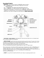
Operating Instructions For the:
Force 10 Monolight PART #11232 (1000 watt-seconds)
Force 5 Monolight PART #11235 (500 watt-seconds)
Table of Contents
General Information / Features / Accessories . . . . . . . . . . . . . . . . 2
General Description . . . . . . . . . . . . . . . . . . . . . . . . . . . . . . . . . . . . 3
Assembly . . . . . . . . . . . . . . . . . . . . . . . . . . . . . . . . . . . . . . . . . . . . 4
Operation . . . . . . . . . . . . . . . . . . . . . . . . . . . . . . . . . . . . . . . . . . . . 5
Normal Mode
Fine Adjustment Mode
Description of Controls . . . . . . . . . . . . . . . . . . . . . . . . . . . . . . . . . 6
Trouble-shooting Guide . . . . . . . . . . . . . . . . . . . . . . . . . . . . . . . . . 8
310 S. Racine Ave.
Chicago, IL 60607
call us: 312/421-4050
fax: 312/421-5079
on the web: www.speedotron.com
email us: [email protected]
General Information:
PLEASE READ AND COMPLY WITH THE FOLLOWING INSTRUCTIONS AND WARNINGS.
• All references to the Force 10 in this manual also apply to the Force 5 unless otherwise stated.
• Unpack and examine all equipment carefully.
• Should you notice any breakage or defect, immediately notify your dealer (and carrier if it was shipped to you). The
flashtube and model lamp are packed in their original cartons. This affords sufficient protection and reduces the incidence
of breakage during shipping. Make sure all packing materials are removed from flashtubes before using. Any plastic pieces
or fluffy covered wires (pipe cleaners) are packing materials.
If you suspect that damage has occurred, do not plug the Force 10 into any electrical outlet.
Warning! High Voltage Present
For your safety, please follow carefully!
• To prevent electrical shock, always unplug monolights when replacing flashtube and model lamp.
• Always use a grounded AC outlet when connecting your power supply.
• Never pull the AC power cords by the cable when removing, and make sure the power is turned off prior to removal.
• Flashtubes and model lamps become very hot when flashing or lighted, so extreme care should be taken when handling
the light or changing accessories.
• Because of the weight of the Force 10 and accessories, a heavy duty, wide based light stand such as the Speedotron
11’ (Part number 15514 or 15515) stand should be used. The 15516 casters allow smooth rolling movement with 11’
stands. Stands should always be sand bagged or weighted at the base with ten pound weights (Speedotron part number
13513) when heavy accessories are attached to monolights.
Never extend heavily loaded stands to full length!
Features:
Standard Features: 1) Photo cell slave 2) Audible and visual 100% ready indication
3) Low voltage sync circuit 4) Cooling fan 5) Visual “fail to flash” indication
6) Automatic Safety circuit discharges capacitors when Force 10 is turned off.
Advanced Features
Microcomputer circuitry enables the following features:
1) Normal (wide range) and Fine Adjustment modes of operation for control of power.
2) Capacitors are monitored and formed when the Force 10 is turned on.
3) Temperature sensing and management.
4) Audible and visual indication of abnormal operating conditions.
5) Communications outlets for future remote control links between other flash units & computers.
Accessories: The full line of Speedotron Universal Light Unit accessories is available for the Force 10/5.
Among these are the following:
12311 Circle Set - Five stainless steel circle patterns used for projecting sharp edged circles. Hole size ranges
from 1.5 inches in diameter down to .125 inches.
12339 6” Variable Focus Zoom Spot - Enables the Force 10/5 monolights to be used as spot lights.
2
General Description:
Power:
Force 10: 1000 Watt/Seconds at full power, yielding a Guide Number up to 540 at
ISO 100 with normal 11.5” reflectors
Force 5: 500 Watt/Seconds at full power, yielding a Guide Number up to 380 at ISO
100 with normal 11.5” reflectors
Recycle:
Force 10: 1.6 seconds to full power on Fast Recycle. 4 to 5 frames per second at
low power. 8 ampere average charge current with 13 ampere peak current on Fast
Recycle, 6 seconds to full power on Low Current Recharge at 4 amperes.
Force 5: 1.6 seconds to full power on Fast Recycle. 4 to 5 frames per second at low
power. 5 ampere average charge current with 9 ampere peak current on Fast Recycle,
3.5 seconds to full power on Low Current Recharge at 3 amperes.
Power
Range:
Normal Mode: Full to -5 f-stops in one third f-stop increments.
Fine Adjustment: Mode: Full to -2.5, or -2.5 to -5 f-stops in 1/6th f-stop increments.
Flashtube:
Color corrected, Frosted shell, High power, Constant 1/850 second flash duration with
Force 10. Constant 1/1500 second flash duration with Force 5, Quartz flashtube
with ventilation holes for fan cooling.
Model Lamp:
250 watt quartz halogen model lamp can be set to track the flash power or operate
brightness. 150 watt quartz halogen normally supplied with Force 5, but 250 watt lamp
may be used.
at full
Weight: Force 10: 8 pounds; Force 5: 6 pounds (without cords or stand mount).
Controls:
A single 16 position dial controls both model lamp and flash intensity.
Three position model lamp toggle switch: On Full/Off/Power Tracking.
Three position rocker switch: Low Current Charge/Fast Charge/Open Flash.
This switch is also used to initiate Fine Adjustment Mode of operation.
Power On /Power Off/Circuit Breaker push button.
Connections:
1) Low Voltage Sync (6 volts for compatibility with digital cameras)
Photo Slave turns off when sync cord is connected
2) Two External Communication outlets 3) AC Power Inlet
Variable Focus Reflectors: Two turns of the Focus Collar changes the beam angle of normal
reflectors from less than 35º to more than 90º, expanding the total guide number
range from 42 to 540 on-axis.
Mounting:
Two built-in, aluminum dovetail channels for attachment of stand mounts. These
versatile dovetails lend themselves to the attachment of large and heavy accessories
or carrying handles. Force monolights may be supported from overhead or blocked
together.
3
Assembly:
Attach the 5/8” STAND ADAPTER to the Force 10 by depressing the stand adapter spring and slide the adapter along the
lower dovetail (Dovetails are the slots on the top and bottom of the Force 10) until the detent button clicks into one of the
dovetail’s five holes. Depress the spring again to move the STAND ADAPTER forward to a position of good balance. The
best balance point varies with the size of the reflectors or accessories attached to the system, but is usually near the
middle of the dovetail. Insure that the TILT HANDLE is tight and the STAND BLOCK is vertical. Mount the Force 10 on a
heavy duty stand and inspect for stray packing materials or other loose objects.
Thread the FOCUS COLLAR onto the Force 10 housing and rotate it clockwise one full turn. The two nylon Reflector
Mounting Buttons must face forward, toward the Flashtube when the collar is properly mounted.
Install the MODEL LAMP into the bayonet socket. Never use a model lamp larger than 250 watts!
Plug the FLASHTUBE into the housing. The four pins will allow the tube to be inserted only one way. Push the FLASHTUBE
firmly until it is fully seated and “clicks” into place.
Always insure that the Force 10 is disconnected from the AC line before replacing a Flashtube!
• Always handle FLASHTUBES and MODEL LAMPS with care. They can break if put under stress.
• FLASHTUBES must be inserted into the sockets all the way. A slight rocking motion may be necessary when installing
some flashtubes. New tubes and sockets fit very tightly.
A reflector or soft box may now be mounted upon the Focus Collar. Align the two semi-circular notches on the back of the
reflector with the Reflector Mounting Buttons and rotate the reflector a quarter turn clockwise until it stops. The Focus
Collar may be rotated up to two full turns to change the reflector’s angle of coverage.
Umbrellas should be used with the 14222 7” Grid Reflector. Rotate the Focus Collar to align the hole in the reflector with
the Umbrella Slot in the Stand Adapter. Insert the opened umbrella through the reflector hole and the Stand Adapter’s
opening, then lock the umbrella in place with the Umbrella Knob.
The yellow sync extension cord connects to the low voltage, round Sync Socket. Connecting a sync cord automatically
disconnects the built-in photo slave. If the Force 10 is to be used as a slaved lighting unit, sync cord must be unplugged
unless an accessory slave is used. (See Slave Sensor in Description Of Controls below for use of an accessory slave).
Plug the sync extension cord into this socket and your camera’s PC cord or hot shoe adapter into the other end of the sync
extension cord.
Insure that the POWER ON/OFF switch is turned off. (When “off”, the square button protrudes from the back of the unit.)
Connect the AC power cord first to the Force 10 and then to a grounded AC wall outlet.
4
Operation
-- Note: Divide Watt-Seconds by 2 when using Force 5.
Normal Mode - Assemble the Force 10 as described in the Assembly section above. Rotate the POWER LEVEL KNOB to
the -5 position. Toggle the MODEL LAMP SWITCH to the right hand (Tracking) position. The SLOW / FAST / OPEN FLASH
switch may be set to either Fast or Slow. Press in the POWER button to turn on the Force 10. The READY LIGHT will
appear as a blinking amber color for several seconds while the system undergoes diagnostic testing and forming. This
period normally lasts only three or four seconds, but if the Force 10 has not been used for several months, the diagnostics
may take as long as two and a half minutes. After this diagnostic period, the READY LIGHT will briefly turn red and the
flashtube will fire. The Force 10 will quickly recharge as indicated by a green READY LIGHT, the illuminated model lamp
and an audible beep. The Force 10 is now ready for use.
Rotate the POWER LEVEL knob to F. The MODEL LAMP will briefly dim and then brighten, and the beeper will sound. This
is the full power position. Press the SLOW / FAST / OPEN FLASH switch to the down position to fire the unit. Note that the
model lamp dims during recharge.
Turn off the Force 10 by pressing the POWER ON/OFF switch. This flashes the Force 10. Set the SLOW / FAST / OPEN
FLASH switch to Fast, and the MODEL LAMP SWITCH to Full (left hand position) and turn power on again. The POWER
LEVEL KNOB may be in any position when power is turned on, so it may be left in the Full power position. Note that after
the diagnostics and initial charge the Force 10 did not flash since it was set at a high power level, and the MODEL LAMP
will be at full brightness. Flash the unit again and the MODEL LAMP remains at full brightness during recharge. The
position of the MODEL LAMP SWITCH at “power up” determines the behavior of the Model Lamp during recharge. See
Description Of Controls below for details covering the functions of the MODEL LAMP SWITCH.
The Force 10 incorporates an automatic discharge circuit. The energy stored in the capacitors is reduced by one of two
methods when a lower power level is selected. If the POWER LEVEL KNOB is turned down by a small increment, such as
1/3 f-stop, an internal discharge circuit will immediately dump the excess energy. If, however, the POWER LEVEL KNOB is
turned down by a greater amount, the internal circuits would take a longer time to accomplish the level change. To prevent
this delay, the Force 10 will flash to quickly dump the excess energy into the flashtube and recharge to the newly selected
power level.
Fine Adjustment Mode - Shut off the Force 10 by pressing the POWER ON/OFF switch. Hold the SLOW / FAST /
OPEN FLASH switch in the OPEN FLASH position while turning on power. Holding down the OPEN FLASH switch during
“power up” places the Force 10 into the FINE ADJUSTMENT MODE of operation. FINE ADJUSTMENT MODE is used when
very fine (1/6 f-stop) adjustments are to be made to the Model Lamp and flash intensity, such as those which may be
required in Digital Imaging. Fine Adjustment Mode is indicated by an Amber colored Ready Light.
FINE ADJUSTMENT MODE divides the power range into upper and lower halves to attain fine levels of precision. The lower
half covers the range of 31 Watt/Seconds to 175 Watt/Seconds, and the upper half covers 175 Watt/Seconds to 1000
Watt/Seconds. When in Fine Adjustment Mode, every two whole numbers equals one full f-stop. This means that rotating
the POWER LEVEL KNOB from F to -2 reduces power one f-stop in 1/6 f-stop increments.
The position of this knob when turning on power in Fine Adjustment Mode determines whether the Force 10 operates in
the upper or lower power ranges. If it is in any position from -5 through -2 2/3 during turn on, the lower Fine Adjustment
Mode range is used (31 Watt/Seconds to 175 Watt/Seconds). If the knob is from -2 1/3 through F, the upper Fine
Adjustment Mode range is used (175 Watt/Seconds to 1000 Watt/Seconds). To change from one range to the other, turn
off the Force 10, rotate the POWER LEVEL KNOB to select the lower or upper range, then turn on the unit again.
The Model Lamp brightness also varies with the choice of lower or upper power ranges. The lower range limits Model
Lamp brightness to half power when the MODEL LAMP SWITCH is set to Full or Tracking.
5
Description Of Controls:
• READY LIGHT A three color light that displays the Force 10’s condition of readiness.
Green - The Force 10 is in Normal mode and fully charged to the level set by the
POWER LEVEL KNOB.
Red ---- The Force 10 is either charging or discharging to different power level.
Amber.- The Force 10 is in Fine Adjustment Mode and fully charged to the set level.
Blinking Amber, No audible beep - Occurs during start up. The Force 10 is undergoing normal
diagnostic tests & capacitor forming. This lasts from about three seconds up to 2-1/2 minutes.
Blinking Green, Red or Amber accompanied by audible beeping. See TROUBLE-SHOOTING GUIDE.
• POWER ON/OFF / CIRCUIT BREAKER Overload protection is built into this push button switch. If an overload should
occur, the button will pop out to the Off position.
• POWER LEVEL KNOB A single 16 position dial controls both model lamp and flash intensity. The power level is directly
indicated by the red colored dial when using Normal Mode of operation. Rotating the knob one whole number (such as
from -2 to -1) changes the power one full f-stop in 1/3 f-stop increments.
When in Fine Adjustment Mode, every two whole numbers equals one full f-stop.
This means that rotating the knob from F to -2 reduces power one f-stop in 1/6 f-stop increments.
When turning on power in Fine Adjustment Mode, the position of this knob determines whether the Force 10 operates in
the upper or lower power ranges. If it is in any position from -5 through -2 2/3 f-stops during turn on, the lower Fine
Adjustment Mode range is used (31 Ws to 175 Ws). If the knob is placed anywhere from -2 1/3 through F during turn on,
the upper Fine Adjustment Mode range is used (175 Watt/Seconds to 1000 Watt/Seconds).
Please refer to OPERATION above.
• AC INLET - Use only 105 to 130 volts 50 to 60 Hz AC current. Always use a properly grounded line cord.
6
• SYNC SOCKET A low voltage, quarter inch round phone jack. Connecting a sync cord automatically disconnects the builtin photo slave. If the Force 10 is to be used as a slaved lighting unit, the sync cord must be unplugged. Plug the sync
extension cord into this socket and your camera’s PC cord or hot shoe adapter into the other end of the sync extension
cord.
• UMBRELLA SLOT - Accepts standard Speedotron umbrellas and accessories.
• UMBRELLA KNOB - May be used to lock umbrellas in position.
• SLAVE SENSOR - Flashes the Force 10 when other flashes are fired. Insert sync cord to disable the photoslave.
The photo slave is highly sensitive to the light of other flash units, but there are occasions when the lighting
arrangement requires a Force 10 to be located so that the SLAVE SENSOR is obstructed causing the Force 10 to unreliably
fire or not fire at all. Connecting an external photo slave to the end of a sync extension cord and placing this slave in an
unobstructed position will resolve this predicament.
• SLOW / FAST / OPEN FLASH A three position rocker switch determines rate of charge. The upper position selects Slow
charge for use when multiple Force 10s are connected to a single circuit or a portable generator. The center position
selects Fast Charge. The lower position produces an Open Flash. The Open Flash position of the switch is spring loaded to
return to Fast Charge when released.
A recharge rate switch that springs to the Fast Charge position will result in that Force 10 recharging at the Fast
Charge rate. This may be an undesirable situation with multiple Force 10s on the same circuit recharging at one time. This
situation may be avoided by manually holding the switch in the Open Flash position. As long as the switch is held in the
Open Flash position, the Force 10 will not recharge. This procedure allows the other Force 10s on the circuit to recharge
without being affected by Fast Charge current from the manually operated Force 10. The switch may be returned to the
SLOW position at any time, even during recharge.
Fast is the normal charging rate for Force 10s when sufficient AC power is available. Typically, at least one and in
some cases two Force 10s can operate on a single 15 ampere AC line in the Fast charge position. If two or three units are
to be powered from the same 15 ampere AC source, Slow charge should be used. Setting the Model Lamp to dim or turn
off during recharging is helpful not only in reducing AC current requirements, but it also serves as a “Fail-to-flash”
indicator. (See MODEL LAMP SWITCH below)
• MODEL LAMP SWITCH A three position toggle - On Full, Off and Power Tracking.
The left position sets the model lamp to Full brightness regardless of the setting of the POWER LEVEL KNOB in
Normal Mode. Center is the Off position. The right hand position denotes Tracking. Tracking means that the model lamp
brightness is determined by the POWER LEVEL KNOB.
The position of the MODEL LAMP SWITCH as the Force 10 is turned on determines whether the model lamp dims
during recharge. If in the Off position when the Force 10 is turned on, the model lamp will turn off during recharge. If in
the Tracking position, the model lamp will dim during recharge. If the MODEL LAMP SWITCH is in the Full position when
power is turned on, the model lamp will not dim while recharging. After the initial “power up”, the MODEL LAMP SWITCH
may be set in any position without affecting the Model Lamp’s dimming during recharge.
The Model Lamp may be used as a “Fail-to-flash” indicator when it is set to dim during recharge. If multiple Force
10s are used in a complex lighting arrangement, it may be difficult to know whether all have flashed when they are slaved
together. It is therefore a good practice to place the MODEL LAMP SWITCH into the Off or Tracking positions when
“powering up” slaved lighting units. In this situation a Model Lamp remaining at full brightness during recharge reveals
that it’s Force 10 did not flash and the unit should be repositioned to insure that the photo slave is not obstructed.
• POWER INDICATOR - An illuminated index line on THE POWER LEVEL KNOB marking flash and model lamp settings.
• COMMUNICATIONS OUTLETS - Two eight pin RJ-48 connections used for future communications with remote controls,
other Force 10s and computers.
7
Trouble-Shooting Guide:
If an abnormal condition should appear, the Force 10 provides several indications to assist the photographer in correcting
the situation. Among these are:
• High Temperature - If the operating temperature of the Force 10 should reach 90% of its Shutdown temperature, the
unit will go into high temperature alarm condition. This consist of displaying the following indications:
• Blinking READY LIGHT - The color of the READY LIGHT will remain the same as it would in normal operation Green if in Normal Mode, Amber if in Fine Adjustment Mode or Red if the unit is recharging; but the READY LIGHT
will continuously blink.
• Audible beeping - (Beeps twice every two and a half seconds.)
• Model Lamp - Brightness of the Model Lamp modulates from bright to dim if it is in either the Full or Tracking modes.
If the temperature drops to a safe level, the alarm will automatically clear and the behavior of the Force 10 will return to
normal.
• Thermal Shutdown - Excessively high temperature will cause a Force 10 to stop operating.
This condition is designated by:
• Blinking RED READY LIGHT
• Audible beeping - (Beeps three times every two and a half seconds.
• The Force 10 does not recharge
• The Model Lamp will not turn on
If the temperature drops to a safe level, the alarm will automatically clear and the behavior of the Force 10 will return to
normal.
• Diagnostic Test Failure - If the Force 10 were to fail the self diagnostic tests when starting up,
the following indications would be displayed:
• The READY LIGHT would turn to a solid (non-blinking) Red color
• Audible beeping - (Beeps three times every two and a half seconds.
• The Model Lamp would operate normally
If the Force 10 repeatedly fails the start up diagnostic tests, it should be sent to Speedotron for service.
8