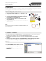
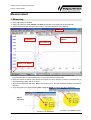
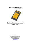
1
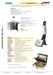
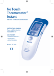
WALKING TEST KIT WT5000
reliable & caring since 1976
Walking Test Kit, includes:
a WT5000 electrometer, A/D converter with software, hand-held probe, connecting cables, conductive carrying case,
user’s instruction in German and English and calibration certificate. The graph of the body voltage measurement will be
displayed „online“ on the connected PC or LAPTOP.
Electrometer WT5000:
•T
est range: ± 5.000 volts or ± 500 volts
•A
ccuracy: 5% of measured value
• Input resistance:
> 1014 ohm
• Input capacitance: < 5 pFarad
•D
isplay: Logarithmic LED-display ± 500 volts, changeable
to ± 5.000 volts, Peak hold
•O
utput: Analog ± 5 volts for each test range
•O
peration: Rechargeable batteries
(battery charger included)
Complies with IEC 61340-4-5
TEST AND MEASUREMENT
Includes:
• Electrometer WT5000
• A/D converter UAD1 with USB connector
• Data acquisition and analysis software "Digilloscope"
for Windows®
• Handheld probe
• Teflon® insulated cable
• 4 NiMH rechargeable batteries
• Charger
• Conductive carrying case
Part Nr.
7100.WT5000.B
Walking Test Kit - USB-Version
Product link
WALKING TEST BODY VOLTAGE MEASUREMENT
Body voltage measurement test set-up.
The new software “Digilloscope" can mark the
five highest peaks automatically and calculates the average value.
ANALOG/DIGITAL CONVERTER
The UAD1 can be used with the following instruments:
• WT5000 (see above)
• ESVM1000 and ESVM2000 (see page 80)
• includes Data acquisition and analysis software
"Digilloscope" for Windows®
Part Nr.
7100.UAD1 Analog/Digital converter with USB connector - UAD1
User's Manual
Walking Test Kit
7100.WT5000
Wolfgang Warmbier
Untere Gießwiesen 21
D-78247
Hilzingen/Germany
www.warmbier.com
Walking Test Kit Operating Instructions
Part No. 7100.WT5000
_
Table of contents
Overview ................................................................................................................................................. 2
Technical data ........................................................................................................................................ 3
Operation ................................................................................................................................................ 3
Controls and displays ..................................................................................................................... 3
Function keys ................................................................................................................................. 4
"Peak Hold" function....................................................................................................................... 4
Measuring range............................................................................................................................. 4
Trouble Shooting ................................................................................................................................... 4
Only a horizontal line is visible after starting the measurement..................................................... 4
Your computer does not have the parallel port to insert the A/D-Converter .................................. 4
Maintenance ........................................................................................................................................... 5
Battery charging and replacement ................................................................................................. 5
Zero adjust...................................................................................................................................... 5
Warranty ......................................................................................................................................... 5
Notice ...................................................................................................................................................... 5
Calibration .............................................................................................................................................. 5
Preparation ............................................................................................................................................. 6
Connecting the components........................................................................................................... 6
Software installation ....................................................................................................................... 6
Setup .............................................................................................................................................. 6
Measurement .......................................................................................................................................... 7
Measuring ....................................................................................................................................... 7
Overview
The Walking Test Kit described below, is used to monitor the body voltage on a person. The voltage is
taken from the electrometer through the A/D-converter and displayed on a PC or a laptop.
The kit consists of:
•
Electrometer WT5000
•
Analog/Digital-Converter Pico 42M
•
Data acquisition an analysis software PicoScope
•
Handheld probe
•
Connecting cable and plugs
•
Conductive carrying case
Page 2 / 7
Edition: Nov. 2006
Walking Test Kit Operating Instructions
Part No. 7100.WT5000
_
Technical data
Electrometer
Dimensions:
Weight:
Input voltage:
Input impedance:
Input capacity:
Response time:
Output:
Display:
Power supply:
Operating time:
Charger:
Ranges:
Accuracy:
Battery monitoring:
190 x 148 x 67 mm (L x W x H)
ca. 500g
± 500V / ± 5000V
14
> 10 Ω
< 5 pF
≤ 10 ms
Analog ± 5V
21-digit logarithmic LED display with "Peak Hold"
4 pcs. NiMH rechargeable batteries (AA)
4 to 6 hours
7,5V DC, 300 mA
± 500V, ± 5000V
< 5%
audible
A/D-Wandler
Input impedance:
Interface:
Input voltage:
Resolution:
Max. sampling rate:
Power supply:
1 MΩ
Parallel printer port, (USB with optional adapter)
± 5V DC
12 Bit
15 kHz
via printer port
Operation
Controls and displays
Front side
( 1 ) Measurement input
Back side
(7)
On-/off button
(2)
Input range indicator LED x10
(8)
Power supply socket for the charger
(3)
Input range selector
(9)
Grounding socket
(4)
Trimmer for zero adjustment
( 10 )
Analog output (BNC socket) - Analog
signal for the A/D-converter
(5)
"Peak Hold" reset button
(6)
21-digit logarithmic LED display
Page 3 / 7
Edition: Nov. 2006
Walking Test Kit Operating Instructions
Part No. 7100.WT5000
_
Function keys
On/Off ( 7 )
Button to switch the instrument on and off.
A beep signal sounds on power on.
When not used, the instrument switches off automatically after 15 minutes.
Range ( 3 )
Selects input range ±500V or ± 5000V. The higher range is indicated by the
green "x10" LED
Reset ( 5 )
Resets the "Peak Hold" display
"Peak Hold" function
The last measured positive and negative peak value is held on the LED display until it is reset with the
"Reset" button.
Measuring range
The two measuring ranges can be switched with the "Range" button.
When switched on, the instrument's range is ± 500V. Pressing the "Range" button will switch to ± 5000V.
The according range is displayed by the green x10 LED.
Changing the range will also change the output resolution of the analog output. This has to be
taken into account during measurement.
Range
± 500V
± 5000V
Output
± 5V
± 5V
Multiplier
100
1000
Trouble Shooting
Only a horizontal line is visible after starting the measurement.
For proper A/D-Converter operation the Parallel port of the computers BIOS must be set to Normal,
Unidirectional or SPP. Please check the BIOS setting.
To enter the BIOS setup press and hold one of the keys DEL, F1 or F2 Taste while switching the
computer on.
Your computer does not have the parallel port to insert the A/D-Converter
You can use the optional available USB to Parallel Converter Part No. 7100.WT5000.USB to
connect the A/D-Converter to the USB-Port.
Page 4 / 7
Edition: Nov. 2006
Walking Test Kit Operating Instructions
Part No. 7100.WT5000
_
Maintenance
Battery charging and replacement
An audible signal indicates a battery low state. Plug in the power supply to charge the battery when
necessary. The battery is located inside the battery compartment underneath the instrument.
Only NiMH rechargeable batteries Type (AA) are allowed for this instrument!
Zero adjust
Zero adjusting is normally not necessary. If the unit does not indicate 0V while the input is connected to
ground, the zero adjustment trimmer (4) can be used to for adjustment.
Warranty
Warranty does not include the NiMH rechargeable battery, damage of the battery due to drain, and
mechanical damage of the instrument.
The warranty is void if the unit was opened.
Notice
•
•
•
•
This instrument is not approved for measurements in explosion hazard areas.
The electrometer must always be grounded during measurement.
Using the instrument in power plants is not permitted.
The electrometer is not equipped to detect alternating fields > 100 Hz.
Calibration
The recommended calibration interval is 2 years.
Page 5 / 7
Edition: Nov. 2006
Walking Test Kit Operating Instructions
Part No. 7100.WT5000
_
Preparation
For data acquisition and storage the PicoScope software has to be installed on a Computer with Windows
operating system and the A/D-converter must be connected to the parallel port.
Connecting the components
1. Plug the A/D-converter into the 25-pin D-SUB socket of your
computer's printer interface LPT1.
2. Connect the A/D-converter to the electrometer using the
BNC-cable.
3. Connect the earth terminal of the electrometer to earth using
the crocodile clip of the grounding cord.
4. Connect the handheld probe to the electrometer using the
Teflon-insulated wire.
5. Charge the battery of the electrometer with the external power
supply if required.
Note:
The computer must be connected with the electrometer during the
whole measurement.
Software installation
♦ Run the installation program webpsw32.exe on the enclosed CD-ROM. If your operating system is
Windows NT, XP or 2000 you must run the setup program as administrator.
♦ After selecting your language you have to confirm the license agreement and select a path for
installation.
♦ After that you are asked to select your Operating System, the Product ADC-42 and port LPT1.
♦ The software group PicoScope should be checked. After specifying a program group the installation
is completed. You must restart your computer before running the program.
Setup
♦ Run the PicoScope program and load the initial
setup file with File - Open.
♦ Select the CD-ROM drive and open the file
wt5000_setup.psd.
♦ To store the settings permanently, select File Safe Settings.
Page 6 / 7
Edition: Nov. 2006
Walking Test Kit Operating Instructions
Part No. 7100.WT5000
_
Measurement
Measuring
♦ Set the X-Scaling to 1s/Unit
♦ Set the Y-Scaling to either ± 5000V or ± 500V appropriate to the setting of the Electrometer.
♦ Start measurement with the green GO-button in the lower left corner of the window.
Zoom
Cursor distance
249 ms
x= Cursor 1
o= Cursor 2
Start- / stop button
♦ Perform the Walking Test and stop measurement afterwards with the red STOP button. The
measurement data is rolling continuously on the screen during measurement.
♦ Move the cursors as shown in the picture to measure the curve. Drawing a vertical or horizontal line at
the appropriate position will set a cursor.
♦ Store the measurement with File - Save. Choose Drive «C:», file-type «Data Files (PSD)» and enter a
filename.
♦ Copy the graph to the clipboard using Edit - Copy as Graph to insert it into other applications.
Adjust
Y-Scaling
Function "x10" not active
Page 7 / 7
Function "x10" must be active
Edition: Nov. 2006