1
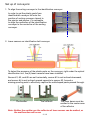
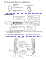
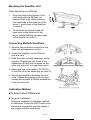
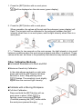
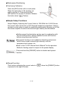
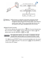
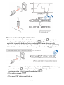
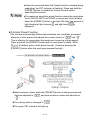
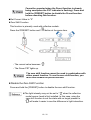
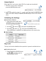
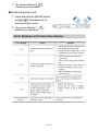
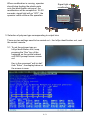
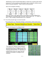
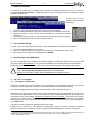
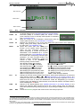
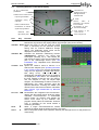
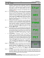
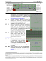
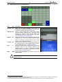
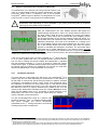
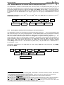
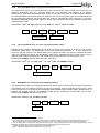
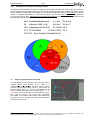
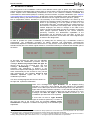
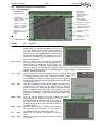
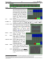
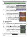
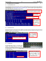
Operation Manual Plastic Identification and Sorting Plant Model: sIRoSort Rev: 104-04 GUT GmbH Birkenwaldstr. 90 70191 Stuttgart Germany Tel. +49 711 2573979 Fax +49 711 2573934 e-mail: [email protected] www.gut-stuttgart.de Benefitek Co., Ltd. Taipei, Taiwan Tel. +886 2 2755 6137 Fax +886 2 2755 0145 Mobile: +886 935 163 588 +886 926 309 589 Email: [email protected] Operation manual of sIRoSort Safety: 1. On the identification conveyor and drop conveyor Unless for maintenance, always leave the cover of ceramic plates mounted at the inlet. In case of cover of ceramic plate is removed, the ceramic plate at the turning point at inlet and outlet may hurt operator’s finger when contacted the turning points of the conveyor. X Identification conveyor Unless for maintenance, always leave the cover of the sprocket drive box mounted 2. On the drop parts conveyor X Drop conveyor Unless for maintenance, always leave the cover of the sprocket drive box mounted 1 / 12 Set up of conveyors: 1. To align the sorting conveyor to the identification conveyor In order to get the plastic parts from identification conveyor fall onto the position of sorting conveyor closest to the ejector and pusher, it is advisable to align the centerline of the identification conveyor to the centerline of the sorting conveyor. Center Center 2. Laser sensors on identification belt conveyor To detect the presence of the plastic parts on the conveyor, right under the optical identification unit, five(5) laser sensors have been installed. Sensor #1, #2, and #5 are set horizontally, sensor #3 is set inclined downward, and sensor #4 is set inclined upward opposite to sensor #3, formed a missing-proofing web to effectively capture the odd-shaped pasts passed through. The emitter The reflector The laser beam must be emitted in the center area of the reflector Note: Neither the emitter nor the reflector of laser sensor can be wetted, or the mal-function will occur 2 / 12 The Transmitter, Receiver, and Reflector The Amplifier *1 This is a power select switch on M8 connector types or monitor output types. Not available for 0-line types. *2 Press and hold the [MODE] button to make advanced setting changes. 3 / 12 Mounting the Amplifier Unit When Mounting on a DIN Rail 1. Align the claw at the bottom of the main body with the DIN rail, as shown on the right. While pushing the main body in the direction of the arrow 1, push down in the direction of arrow 2. 2. To dismount the sensor, raise the main body in the direction of the arrow 3 while pushing the main body in the direction of arrow 1. Connecting Multiple Amplifiers 1. Remove the protection covers from the main unit and expansion unit(s). 2. Install the amplifiers on the DIN rail, one at a time. 3. Slide the main unit and expansion unit(s) together. Engage the two claws of the expansion unit with the recesses on the main unit side until you hear/feel a click. 4. Attach the end units (option: OP-26751) to the DIN rail in the same way as step (2). 5. Secure the amplifiers between the end units. Tighten the screws at the top (two screws per unit)with a Phillips screwdriver to fix the end units. Calibration Method ■To Detect Small Differences ●Two-point Calibration Two-point calibration is the basic method of calibration. Press the [SET] button once without the work piece, and then press it once again with the work piece. 4 / 12 DIN Rail 1. Press the [SET] button with no work piece. [ ] will be displayed on the sub-menu (green display). 2. Press the [SET] button with a work piece. When complete, the values will be set and the submenu (green display) will flash. The set point will be calibrated to the mid-point between the light intensity when there is no work-piece, and the light intensity when there is a work piece. If "----" flashes for two seconds on the main screen, the light intensity is too small between conditions when the work piece is absent and when it is present. These values will be set, but there is the possibility that detection may become unstable. Other Calibration Methods ■Increased Resistance to Dust and Dirt ●Maximum Sensitivity Calibration In the state shown as sketch on right side, press and hold the [SET] button for three seconds or more. Stop pushing when " " flashes. The sensitivity is set slightly higher than the received light intensity. ■Calibrate with a Moving Workpiece ●Full Auto Calibration Press and hold the [SET] button with no " is work piece in place. While " flashing, pass a work piece through. (Continue pressing the [SET] button while the work piece passes through.) 5 / 12 ■Work piece Positioning ●Positioning Calibration Press the [SET] button with no work piece. Place the work piece in the location you wish to position it. Press and hold the [SET] button for at least 3 seconds. Release the button when " " flashes. ■Simple Setup Functions Simple Display: Adjusting the Current Value to 100.0With the LV-N10 Series, the current value can be set to 100.0 through simple key operations. Using a constant current value is useful for predictive maintenance allowing you to find the sensor amplifier for which the received light intensity has decreased. ●Neither preset function below can be used in combination with the zero shift function. Always disable the zero shift function before using the preset function. ●The preset function is not suitable for detecting work pieces Which have a small received light intensity, such as transparent work pieces, etc. ●Refer to the "LV-N10 Series User's Manual" for the operation Method of analog output in respect to the preset display. Press and hold the [PRESET] button to disable each preset function. ●Preset Function This function calibrates the current value to " is pressed in the light-ON state. 6 / 12 " when the [PRESET] button ●This function is especially useful when performing simple detection(sensor beam completely interrupted by a nontransparent object)using the thru-beam model / retro-reflective model sensor heads. When using multiple Neo Series units, the display can be easily standardized with this function. ●Target-Preset Function This function calibrates the current value to ". ". After the preset function has been executed to display " ", execute this function to display ". ". Two random points can be calibrated to " If the " and ". ". button and [PRESET] button are pressed simultaneously, the current value is set to ". " at that point. The value set to " function does not change. 7 / 12 " with the [PRESET] ●Maximum Sensitivity Preset Function This function sets conditions that will serve as reference to ". " and adjusts conditions with slightly higher light intensity to " ". This is useful when you would like to perform detection using the background as a reference with reflective models. Under the following conditions, press and hold the [PRESET] " flashes. button for 3 seconds or more. Then release your finger when " ●The maximum value for the light intensity while the [PRESET] button is being pressed is set to ". ", and light-intensity that is slightly higher than the maximum value at that time will be adjusted " ". ●The setting value is " " ●The green PST indicator will light up. 8 / 12 ●Cannot be executed when the Preset function is already being used(when the PST indicator is flashing). Press and hold the [PRESET]button to disable the Preset function before executing this function. ●The maximum sensitivity preset function cannot be used when the LV-NH100, NH110 or NH300 is connected, but by holding down the [PRESET] button in the light ON state, the amount of light blocked at light intensity. displayed. and light block is ●Full Auto Preset Function This function automatically differentiates between two conditions (presence/ absence of work piece) and adjusts the current values to " " and ". ". This is effective for cases when the work piece is moving at high-speed. Press and hold the [PRESET] button with no work piece in place. While " " is flashing, pass a work piece through. (Continue pressing the [PRESET] button while the work piece passes through.) ●Near-maximum values while the [PRESET] button is being pressed and held are adjusted to " ". " and near-minimum values are adjusted to ". ●The setting value is changed to " " ●The green PST indicator will light up. 9 / 12 Cannot be executed when the Preset function is already being used(when the PST indicator is flashing). Press and hold the [PRESET] button to disable the Preset function before executing this function. ■Set Current Value to "0" ●Zero Shift Function This function is primarily used with reflective models. Press the [PRESET] button and [ ] button at the same time. •The current value becomes ". ". •The Green PST lights up. The zero shift function cannot be used in combination with either preset function. To use the zero shift function, you must first disable the preset function. ●Disable the Zero Shift Function Press and hold the [PRESET] button to disable the zero shift function. ●The light intensity may not be set to ". " when the reflective model sensor head is first installed. In this case, using the zero shift function to set the state with no target present to ". " will make it easier to see the difference in light intensities. 10 / 12 Output Switch Either light-ON (L-on) mode or dark-ON (D-on) mode can be selected. 1. While the current value is displayed, press the [MODE] button once. 2. Use to switch the output ( / ), then press the [MODE] button again. The output change completes, and the display returns to the current value. Initializing the Settings ■Initialization Method 1. Press and hold the [SET] and [PRESET] buttons simultaneously for more than three seconds. 2. Use the to select " ", then press the [MODE] button. 3. Use the to select " ", then press the [MODE] button. After initialization is complete, the display returns to the current value. Key Lock The key lock function disables button operation to prevent unauthorized use. ■Activating Key Lock 1. Press and hold the [MODE] button and (or ) simultaneously for three seconds or more. 11 / 12 2. The screen displays " ", disabling key operation. ■Deactivating Key Lock 1. Press and hold the [MODE] button and (or ) simultaneously for three seconds or more. 2. The screen displays " enabling key operation. ", 12 / 12 Operation of control console 1. Outline of touch screen Position of Photo sensor Speed of identification conveyor 5~20 minutes can be set Speed of sorting conveyor 2. Start and Stop button Start button Stop button 3. Emergency stop buttons There are total five(5) emergency stop buttons distributed on the identification and sorting conveyors. In case of emergency, press down anyone of it, conveyor will be stopped. Upon emergency case is settled, twist the cap of the button, it will be resumed. Position of five emergency stop buttons on conveyor 2. Recalibration In order to maintain the minimal accurate identification result, it is advisable to set an interval of recalibration. After pressing the green “Start” button, the operation runs till the interval set is up, the light come “ON and Flash”, the recalibration of identification unit takes place, and the display of monitor screen change, however, conveyors will not stop. 1/3 When recalibration is running, operator should stop feeding the plastic parts onto the identification conveyor; the recalibration will be complete in 15~20 seconds, signal light will go “OFF”, the operator could continue the operation. Signal light of recalibration Optical cabinet 3. Selection of polymer type corresponding to output bins There are two settings need to be carried out – the IoSys identification unit, and the control console. 3-1. To set the polymer type on IoSys Identification unit, keep pressing the “Esc” key of the keyboard on the optical cabinet until DOS prompt screen comes out. Key in the command “edit ini.dat”, then “Enter”, the display below on the screen is seen. 2/3 Identification mode is selected dependent on what form of plastic parts will be processed. For the complex of mixed plastic parts include the industry waste and/or household plastics, “HPng” mode is recommended. Here is an example of setting – Move the cursor to the right position of the screen to get the setting done, upon selection of polymer type is finished, hold the keys “Alt” + “F”, then “X”, and “Y”(Yes), setting of Identification unit is complete. 3-2. To set the polymer type on control console By pressing the icon “Parameter Setting” on the bottom of the touch screen, D screen will change to the display below - The sequence of polymer type displayed in the blocks from “A” though “F” must be identical to the setting of identification unit. Pressing the block of bin “A”, the library of polymer type comes out, press the one selected, the display is changed to the selected. 3/3 Table of contents 1 Enter new Password............................................................................................................. 1 2 Time and Date Setting .......................................................................................................... 1 3 Data Exchange using USB-Stick.......................................................................................... 1 4 The sIRoSlim-program ......................................................................................................... 1 4.1 Conventions in this Manual ............................................................................................................1 4.2 Operating Elements in the Start-Display .......................................................................................2 4.3 Operating Elements in the Result Display.....................................................................................3 4.4 Operating Elements in the Teach-In Menu ....................................................................................5 4.5 Operating Elements in the KEYS Mode .........................................................................................6 4.6 Polymer Type Identification by Neuronal Networks .....................................................................7 4.6.1 The Min-Pxl statement ................................................................................................................7 4.6.2 Standard Model (All, for coloured, natural or milky-like plastic parts):........................................8 4.6.3 HaiPing Model with Sty4 function (HPng, for almost all plastics):...............................................8 4.6.4 Gray Type Model (gryT, for gray-coloured plastic parts):): .........................................................9 4.6.5 Clear Type Model (clrT, for clear, transparent plastic parts):......................................................9 4.6.6 DSD Model (for household and packaging plastics):..................................................................9 4.6.7 Composition of Styrene-containing Polymers ...........................................................................10 4.7 Polymer Type Identification by PLS .............................................................................................10 4.8 Recalibration of sIRoSlim..............................................................................................................11 4.9 Operating Elements in the SPC Mode..........................................................................................12 4.9.1 The Main Menu .........................................................................................................................12 4.9.2 The Shift Menu..........................................................................................................................13 4.9.3 The Bottom Menu .....................................................................................................................14 4.9.4 Additional Operating Elements .................................................................................................14 5 The System Files for sIRoSlim........................................................................................... 15 5.1 The Initialization File......................................................................................................................15 5.2 The Teach-In File............................................................................................................................15 5.3 The Dat-Files...................................................................................................................................15 Manual: sIRoSlim 1 -1- Copyright by Enter new Password The system is secured with a password which activates the sIRoSlim-program (miro.exe). In case the message: Program deactivated!… is displayed, please contact [email protected] to obtain the actual password for the device. To edit once the new password please proceed as following: 1. Connect an external keyboard (PS/2) and a VGA screen to the system. 2. Edit on the DOS-prompt level of the given sub-directory the command line edit ini.dat 3. Replace the 8 stars (*) in the first line of the ini.dat with the new password (8 small characters!). 4. Save the ini.dat file (ALT+F(ile), ALT+S(ave)) and close the Text-editor (ALT+X(exit)). 5. Edit on the DOS-prompt level miro.exe to start the program. 2 Time and Date Setting To enter a new Time and/or Date for example for correct Mini-Plotter printouts please do as follows: 1. Connect an external keyboard to the system. 2. Enter on the DOS-prompt level of the given sub-directory the command time or date, resp.. 3. Edit new date or time values and confirm/quit with <ENTER>. 3 Data Exchange using USB-Stick For data exchange with other computers and software updates an USB stick can be connected to the USB 1 port of the system. Before booting up the system the USB-Stick must inserted correctly into the USB slot. Access to the USB-stick can be done by the means of an external keyboard and by editing <d:> usually. 2 ! 4 4.1 Sometimes there is no access to the USB-Stick at first time and the following error message is shown: Unzulässiger Datenträgertyp beim Lesen von Laufwerk D: Quit the error message by editing <w> like (W)iederholen to repeat the access. The sIRoSlim-program Conventions in this Manual The device is designed in such a way that it can be operated from the touchscreen and/or from an external keyboard. In general a keyboard permits the menu-guided software to be handled more easily. The following paragraph gives the writing conventions used in these operating instructions: Operations to be carried out via touchscreen (optional feature) are given with the legend on the respective touch field and the word <Icon>. Those to be carried out with the external keyboard with the legend of the keyboard key and the word <Key>. Usually small characters should be entered. A touch field on the display only has to be touched briefly. If a number of keys or, as the case may be, touch fields have to be pressed simultaneously, then this is indicated with a plus sign (+) between the individual key or touch field legends, e.g. <SHIFT>+<F1>. In general only small characters of the keyboard are to be used! Pressing a key or touching an icon activates or deactivates a mode or function. In general a repeated pressing the same key or touching the same icon again deactivates/activates the operation, respectively. 1 The USB stick will be recognized by the MS-DOS system at time of booting only ! When the USB stick is disconnected while system operation and connected again then it will not recognize the USB stick again. The unit must be restarted again. German based MS-DOS is used. 2 Manual: sIRoSlim 4.2 -2- Copyright by Operating Elements in the Start-Display Main menu bar Main window Status window Icon Key SPEC F1 RUNS CAL KEYS Mode PLS NetD QUIT Function Switches to SPC mode to view the NIR-Spectra or the transformed Net-Data and to carry out further features (see: Operating Elements in the SPC Mode). 3 F2 Decreases (<F2>) or increases (<F3>) the number of runs (scan numbers) to form an average mean spectra for evaluation (see: The Bottom Menu). F4 Starts the routine for the recalibration measurement with the ceramic plate reference (see: Recalibration of sIRoSlim) F5 Displays the assignment of the touch panel fields and opens further menu options for testing, setting and editing systems files for the mIRo (see: The Initialization File). F6 Opens and closes (also with <ESC>) the function for the fastest Online identification option. No time consuming graphics for spectra displaying is needed and therefore deactivated. In the FastMode up to 7 preset polymer types (see: The Initialization File) can 4 be counted with corresponding external signal generation. If a value exceeds 99.999 or by selecting another identification model the counter is reset. In the FastMode the following Hotkey functions exists: <g> grayType (gryT) activated <a> Standard model (All) activated <c> clearType model (clrT) activated <d> DSD-model activated <h> HaiPing-model (HPngT) activated <s> Sty4-model (4 Styrene types) activated <1> Modifying PA (Polyamid) results <2> Modfiying PO (Polyolefine) results <3> Modifying Styr (Styrene) results <4> Modfiying PES (Polyester) results <5> Modifying PC (Polycarbonat) results <6> Modfiying PVC (Polyvinylchlorid) results <F2> Decreasing amount of scans /runs < > Reset of counter <F3> Increasing amount of scans /runs <ESC> / <F6> Quitting FastMode F7 Changes to the PLS model (Partial-Least-Square), where plastic identification is performed using selected Teach-In samples (see: Operating Elements in the Teach-In Menu). The activation of the PLS mode is displayed on the top and the ranking list appears now in blue letters and the icons to select the identification model are disappearing (no function). Pressing again the <PLS> icon switches back to the Neuronal network calculation and the hit list is displayed in red letters . F8 Switches to the Result-Window (see: Operating Elements in the Result Display). In the NetD-mode (Network Data) transformed and auto scaled intensity data are displayed. Leave the Result-window by pressing any key or by touching the middle of the touch screen briefly. ESC Leaves the sIRoSlim program and returns back to the DOS prompt level. 3 The higher the scan number (RUNS), the better the resulting average spectra (improved signal/noise ratio of the calculated mean), the more stable is the identification result. However, the measuring time takes longer. On the other hand, the smaller the scan number, the more noisy the resulting spectra for evaluation, the less stable is the identification result. On the other hand the measuring time takes shorter. 4 Due to the very fast online measurements in the FastMode the identification result is only shown and counted and the external signal by relay is only generated if the identification result is two times the same successively. Manual: sIRoSlim 4.3 -3- Copyright by Operating Elements in the Result Display Main Menu bar Hit list of identification probabilities Activation of the Online function Polymer type identified Automatical USB-Stick saving at Displaying amount of NIR-light Overflow measurements Select identification model Editor for USB-file name Teach-In Menu to save/select own samples for PLS-method De-/activation of external signal output generation De-/activation of LCDTouchscreen-Display Measured NIRlight intensity level Icon Signal Key Pixel Number of curve minimum the Starts a single scan Function De-/activates the external signal output generation using the 7 internal relays and red LEDs. Results are only shown at the display without signal output (relay closer contact). USB-Edit Enter Opens the menu to edit the main file name (max. 4 characters) for the automatic spectra saving onto an external USB-stick storage device. The USB-main series name will be displayed in red on the left top side. USB-Save BS Activates the automatic USB-saving function (<Backspace>). Spectra are saved with consequent numbers up to –999 behind the 5 main series file name in the pre-set subdirectory path of the USB-storage device (see: The Initialization File). Repeated touch deactivates the function. TeachIn F10 Opens the Teach-In menu to teach-in or to select known samples (see: Operating Elements in the Teach-In Menu) for polymer identification using the PLS algorithm. (Partial-Least-Square, best fitting curve). The PLS mode is automatically activated and the hit list (ranking) are displayed in blue letters. The advantage of the PLS method is that the user can teach-in own test samples to carry out simple rapid analysis. The disadvantage is that PLS works for NIR-spectra only which obviously have big spectral differences. Pressing the <PLS> icon returns back to the Neuronal network calculation (see: Polymer Type Identification by Neuronal Networks). Run LCD TAB De-/activates the integrated LCD-Touchscreendisplay with the beeper-sound. While the COMcontrolled LCD-touchscreen is deactivated Online results via external VGA display are shown much faster by the software. The program directly starts the Fastmode. However LCD- is activated for the sound without a measuring time delay. Scan Starts a single scan/measurement without pressing the trigger while the Online function is not active. OnLn O Start or stops the Online-mode operation whereby the NIR light source is still powered on continuously. 5 0 e.g. main series file name test-1 up to test-999. Manual: sIRoSlim Icon Key Mdfy M gryT G clrT C DSD D ./. A HPng H Sty4 S -4- Copyright by Function Due to spectra similarity the distinction of some polymer types is sometimes uncertain and could be random-like. To modify the identification result means that the determined probability in the st network model (1 ranking in the Hit list) is altered to the main polymer group. The identification will be simplified like (ABS, PS, PPO, SAN Styr). The Modify function can just be activated/deactivated if one of the mentioned polymer types is displayed. A temporary modification of an identification result is then signaled in red. This identification model is recommended when gray-coloured plastic parts coming from the electro- and electronic dissembling area (e.g. computer waste) are to be detected. The amount of polymer types for fine differentiation of the polycarbonatecontaining sub-group within this model is extended like PCPT (PC+PET or PC+PBT). Besides the identification of filled PA, ABS, PVC and C-PVC with fillers might become better. Modified results Modified results (Mdfy) switches ABS, PS and PPO Styr and PCA, PCPT PC. In this gray-Type model the identification of PA, PP, Styr (ABS, PS, PPO), PC (PCA, PCPT), APVC and PVC is calibrated. Restriction of the polymer identification to few clear types which can normally occur also or only as clear, transparent plastic parts (thickness: 1 - 6 mm). This identification model is recommended, because the amount of polymer types for fine differentiation of the styrene-containing sub-group is extended within this model and other types are neglected to enhance the identification performance. Modified results (Mdfy) switches ABS, SAN (AS) and PS Styr. Identification of PO (COP), Styr (ABS, PS, SAN), PET, PC, PMMA and PVC. This identification model is recommended when typical plastic parts coming from the household and packing area (MWS) are to be detected, because the amount of polymer types is restricted to just five polymer types which normally occur as household and packaging plastics (DSD = Duales System Deutschland, Green Dot). Modified results (Mdfy) switches PP, PE PO. In this DSD-model the identification of PP, PE, PS, PET and PVC is calibrated only. 6 This All/Standard identification model (no special model activated in red) is recommended when coloured, natural- or milky-like plastic parts (not gray, not black and not transparent) are to be detected. Herein the amount of polymer types for fine differentiation of the styrene-containing sub-group is reduced (only ABS and PS). However fine differentiation between PA6x (PA6 or PA66) and PA12 and PCPT, PC and PCA is possible. Modified results (Mdfy) switches PA6x, PA12 PA and PP, PE PO and ABS, PS Styr and PBT, PET PES and PCA, 7 PCPT PC. Identification of PA (PA6x, PA12), PO (PP, PE), Styr (ABS, PS), PES (PBT, PET), PC (PCA, PC, PCPT), PMMA, POM and PVC. This identification model is recommended for almost all materials (except film/foils and dark coloured ones) for the conveyer belt application. Modified results (Mdfy) switches PP, PE PO and ABS, PS, (SAN, PPO) Styr and PBT, PET PES and PCA PC and APVC PVC. Identification of PA, PO (PP, PE), Styr (ABS, PS), PES (PBT, PET), PC (PCA, PC), PMMA, PC, PVC and APVC. This model is recommended to extend the identification of styrene-containing polymers up to four styrene types like: ABS, PS, SAN and PPO or to reduce it (just ABS and PS). The identification of filled PA, ABS, PVC and C-PVC with fillers (talcum, chalk, glass fibers) might become not reliable due to their NIR-spectra similarity. The extended Styrene identification can just be selected if the HaiPing model is activated before. 6 IoSys uses the following abbreviations: PA=Polyamide, PO=Polyolefine, Styr=Styrene containing polymers, PES=Polyester, PCA=PC+ABS, PCPT=PC+PBT or PC+PET, APVC=ABS+PVC 7 Fine differentiation of PA6 and PA66 polymer types is not reliable. Therefore both types are calibrated and combined to PA6x. Manual: sIRoSlim 4.4 -5- Copyright by Operating Elements in the Teach-In Menu Sample icons (8) to teach-in (save) the spectra or to select Keyboard assignment Increasing or decreasing the threshold value for the minimum HitQuality for the 1. Ranking in the hit list Increasing or decreasing the threshold value for the minimum HitDifference from the 1. to 2. ranking in the hit list Touch Key 1..8 Up Dwn Slct Edit Function F1..F8 By pressing one of the eight sample icons the actual spectrum will be stored as a Teach-In sample. An gray coloured touch icon indicates that in respective slot no spectrum was stored before or it was deactivated (see <Slct>). The PLS mode must be activated to use the Teach-In spectra for polymer type identification (see: Operating Elements in the Start-Display). 1 Increases the threshold value for the minimum Hitst 8 st Quality for the 1 ranking in the hit list . If the 1 ranking percentage is less than the pre-set Hit-Quality value then the message Low Hit-Quality is shown. 3 Decreases (Down) the threshold value for the minimum st Hit-Quality for the 1 ranking in the hit list. 4 Switch to the Select bar for activation/ deactivation of respective Teach-In samples for the PLS-algorithm (dotted pattern style appears and the <Slct> icon changes to the <Clr> icon). Deactivated or not available storing places are shown in gray letters Pressing the <Clr> icon deletes all stored Teach-In samples (Clear) and renames the referring sample to numbers 1 to 8. Repeated touch of the <Clr> icon confirms the deletion process. 5 Switch to Edit-Menu for editing of the 9 names of given plastic types . The function is only active, if a sample icon has been selected before. Other names with max. 4 characters can be edited by opening the Teach-In File (see: The Teach-In File). Up 6 Increases the threshold value for the st minimum Hit-Difference from the 1 to the nd 2 ranking in the hit list. If percentage 10 st nd difference from the 1 to the 2 ranking is less than the pre-set Hit-Difference than the message Low Hit-Difference is shown. Dwn 8 Decreases (Down) the threshold value for the st nd minimum Hit-Difference from the 1 to the 2 ranking in the hit list. ESC ESC Leaves the Teach-In menu and returns back to the Result display. All settings are automatically saved in the system file Teach-XX.dat which will be loaded when starting the system (see: The System Files for sIRoSlim). 8 The Hit-Quality is the first threshold value, which the actual spectrum must exceed (degree of spectral curve similarity in % to the trained-in and stored Teach-In samples) to be indicated. For example: the NetD curve resembles to the Teach-in sample named PE to 91% and to the PP to 41%. If the pre-set Hit-Quality value for the 1st ranking is set higher than 91% (in this example) then the message Low Hit Quality is shown. 9 The upper menu bar for the given Textile/Carpet names is only shown if the system is equipped with a Textile/Carpet model (optional feature) 10 The Hit-Difference is the difference-threshold value, which must be exceeded (spectra difference of 1. to 2. ranking expressed as percentage ranges). For example: the NetD curve resembles to the Teach-in sample named PVC to 100 and to the PE to 98%. If the pre-set Hit-Difference value for the 1st to the 2nd ranking is set higher than 2% (in this example 100%-98% = 2% Hit-D) then the message Low Hit Difference is shown. Manual: sIRoSlim 4.5 -6- Operating Elements in the KEYS Mode 11 Icon Key Function PC-Link F3 Starts the PC-Link program (intersvr.exe) to enables data exchanges for updates or copying files to another computer (see: Data Exchange). Opens a further window with a menu bar to select 12 neuronal network calibration files and system files Pressing an icon/key starts the text editor with automatically loading the selected Dat- or Ini-Files. (see: The System Files for sIRoSlim). Starts the text editor with automatically loading the initialization file ini.dat) and selecting polymer types mIRoNet F6 mIRoIni F7 either to generate external signals (relay closer contact) for the FastMode function F8 Starts the text editor with automatically loading the file TeachIn-XX.dat to edit sample names and preset threshold values (see: The Bottom Menu). T Starts the Test program (sIRoXX16.exe) for testing electronic parts on the interface board of the sIRoslim device. In case of hardware operating malfunctions this diagnostic program helps to locate the error (see: The Bottom Menu). ESC Leaves the Keys-Display and returns back to the Start-Display. TeachIn Test QUIT ! 11 Copyright by Do not make any changes to the formatting in the text files. Do not insert a decimal point with integer numbers. To operate the text editor an external keyboard should be connected. In general – if not otherwise noted - quitting the editor resets the loaded text file therefore modifications are directly taken over. The additional Dat-Files for the Textile model is only shown if the system is equipped with the optional Textile/Carpet feature. 12 Manual: sIRoSlim 4.6 -7- Copyright by Polymer Type Identification by Neuronal Networks The identification of the polymer type using neuronal network is the result of a mathematical model for polymer identification This data processing simply means a comparison with a pre-set pattern 13 recognition . Different types of plastics are categorized into a main group and into a number of sub-groups for fine differentiation. ! Due to this it is very important to select the right identification net model to obtain the correct identification result depending on colour (Standard or gray Types), thickness (Foils) or properties (clear Type) of the plastics to be measured. After the measurement, the near infrared intensity data (NirD) are mathematically transformed in ratio to the actual reference spectrum of the white ceramic plate and then normalized and scaled into network data (NetD). These values are processed with given weighting factors and special algorithms of the neuronal network model and stored. The pre-set data of the net model have been created, trained and stored by calibration beforehand. The result of the calculation is a ranking list of the most probable polymer types ranging between 0% and 100%. In the top of the Results window the three polymer types with the highest degrees of probability are displayed in red letters. The percentage value expressed the hit quality determined in the network model. It is not indicating the composition of a polymer blend!. If the results of the measurement for a polymer type exceed the pre-set probability threshold values, then the plastic in the first place in the hit list is additionally displayed in large green letters in the middle of the display. st If the pre-set limit values have not been exceeded (e.g. 1 place less than nd 70 %, 2 place greater than 30 %), it indicates that the neuronal network was not able to identify the sample reliably. Non-identification is signaled with the No-Result message (---). This is a request to repeat the sample measurement again. If repeated measurements still produce this message, the sample might be unknown (not calibrated) or the wrong net model was selected for identification or new recalibration is necessary. 4.6.1 The Min-Pxl statement 14 The pixel minimum of the NetD curve (Min-Pxl) is very characteristic for a 15 polymer type and can alter depending on the thickness of the sample. In the file head of a Dat-file the specific Min-Pxl positions of plastics are listed as Minimum- and Maximum ranges. These values were determined during the calibration of the device for each polymer type. In case that the actual pixel minimum of the NetD curve (here: 17) is not in the range of the pre-set st Min-/Max-Pixel value of a polymer identified (here: PMMA as the 1 hit list ranking of the identification probability) then the message Min-Pxl is shown (here: pre-set PMMA range 14-15). It indicates a logical restriction of the identification result due to the experiences made during the specific system calibration of the manufacture. The pre-set Min-/Max-Pixel range for a polymer type 16 should be adjusted (see: ), if repeated measurements with known samples and correct identification st probabilities for the 1 ranking still produce a No-Result message with the Min-Pxl statement. 13 The relative disadvantage of any neuronal network algorithm is that after the production no other polymer types can be calibrated by the user. The model is only valid for the given main and sub-groups. Modifications must be carried out on demand by the manufacturer. 14 Depending on the spectrometer system. 15 As an example: the Min-Pxl of a thin PE foil is usually at 22 whereby the Min-Pxl of solid PE sample ranges between 20-21. 16 Displacements of the predefined pixel positions in the spectrometer optics can occur as a result of temperature effects. Manual: sIRoSlim 4.6.2 -8- Copyright by Standard Model (All, for coloured, natural or milky-like plastic parts): 17 This identification model is recommended when coloured, natural- or milky-like plastic parts (not gray, not black and not transparent) are to be detected. Herein the amount of polymer types for fine differentiation of 18 the styrene-containing sub-group is reduced. Modified results (Mdfy) switches PA6x , PA12 to PA and PP, PE to PO and ABS, PS to Styr and PBT, PET to PES and PCA, PCPT to PC. It means the identification will be simplified. The fine differentiation of the polymer type in the sub-group is modified/altered to the main group. Identification of PA (PA6x, PA12), PO PMMA, POM and PVC: PA POM PA6x, PA12 4.6.3 19 20 (PP, PE), Styr PO PP, PE Styr 21 (ABS, PS), PES (PBT, PET), PC (PCA, PCPT) , PMMA ABS, PS PES PBT, PET PVC PC PCA, PCPT HaiPing Model with Sty4 function (HPng, for almost all plastics): This identification model is recommended for almost all materials (thickness: 1 – 6 mm), except film/foils and dark coloured ones) for the conveyer belt application. The fine differentiation of the polycarbonate-containing sub-group for PCPT (PC+PET or PC+PBT) and for PA6x (PA6 and PA66) and PA12 is neglected. With the activated extended Styrene model the identification of styrene-containing polymers up to four 22 styrene types like: ABS, PS, SAN and PPO is extended . Deactivation of Sty4 reduces the identification of styrene-containing polymers just to ABS and PS. The identification of filled PA, ABS, PVC and C-PVC with fillers (talcum, chalk, glass fibers) might become not reliable due to their NIR-spectra similarity. Modified results (Mdfy) switches PP, PE PO and ABS, PS, (SAN, PPO) Styr and PBT, PET PES and PCA PC and APVC PVC. Identification of PA, PO (PP, PE), Styr (ABS, PS, (SAN, PPO)), PES (PBT, PET), PC (PCA, PC), PMMA, PC, PVC and APVC: PA PO PP, PE Styr ABS, PS PES PBT, PET PC PMMA PVC APVC PCA, PCPT ABS, PS, SAN, PPO 17 IoSys uses the following abbreviations: PA=Polyamide, PO=Polyolefine, Styr=Styrene containing polymers, PES=Polyester, PCA=PC+ABS, PCPT=PC+PBT or PC+PET, APVC=ABS+PVC Fine differentiation of PA6 and PA66 polymer types is not reliable. Therefore both types are calibrated and combined to PA6x. 19 To distinguish each Polyolefin group for the neuronal network calculation IoSys uses the following abbreviations: PO for Standard (All) and POx for DSD and HaiPing-model. 20 To distinguish each styrene-containing group for the neuronal network calculation and editing IoSys uses the following abbreviations: Styr for Standard (All), Styl for clear Type, Strl for gray Type, Sty2 for HPng and Sty4 for HPng model with activated Sty4 model. 21 Due to their polymer similarity the identification of coloured PC, PCPT and PCA polymer types is sometimes uncertain. Blend ratios from PC/PBT or from PC/PET of 60:40, 50:50 and 40:60 are calibrated as “PCPT”. 22 The extended Styrene identification can just be selected if the HaiPing model is activated before. 18 Manual: sIRoSlim 4.6.4 -9- Copyright by Gray Type Model (gryT, for gray-coloured plastic parts):): This identification model is recommended when gray-coloured plastic parts coming from the electro- and electronic dissembling area (e.g. computer waste) are to be detected. The restriction of the polymer identification to gray-coloured materials helps to work out the distinctive marks in the NIR spectra enhancing the NIR-identification performance for these materials. The amount of polymer types for fine differentiation of the polycarbonate-containing sub-group within this model is extended like PCPT (PC+PET or PC+PBT). 23 Besides the identification of filled PA, ABS, PVC and C-PVC with fillers might become better compare to the DSD and HPng-model. 24 25 Identification of PA , PP, Styr (ABS, PS, PPO), PCA (PC, PCPT) , APVC and PVC: PA PP Styr ABS, PS, PPO 4.6.5 PC APVC PVC PCA, PCPT Clear Type Model (clrT, for clear, transparent plastic parts): Restriction of the polymer identification to few clear types which can normally occur also or only as clear, transparent plastic parts. This identification model is recommended (thickness: 1 – 6 mm), because the amount of polymer types for fine differentiation of the styrene-containing sub-group is extended and other types are neglected to enhance the identification performance. Materials which are thicker than 6 mm the result for clear materials might become not reliable even for materials which are thinner than 1 mm. Modified results (Mdfy) switches ABS, SAN (AS), PS to Styr. Identification of PO 26 27 28 (PE, PP), Styr (ABS , PS, SAN ), PET, PC, PMMA and PVC: PO Styr PET PC PMMA PVC ABS, PS, SAN 4.6.6 DSD Model (for household and packaging plastics): This identification model is recommended when typical plastic parts coming from the household and packing area (MWS) are to be detected, because the amount of polymer types is restricted to few polymer -types which normally occur as household and packaging plastics (MWS= DSD =Duales System Deutschland). To enhance the spectral variances, the database of ABS, PS are combined to PS and PBT, PET as PET. Modified results (Mdfy) switches PP, PE to PO. Identification of PO (PP, PE), PS, PET and PVC: PO PS PET PVC PP, PE 23 Chlorinate PVC which contains up to 73% chlorine. Fine differentiation of PA6, PA66 and PA12 polymer types is not reliable. Therefore all types are calibrated and combined to PA. Due to their polymer similarity the identification of gray coloured PC, PCPT and PCA polymer types is sometimes uncertain. 26 No fine differentiation of transparent polyolefin is made in ClrT. Fine identification should be done via Standard (ALL) model. Nowadays transparent PO could be a polyethylene (COP) with copolymer like Surlyn® of DuPont™ 27 Usually transparent ABS material is a blend which contains PMMA, too. 28 SAN = Styrene-Acryl-Nitril is also named as AS = Acryl-styrene. 24 25 Manual: sIRoSlim 4.6.7 - 10 - Copyright by Composition of Styrene-containing Polymers In general the differentiation of styrene-containing polymer types like ABS, PS, PPO, SAN (AS), PCA und APVC are difficult with the NIR Technology due to their polymer similarity. Most of them are blends of each other in different concentrations. But restriction of the polymer identification either to their colours (if coloured, natural- or milky-like (Standard) or if gray-coloured (gryT)) and to their material properties (if transparent (clrT) or thin (Foil)) or their characteristic fire retardant compositions helps to work out the distinctive marks enhancing the identification performance for these materials. 4.7 Polymer Type Identification by PLS 29 The identification of the polymer type using the PLS method (Partial Least Square) is the result of a comparison of the measured spectrum with the stored Teach-in spectra (best fitting curve). It means that an actual spectrum (here: blue curve) is compared with all teach-in sample data which are activated (here: gray & red curves). The more the blue curve resembles to one of the Teach-in curves, the higher the Hit-Quality percentage. In this case the blue curve has the best fit to the gray one. As an example: the actual curve resembles to the blue curve to 91%. 29 Teach-In sample-2 Actual spectra Teach-In sample-1 The advantage of the PLS method is that the user can teach-in own test samples to carry out simple rapid analysis. The disadvantage is that PLS works for NIR-spectra only which obviously have big spectral differences. Manual: sIRoSlim 4.8 - 11 - Copyright by Recalibration of sIRoSlim The background to the recalibration routine is that different known types of plastic have been calibrated against a reference standard (white ceramic plate). It means that the near infrared intensity data (NirD) of the known samples were mathematically transformed in ratio to this reference standard, normalized and autoscaled into network data (NetD) for modeling neuronal networks for plastic identification (see: Polymer Type Identification by Neuronal Networks). At that point of time the sIRoSlim system was calibrated (the so30 called Design state ), this reference spectrum was stored as the “original reference spectrum” (ORG). Due to temperature effects, deviations in the sensitivity of the scanning electronics are shown up and therefore the resulting intensity data differ. In general, when the Original reference spectrum (ORG) device is just powered on or if the system is used in a cold 31 environment (cold state ) the NIR-signals of a measurement are less intense in comparison to the design state. Through the ratio method employed, the effect of changes to the state of the system are almost eliminated through the formation of intensity ratios (sample spectrum divided by the current reference spectrum). However, the identification capabilities of the spectrometer can be reduced in the cold state. A priori, the same measurement in a cold state identification performance is best when the current signal output is similar to the design state. In order to operate the system immediately (no waiting time for warming up), a recalibration routine is programmed. The recalibration procedure for diffuse reflection and transmission measurements automatically adjusts the measurement electronics in a way that the current signal output of the reference standard closely fits to the stored original reference. Proceed as following to recalibrate the sIRoSlim part of the device: At first after pressing the <F4> icon the sIRoSlim system starts the recalibration procedure with the message: Remove any sample under the light. No sample must be on the focusing spot. The next message: Recalibrating…, indicates that the automatic gain adjustment is finished. If the electronics is adjusted the NIR light source is powered down automatically for few seconds to carry out the dark measurement. The message: Saved as new reference spectrum signals the end of the recalibration procedure. If an error message appears like the ones shown on the right side, repeat the recalibration. Other error messages like Light Overflow! can be displayed during operation in case that a shiny sample has been placed in an unsuitable position for the NIR optics where the reflected light back to the NIR lens is higher than the white reference spectrum. In case that the intensity data of the actual reference measurement differs from the last signal curve, error messages like Gain too high! or Gain too low! are shown up. The recalibration procedure has to be repeated. If more than 10 times a Light Overflow signal is measured (shown by a counter on the right top side of the screen) then the message Starting autom. Recalibration is displayed. It indicates the beginning of the automatic gain adjustment. 30 Design state: For sIRoSlim calibration the system was always powered on 2 hours before at a room temperature of 22 °C to ensure that the device was in a thermal equilibrium and thus the resulting signals were stable and reproducible. Cold state: When the sIRoSlim is just powered on, it is not in a thermal equilibrium. At the beginning the spectra are lower in intensity, drifting towards higher values within 2 hours, i.e. the signal outputs are unstable and non-reproducible. 31 Manual: sIRoSlim - 12 - Copyright by 4.9 Operating Elements in the SPC Mode 4.9.1 The Main Menu Shift menu bar Slot window: statement of: -Measured NIR-light intensity level -Min-Pixel -Name of the stored spectrum l Main menu bar Statement of the actual total measuring time Loading of the original reference spectrum Number of scans (runs) to calculate a average spectra used for evaluation Loading of the current reference spectrum Statement of the selected identification model Starts a scan without triggering Zooms the curve view Bottom menu bar NirD- Pixel Numbers Display Key NirD Switches between the representation views. In the <NirD> mode the raw intensity data are shown and in the slot window the measured NIR-light intensity level and Pixel number of the curve minimum is listed (Min-Pxl). In the <NetD> mode mathematically transformed intensity data are displayed. In the slot window the slot number and the sample file name is listed if stored before. Starts the Online mode wherein the spectrometer optic is continuously read out without triggering. The online spectrum is displayed in slot place#1. The Online mode allows to display simultaneously other spectra or permits e.g. external light sources held in front of the measuring head to be adjusted for the transmission mode (optional feature). Pressing again the <OnLn> Display stops the online measurement. Activates the polymer type identification (PLS or neuronal network) for all displayed spectra. In the NetD-mode the identification result and the st 1 ranking percentage for each spectrum is listed in the corresponding slot window. Pressing again the <???> Display returns back to the statements of NIR-light intensity and Min-Pxl or sample file name. Starts the recalibration routine with auto-gain-adjustment (see: Recalibration of sIRoSlim). In the NirD mode the original reference spectrum is automatically loaded in slot place#2 for better comparison and the actual raw intensity data are displayed in slot place#1 If the <Cal> function is unintentionally pressed the recalibration routine can be stopped pressing the <Clr> key. Forms an average spectrum (not auto scaled) from all the spectra which are displayed and plots it in slot place#20 as a brown dotted line (or as a thick brown line if <t> press) with a blue colored slot window. Pressing the key again cancels arithmetic forming of an average mean. Opens the New-window to delete the representation of a spectrum at a slot place. The next spectrum now appears at the slot place marked with „4". Deletes all the spectra represented at the slot places. Leaves the program and returns back to the DOS prompt level. F1 OnLn F2 ??? F3 Cal F4 AvSp F5 New F6 Clr F7 ESC F8 Function Manual: sIRoSlim 4.9.2 - 13 - Copyright by The Shift Menu Display Key Function Load Sft+F1 Save Sft+F2 PLS-NNet F3 Opens the Load-Spectrum window to open spectra which were saved in the directory path edited under Dir (max. 22 letters). A temporary change to the preset directory (edited in the Initialization File) and path can be carried out under Dir. The files are listed in filtered form in 32 accordance with the characters entered. Moving within the window can be done with the Enter or Cursor up/down key. Loaded spectra are shown in different colors after quitting the menu. Opens the Save-Spectrum window to permit spectra to be stored in the directory path edited under Dir (max. 22 letters). A saved spectrum file gets the file suffix „*.spc“ and are written in a Flat ASCII text format. Switches between the PLS model (Partial-Least-Square) or the Neuronal Network calculation. To actualize the identification results for all displayed spectra after changing the algorithm the <???> key must be pressed again. Starts/stops the Result-Online identification mode which continuously displays the identification result with the hit list ranking (automatically activated for sIRoSlim). The hit list and the result is displayed in green letters or in red (for modified results) for neuronal network identification. The hit list and the result is displayed in blue letters for the PLS mode. Pressing the <OnLn> or <Clr> Display stops the online identification measurement. Opens the MS-Dos menu for carrying out given MS-Dos operation commands: 33 Prints out the actual display as a screen dump to a Mini-Plotter (optional feature). Pressing any key on the Keyboard stops the plotting process. Opens the USB-Load Menu to load spectra which were saved in an 34 external USB-stick in the pre-set subdirectory (e.g. in d:\nir\). Operating elements are the same as described under Load. Loads all activated Teach-in samples (max. 8 spectra with the edited file names in the slot #1 up to slot #8. This function allows to give an overview of the stored Teach-In sample data set. Starts the recalibration routine without autogain-adjustment (not displayed in the Shift menu bar). This procedure is recommended if own application (analysis method) is created. ???-OnLn Sft+F4 MS-Dos Sft+F4 Plot Sft+F6 USB-Load Sft+F7 Sample Sft+F8 ./. Sft+F9 32 A backslash (\) edited at first of the file name activates the loading/saving of a file series. For example, the entry \kal-0 loads/saves all spectra beginning with the file from kal-1; an entry \kal-1 loads/saves all spectra beginning from kal-11. 33 Only active if a the Mini-Plotter is connected and the hardware is activated in the initialization file Ini.dat. 34 The stored NIR-spectra at the USB-Stick have a different file format (in rows/lines), thus these files can not be read and load with the Load-Function (F1). Manual: sIRoSlim 4.9.3 Key Function FastMode 0 Menu 1 Delete ??? 2 3 Test 4 Start the Fastmode subprogram in the text mode (no graphics) for the fastest Online identification with percentage statements. In this Mode (online.exe) up to 7 preset polymer types (see: The Initialization File) can be 35 counted with corresponding external signal generation. If a value exceeds 99.999.999 or by selecting another identification model the counter is reset. Operation hotkeys are almost the same as described for the Online-Mode. Opens the menu bar (also with <ENTER>) to select either a net model for polymer type identification (<F1>..<F6>) and/or to open the another wind ow to select and to edit Dat- and Ini-files of the system. A text editor opens with automatically loading the file chosen for editing. Deletes the last displayed spectrum (also with <Backspace>) with the highest slot number. Switches to the Result-window for 2 sec. Always an average spectrum is evaluated. It means, if several spectra are shown then a corresponding mean of all displayed spectra is calculated and this result is displayed for a short time. Starts the Test program for testing electronic parts on the NIR-interface board of the device part. In case of hardware operating malfunctions this diagnostic program helps to locate the error. For example: the NIR-lights are switched on and off by using <F1> or <F2>. The relay functions for the external signal generation are tested by <F9>. By pressing <1>…<7> each single relay can be checked whereby <0> powers up all relays. The gain adjustment function of the electronics are checked by using <F3> or <F4> or with the means of the Hotkeys <d> (gain down), <m> (gain mid) and <u> (gain up). The amount of scans (preset 250) can be altered using <F5> or <F6>. 4.9.4 Additional Operating Elements Icon Key Scans <=> O R # Zoom ./. 35 Copyright by The Bottom Menu Display Org Ref Scan - 14 - P Function 36 Decreases (<=) or increases (=>) the number of runs (scan numbers) to form an average mean spectra for evaluation in steps of 1, 10, 50, 100, 250, 500, 1000, 2000, 3000, 4000 and 5000. The scan numbers can be changed by pressing the Cursor left or right key repeatedly. The default value is 1000 scans, a priori, to obtain a stable average spectrum for evaluation Loads the original-reference spectrum into the next vacant slot. Loads the current reference spectrum into the next vacant slot. Starts a scan without pressing the trigger (also with <Space>). The spectrum appears at the slot place marked with „4" before. Zooms the representation view of the displayed data curves. In the <NetD> mode the intensity percentage ranges then from 00.1% which makes it easier to see peak minima (e.g. to detect abnormal curve shapes). In the <NirD> mode the spectra is auto scaled between the first and last Pixel value. Pressing the <Cursor-up> icon again returns back to the full image representation Activates the polymer type identification (PLS or neuronal network) for all displayed spectra (same as <???> icon). Due to the very fast online measurements in the FastMode the identification result is only shown and counted and the external signal by relay is only generated if the identification result is two times the same successively. 36 The higher the scan number (RUNS), the better the resulting average spectra (improved signal/noise ratio of the calculated mean), the more stable is the identification result. However, the measuring time takes longer. On the other hand, the smaller the scan number, the more noisy the resulting spectra for evaluation, the less stable is the identification result. On the other hand the measuring time takes shorter. Manual: sIRoSlim 5 5.1 - 15 - Copyright by The System Files for sIRoSlim The Initialization File Pre-set parameters like the serial number of the unit, hardware address, directory paths and the activation of optional features are stored in the file: ini.dat. This text file can be opened by pressing the <F7> (mIRoIni) in the Keys-Display (see: Operating Elements in the KEYS Mode). As an example a typical initialization file is listed: (data always differ depending on the system!). Password which activates the sIRoSlim-program. Overwrite the 8 stars by entering a new password (8 small characters!) supplied by your distributor. Preset subdirectory path for saving and loading spectra files. Activation code for optional configurations 0=deactivated, 1= activated Selection of polymer types for each net model by editing the code numbers as listed below used for the FastMode for external signal generation using the 7 output relays. 5.2 The Teach-In File Sample names and pre-set threshold values edited in the Teach-In menu are stored in the file: teach-XX.dat (XX=series number). This text file can be opened as describe before and pressing the <F8> key. As an example a typical Teach-In file is listed: Preset threshold values of for the Hit-Quality and Hit-Difference statement for the best fitting algorithm using the PLS-method. Individually editing the Teach-In sample with names with max 4 characters (e.g. Test). 5.3 The Dat-Files The Min-/Max-Pixel range of the NetD curve minimum and given values of the neuronal network models (weighting factors) are stored in the Dat-files modelname-XX.dat (XX=series number). These text files can be opened as described before in the Keys-Display by switching into the mIRoNet Menu with <F6> and then pressing the <f>..<u>..<9> keys or model name icons. Minimum pixel value Maximum pixel value wherein the peak minimum of the NetD curve (Min-Pxl) must be range to display the 1st hit list ranking of the identification probability in big letters. These values were determined during the calibration of the system (DESIGN state).