1
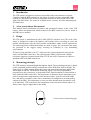
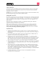
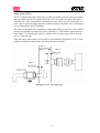
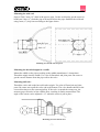
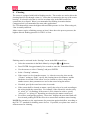
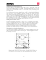
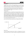
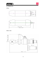
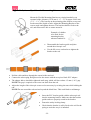
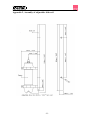
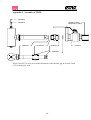
ITX and ITXIL
Suspended Solids
Sensor
2009-03-05
C2021A5EN10
TABLE OF CONTENTS
1.
2.
3.
4.
5.
6.
Introduction.......................................................................................................................... 3
A few words about this manual.......................................................................................... 3
Design................................................................................................................................... 3
Measuring principle............................................................................................................. 3
Unpacking the Sensor......................................................................................................... 4
Mounting............................................................................................................................... 5
Cable Connections............................................................................................. 5
Submersible sensor ITX .................................................................................... 5
Installation Tips ................................................................................................. 5
Inline sensor ITX IL .......................................................................................... 6
7.
Removing the sensor .......................................................................................................... 9
Removing the submersible sensor ITX ............................................................. 9
Removing the Inline sensor ITX IL .................................................................. 9
8.
Cleaning.............................................................................................................................. 10
Flushing Nozzle on submersible sensors......................................................... 11
Flushing Nozzle on inline sensors................................................................... 11
Mounting plate for cleaning solenoid valves................................................... 11
9. Menu for ITX sensor .......................................................................................................... 12
10. Calibration .......................................................................................................................... 14
Calibration points ............................................................................................ 14
Negative values ............................................................................................... 14
Calibration screen............................................................................................ 15
Automatic adjustment of the calibration ......................................................... 16
Getting good measurement.............................................................................. 16
Zero Calibration .............................................................................................. 17
Calibration with samples ................................................................................. 17
11. Scaling ................................................................................................................................ 18
12. Sensor display ................................................................................................................... 18
13. Technical description........................................................................................................ 19
ITX 20 ............................................................................................................. 19
ITX IL 15/34 ................................................................................................... 19
14. Dimensions ........................................................................................................................ 21
ITX 20 ............................................................................................................. 21
ITX IL 15/34 ................................................................................................... 21
Appendix 1, Assembly of handrail mounting kit.................................................................... 22
Appendix 2, Assembly of adjustable slide rail ....................................................................... 23
Appendix 3, Assembly of ITXIL................................................................................................ 24
Appendix 4, Support information ............................................................................................ 25
Appendix 5, Setup information ................................................................................................ 27
-2-
1. Introduction
The ITX sensor is designed to measure suspended solids concentrations in liquids.
Combined with the BB2 control box, the sensor is used to measure suspended solids
content as a function of the ability of suspended materials to absorb and reflect NIRlight (Near Infra-Red). The sensor is available in two versions; for inline mounting and
for submersion.
2. A few words about this manual
This manual details installation procedures and operational features of the Cerlic ITX
sensors. Menu navigation and technical data for the BB2 control box can be found in
the BB2 service manual.
3. Design
The ITX sensor is manufactured with 316SS (SS2343) stainless steel. The head of the
sensor is designed to achieve the highest self-cleaning effect, providing an exact and
reliable measurement with the least possible maintenance under critical applications.
The measuring lenses within the housing are made of glass. The electronics and optics
are protected in the rugged casing, ensuring its reliability in very demanding
environments.
ITX has a fixed, shielded 10 m (33”) cable used for signal transmission between the
sensor and the BB2 control box. The cable sheath is made of Hytrel and is highly
resistant to aggressive materials and fluids. ITX IL has a M12 connector to connect a
standard cable to the BB2 control box.
4. Measuring principle
The ITX measures transmitted light through the liquid. The measuring principle is based
on the suspended particles ability to absorb and reflect NIR (Near Infra-red) light. The
light source is a light emitting diode that pulses and emits monochromatic light with a
wavelength of 880 nm. The detected measuring signal is inversely logarithmical
proportional to the consistency or suspended solids. Signal treatment or linearization is
done within the BB2 control box. The temperature is measured by the transmitter to be
used for temperature compensation of the measured value. It can be read in the BB2
box, and used as secondary value when a transmitter id configured to use both analog
outputs of the BB2. The temperature is not a precision measurement, but shall be seen
as an indication. ITX 20 measures the temperature on the electronics board where it is
always some degrees higher than in the media.
Cross-section of measuring gap.
-3-
5. Unpacking the Sensor
The unit has been tested and approved before delivery from the supplier. Please check
to confirm that no visible damages occurred during shipment.
Damages
If damages occurred during shipment, immediately contact UPS or other truck line as
well as your Cerlic representative. The shipment can be returned only after contact has
been made with Cerlic.
Packaging
The original packaging is designed to protect the equipment and should be used for
storage or if the goods must be returned.
Content
Please check that the content corresponds to your order and packing list. Every
shipment should include:
Options and accessories
• Solenoid valve for flushing
Incoming hose ∅16mm (5/8”) , to sensor ∅ 6mm (1/4”)
• Aluminum mounting plate predrilled for BB2
US version
and solenoid valves w/ u-bolts,
outside US version
• 10m extension cable with plug-in connectors.
• Y-Splitter for two sensors to one BB2 control box
• Connection box for two sensors to one BB2 control box
with 1m (3 ft) cable to connect to BB2
• Connection box for four sensors to one BB2 control box
with 1m cable to connect to BB2
Optional parts for ITX Submersion sensor:
• Mounting bracket X, incl. rod holder
• Telescopic rod, 4 m, incl. transmitter holder
• Adjustable slide rail
Optional parts for ITX Inline sensor:
• Connection valve ITXIL excl. nipple
• Weld end nipple
• 1 1/2" NTP nipple
• Sealing kit
Flush membrane
O-ring between valve and adapter 48 x 2 EP70
O-ring in the adapter 33.3 x 2.4 EP70
O-ring on ITXIL 29 x 2.5 EP70
-4-
P/N
1705516
31204054
10605532
20805510
21505534
11505748
11505785
11205539
20205501
11205600
11205631
10305675
20305158
10605708
6. Mounting
Cable Connections
Connect the sensor to the BB2 control box using the attached connector on the end of
the sensor cable. In the event that two sensors are to be connected to the same BB2
control box, use the Y-splitter.
NOTE! Never try to turn the connector housing to fasten or remove the connector, only
the fluted ring at the top of the connector shall be turned.
Submersible sensor ITX
The ITX is mounted on a telescopic fiberglass rod and placed in a mounting bracket that
fastens to a handrail. Please refer to Appendix 1. As an alternative way of mounting the
sensor, an adjustable slide rail holder is available; please refer to the Appendix 2 for
further details.
When the sensor is measuring in a flume, it is important to find a place where the
suspended solids concentration is representative.
Make sure the flushing nozzle is downstream from the lenses pointing against the
stream. This will avoid having the measurement disturbed by turbulence from the
nozzle. At the same time it will produce a shield around the nozzle, due to a constant
over pressure, preventing particles from getting in.
Installation Tips
•
Adjust the rod so that the sensor is at least 30 cm (12”) below the liquid surface or
the lowest water level in decant applications to prevent the sensor from coming out
of the liquid.
•
In an aeration tank, ensure that the sensor is not directly above a diffuser head. It
should be on the backside of the rolling diffuser effect.
•
Flushing may not be required if the tank is well agitated. To verify the need for
flushing, remove the sensor from the liquid after it has been in the liquid for several
days. Place the sensor in a bucket of clean water and note the concentration value.
If the value does not get close to zero, then the flush system should be utilized.
•
When installing in a clarifier, compressed air flushing is required due to no agitation
of liquid and to remove oil and grease film on lens. This is especially applicable in
primary clarifiers.
•
When using the ITX for influent applications, always install the unit after the bar
screen. If the bar screen spacing is larger than 6 mm (¼”), then a baffle or diffuser
plate should be installed in front of sensor to prevent rags from catching on the
sensor head. On influent applications, compressed air flushing is recommended due
to the oil or grease in the liquid.
•
In effluent applications a CTX type of sensor is recommended, it has better
resolution at low concentrations.
-5-
Inline sensor ITX IL
ITX IL is mounted through a ball valve to make it possible to remove the sensor under
pressure. Make sure there is at least 260 mm (10.5”) free space to remove the sensor
from the valve. The sensor shall be mounted in a place where the process pressure is at
least 1 bar. In horizontal pipes the sensor shall be mounted from the side or from below
to avoid disturbance from air bubbles.
The sensor is designed to be mounted in a right angle to the process flow. The smallest
process pipe diameter to mount the sensor is 80mm (3”). The measure gap must be at
least 5mm (¼”) from the pipe wall. If a sample outlet is used it must reach at least 20
mm (¾”) into the pipe.
Place the sensor where there is no risk for it to get damaged. When the ITX IL is used
outdoor it shall be mounted with a sun and rain protective hood.
Min 3”
Min ¼”
Min ¾”
Mounting of sensor and sample outlet
-6-
Mounting the weld end
Open a ∅ 48,5 mm (1.9”) hole in the process pipe. Cut the weld end to get the sensor at
head least 5 mm (¼”) from the pipe wall and weld it to the pipe. Stabilize the weld end
using 3mm (⅛”) strip iron according to the figure below.
Hole 1.9”
Mounting of weld end with strip iron
Mounting the threaded nipple in a saddle
Mount the saddle on the pipe according to the saddle manufacturer’s instructions.
Thread the nipple into the saddle. Use a lot of flaxen hair and joint paste. Be aware to
get the correct distance from the pipe wall to the valve.
Mounting ball valve
Thread the valve end on the but weld end or nipple. Use a lot of flaxen hair and joint
paste. Be aware not to pull the valve end to the bottom. The valve handle shall be in the
correct direction as to the current pipeline. If the valve is turned the wrong way, the
measure gap will not be in line with the flow, resulting in faulty measurement. The
angle of the sensor can be adjusted ± 15° when the sensor is put in place.
Mounting of sensor in ball valve
-7-
Mounting of sensor in ball valve
WARNING!
•
Be aware that the force may be strong when the sensor is mounted under pressure.
•
This instruction must be fulfilled in all parts to avoid accidents or personal damage.
•
If the instructions cannot be fulfilled in all parts, the transmitter should not be
mounted or dismounted under process pressure.
•
Cerlic can not be responsible for accidents caused by not following these
instructions.
The sensor is mounted in the valve using an adapter. Make sure that the o-rings in the
adapter between the sensor and the valve, and on the sensor, below the sensor nut, are
OK. Use Silicon grease or soup to grease the O-rings before mounting the adapter. If the
adapter is separated from the sensor, check and grease the O-ring inside the adapter then
push the adapter over the sensor head having the smaller thread towards the sensor
house. Finally mount the stop ring on the sensor head.
The adapter serves two purposes
A thread for the sensor nut to keep the sensor in place.
A stop for the stop ring to prevent the sensor from coming lose when the
sensor nut is loosened.
Thread the adapter into the valve, the sensor is then fixed to the valve. When the adapter
is tightened the valve can be opened, the sensor pushed in place, and the sensor nut
screwed in place. If the process pressure is high, considerable force may be needed to
push the sensor in place. Before the sensor nut is tightened the sensor must be aligned in
parallel with the process flow.
WARNING!
• Be careful so that the transmitter is located straight. If the transmitter is not
straight the transmitter can cut jam with damages on the transmitter or valve to
follow.
• If the transmitter is hard to mount and you suspect something is stuck or that the
transmitter is not mounted straight, crank out and check that everything is OK.
• The Sensor nut can release big forces. Do not ever loose the nut without holding
the sensor in place at the same time.
-8-
7. Removing the sensor
The sensor housing may not be opened except by Cerlic service personel. Opening the
sensor housing will void all warrenty.
Removing the submersible sensor ITX
The sensor is removed in the following steps:
•
Disconnect the sensor cable from the BB2 and the flushing hose from solenoid.
•
Open the clamp, and pull the rod out of the mounting bracket
•
Make sure all water inside the rod is drained.
•
Clean the sensor and rod with a brush or clean cloth. Do not use a wire brush!
•
Open the black sensor adapter.
•
Flush the inside of the rod with clean water.
•
Mount the protective cap (or a small plastic bag) on the sensor cable connector.
•
Pull the cable and flushing hose out of the rod.
•
Blow compressed air through the flushing hose to get rid of the water in the hose
and the sensor.
Removing the Inline sensor ITX IL
The sensor is removed in the following steps:
•
Loosen the sensor nut; make sure the adapter to the valve stays on the valve.
Hold the sensor in place when the nut is removed; be aware considerable force
may be needed to hold the sensor in place if the process pressure is high.
•
Let the sensor out until it rests on the stop ring in the adapter.
•
Close the valve.
•
Disconnect the sensor cable and the flushing hose from the sensor. If the check
valve inside the sensor is worn, some liquid may come out of the sensor hose.
•
Loosen the adapter from the valve; be aware there is some liquid in the valve.
•
Remove the sensor and the adapter (they stick together).
•
Clean the sensor using a soft brush or a rag. Do not use a metallic brush or sharp
tools!
-9-
8. Cleaning
The sensor is equipped with built-in flushing nozzles. The nozzles are used to direct the
cleaning liquid or air through a 6mm (¼”) hose that is connected to the top of the sensor
housing. A solenoid valve that is wired to an alarm relay in the BB2 control box
controls the air or liquid. Water is recommended for flushing in aeration basins.
Compressed air is recommended for most other applications.
For ITX submersible sensor the highest allowed flush pressure is 6 bar. When using air,
2 bar is usually sufficient.
Inline sensors require a flushing pressure at least 2 bars above the process pressure, the
highest allowed flushing pressure for ITX IL is 8 bar.
Flushing must be activated in the “Settings” menu in the BB2 control box:
•
Select the transmitter in the Main Menu by using the
•
Press ENTER for approximately five seconds to enter the Transmitter Menu.
•
Use the arrows to select “Cleaning” and press ENTER.
•
In the “Cleaning” submenu,
•
If the sensor is to be cleaned as master, i.e. it has its own relay, then set the
“Cleaner” setting to “flush”, specify the cleaning interval in minutes, and the
flush time in seconds. If the sensor is to be cleaned as a slave, along with
another sensor, these parameters are set for the sensor being the master.
•
If needed, specify the extra freeze time in seconds.
•
If the sensor shall be cleaned as master, specify the relay to be used according to
the wiring inside the control box. For example, if the solenoid is wired to relay
#1, select “#1” for flushing. If the sensor is to be cleaned as a slave, specify
“Along #1” or “Along #2” depending on what relay the master sensor uses.
•
For sensors configured as masters, “Next time” displays the next time flush will
be activated, pushing ENTER will set it to current time and those start cleaning.
or
buttons.
NOTE! Pay attention to the requirements for protection against backflow, according to
the EN 1717 standard for drinking water devices. If possible, use plant reuse water or
effluent water for cleaning.
- 10 -
Flushing Nozzle on submersible sensors
On sensors having a serial number starting with 10- or 11- the flushing nozzle and
sensor cannot be disassembled in the field. An attempt to disassemble will void the
warranty. On newer sensors the nozzle can be removed by opening the clamping screw
next to the nozzle.
If the flushing nozzle becomes plugged, it can usually be cleaned by backflushing it
with clean water. Before attempting to backflush, close the valve for the flush water
source and disconnect the sensor flushing hose from the solenoid valve. Then, place a
12mm (½”) hose over the flush nozzle and carefully open the water valve. The pressure
should clear the line of solids. If backflushing does not work initially, try cleaning the
three flushing nozzles with a needle. Try backflushing the nozzles again as described
above until clean water comes out at the solenoid valve end of the hose.
Flushing Nozzle on inline sensors
The nozzle of the Inline sensor works as a check valve to avoid having process liquid
pressed up the flushing hose. The nozzle usually doesn’t need to be cleaned. It consists
of a rubber membrane held in place by a steel bracket. The bracket is attached to the
sensor head with two screws; the screws are secured using soft thread retainer. If
flushing is not used, the nozzle can be plugged by removing the bracket and the
membrane, then fitting a spotfaced M5x8 screw with soft thread retainer in the hole.
Mounting plate for cleaning solenoid valves
To provide an easy mounting of solenoid valves for the built-in flushing nozzles Cerlic
offers a predrilled Aluminum handrail mounting plate. The Mounting plate is fixed to
the rail using two u-bolts.
Mounting plate P/N 10305533 for one or two solenoids, P/N 11705516A for
230V and P/N 11705516B for 115V. and a connection box P/N 11505748.
- 11 -
9. Menu for ITX sensor
Use
or
to select the sensor in the main display. The menu for the selected sensor
is accessed by pressing ENTER for five seconds. If the selected sensor is not active (the
text No transmitter is shown) a warning is displayed that asks you to make another
choice in order to show the sensor menu.
SETTINGS
Name of the sensor (10 characters) shown in the main display.
Tag
I-Time
Integration time or dampening - can be set up to 999 seconds
Unit
”%”, ”ppm”, ”g/l”, or ”mg/l”
Decimals
”Std” or ”Extra”. Number of decimals for the reading.
Analog
”None” , ”Out1”, ”Out2”, ”Out3”, ”Out4”, ”Out1+2”, or ”Out3+4”.
Pick which analog output(s) to be used with sensor
Second
CALIBRATE
Adjust
”Temp” or ”=Prim”. If two are chosen above, the first will always
give the primary value according to the sensors selected scale.
The second will either give the temperature scaled 0-100°C, or
the same signal as the first channel. The temperature is
additional information, not a precision measurement.
”No”, ”Store” or ”Lab”. Stores the reading of the meter when a
sample is taken, and can then automatically adjust the sample
value when the sample analyzed by lab is different to the
reading.
Take sample
No, Zero, #1, n#2, #3, #4, #5. Sensor stores current MS (light)
value in memory and you enter a lab solids value below to
complete calibration.
Con
Sample #1
Sample #2
Sample #3
Sample #4
Sample #5
Current concentration, (same as shown in the main menu)
CLEANING
Cleaner
Lab test – consistency/suspended solids value for Sample 1
Lab test – consistency/suspended solids value for Sample 2
Lab test – consistency/suspended solids value for Sample 3
Lab test – consistency/suspended solids value for Sample 4
Lab test – consistency/suspended solids value for Sample 5
Press ENTER to go to Cleaning program
”None”, ”Flush”, or ”Brush”. Do not select “Brush” since this
does not exist for this sensor (only for master)
Interval min
Length sec
Freeze sec
0-999 minutes, time between cleaning cycles (only for master)
Relay
”-”, ”#1”, ”#2”, “Along #1”, or “Along #2”. Select relay to operate
solenoid for flush cycle if this sensor is a master with its own
relay, or relay used by master if this sensor is a slave.
These are the same relays used for “Alarm relay” below
Next time
The next scheduled cleaning time. Pushing “Enter” on this line
will set the time to current time and start a cleaning cycle. This
could be used to test the “Flush” cycle. (only for master)
0-999 seconds, duration of flushing cycle (only for master)
0-999 seconds, extra freeze time of output signal after a
flushing cycle
- 12 -
SCALE/ALARM
Max
0-99.9 % or 0-99999.9 ppm, mg/l, or g/l (units selected in the
“Settings” menu), equal to 20 mA output signal.
Min
0-99.9 % or 0-99999.9 ppm, mg/l, or g/l (units selected in the
“Settings” menu), equal to 4 mA output signal.
Hi-Alarm
0-99.9 % or 0-99999.9 ppm, mg/l, or g/l (units selected in the
“Settings” menu) , the value zero inactivates the alarm
Low-Alarm
0-99.9 % or 0-99999.9 ppm, mg/l, or g/l (units selected in the
“Settings” menu) , the value zero inactivates the alarm
Alarm Relay
”-” ”#1”, ”#2”, or ”#1 and #2”. Check that the relay is not being
used for cleaning
SYSTEM
Type
Serial
SoftW
Temp
MaxTemp
Samples
SA 0
SA 1
Cons 1
….
Info
Type of sensor, read only
Serial number of the sensor, read only
Software version of the sensor, read only
Sensor temperature, read only
The highest temperature the sensor has been exposed to, read only
Press “ENTER” to go to view SA values and consistency or
suspended solids values.
SA value for zero sample
SA value for sample # 1
Lab test - consistency or suspended solids value for Sample # 1
SA and Cons repeated for samples 2 to 5
Press “ENTER” to go to “info” read only menu. This menu is for
Cerlic internal use, it may change without notice
MS
Con
SA 0
SA 1
Cons 1
Ch1a
Ch1
Ch2
Intensity
Zero Int
I-offset
Samp/s
Service
linearized light signal, which are SA values in calibration chart
Unit value in %, ppm, mg/l, or g/l after MS value has been
converted to units due to sample values. This is displayed on
main screen
SA value for zero sample
SA value for sample # 1
Lab test - consistency or suspended solids value for Sample # 1
Raw value for channel 1
Raw value for channel 1, compensated for changed intensity
Raw value for channel 2
Currently used intensity
Intensity for clear water, set during zero calibration
Intensity offset, set during zero calibration
Number of samples per second
Not accessible for users.
- 13 -
10. Calibration
The BB2 has a self-optimizing calibration algorithm/curve able to handle several
calibration points in order to give maximum measuring precision in difficult
applications. Usually however, a single point calibration is preferred. After a calibration
has been carried out, make it a habit to look at the calibration curve in the sensor
information screen to make sure it represents a smooth line without ant sharp bends.
It is important that the instrument has been turned on for about 30 minutes prior to
calibration so that the sensor and electronics can stabilize. Please check that the correct
unit (consistency/suspended solids) is selected for the application. Select unit in the
sensor menu “SETTINGS” – “UNIT”.
Calibration points
To calculate the consistency or concentration out of the loss of light the sensor uses a
calibration curve. The curve is built up of the zero calibration point and at least one
calibration point. Each point has a sample value and a consistency value. To be used a
point needs both values, the sample value is set by “take sample” in the calibration
menu, the consistency value is manually entered in the same menu after having
analyzed the actual consistency at the time the sample was taken. A calibration point
can be disabled by setting the consistency value to zero. In most applications one
calibration point in addition to the zero sample is the best solution, adding more samples
then just confuses the measurement. The only cases more than one calibration point is
useful is when the measurement turns out to be non linear, or when the sensor needs to
be very accurate at widely separated consistencies.
The zero calibration defines the zero point used as a reference for all other calibration
points. The other points define the relation between loss of light and real consistency.
Loss of light
0
Consistency
0
Negative values
The sensor contentiously compares the loss of light to its calibrated points. If, for some
reason, the loss of light is less than when the sensor was zero calibrated, the meter shows a
negative consistency. This is not a fault, it just indicates the liquid in the sensor absorbs less
- 14 -
light than the liquid used as zero reference. Please contact Cerlic service if this is a problem
for you.
Calibration screen
The ITX sensor information menu is the calibration curve screen. To change between
the main menu and the calibration screen, press
and ENTER simultaneously.
C
Multi point calibration
Single point calibration
BB2 uses at least a zero sample and one sample (single point calibration). Up to five
samples may be used to create a calibration curve (multi point calibration). The samples
are sorted internally in order of signal intensity. The sample numbers however, doesn’t
change, only the order they are used. The calibration menu displays sample values
placed in a graph.
• X-scale displays consistency/suspended solids, where min –value (4 mA output) is
shown to the left and max -value (20 mA output) is shown to the right.
• Y-scale displays the light loss due to solids from the sensor light source. BB2 uses
the light loss values to calculate which measuring signal corresponds to minconsistency/suspended solids and max-consistency/suspended solids.
• Actual measuring value is indicated with an arrow that moves up and down to the left
of the Y-scale axis.
• Samples that are not within the chosen scale of the active sensor are not displayed on
the calibration screen. However, these samples are still used in the calculations. If
you want to see a point outside the sensor scale, then you may temporarily change
the scale in the sensor menu.
If the sample values are switched or the lab result is incorrectly performed, then the
calibration curve will be incorrect. Such a mistake is easy to discover on the calibration
screen since a part of the calibration curve will go in the wrong direction. Different
measuring values should never correspond to the same consistency / suspended solids.
The curve goes backwards
because two samples have been
exchanged when entering the lab
results. Higher Y-value must
mean higher X-value. The curve
must have a direction upwards
and to the right.
Incorrect calibration!
- 15 -
Automatic adjustment of the calibration
The function ”Adjust” in the calibration menu is used to automatically adjust the
calibration in an easy way. When a sample is taken to be analyzed by lab, BB2 stores
the reading. When the sample has been analyzed, the result is keyed in to the BB2 who
will compare it to the stored reading and calculate a new setting for the sample value.
Automatic adjustment only works for single point calibrations and is primaryli intended
as an easy way to get started with a new sensor. Once the automatic adjustment is done,
and the sensor gives a sensible reading, we recommend using a statistical adjustment to
get a higher accuracy over time, se below.
Running an automatic adjustment:
Fill a bucket with a sample of the liquid you intend to measure. Submerge the sensor
into the liquid. Even though the sensors have daylight-filters they are sensitive to the
infrared parts of the sunlight. Always cover the sensor and the bucket before calibration.
Select the sensor to be calibrated in the menu by using
or
arrows
Press ENTER for approximately five seconds to enter the sensor menu.
Use
and
arrows to select “Calibrate” and select “Adjust”, and then “Store”.
Select “Take sample” and stir the sample in the bucket until the measuring is finished.
•
Replace the rod/sensor in the SS mounting bracket so the sensor is at least 12”
(36 cm) below the lowest liquid level in the basin. Take the bucket to the lab for
analysis. Note the concentration of the sample determined at the lab.
Use
and
ENTER.
arrows to select “Calibrate” and select “Adjust”, and then “Lab”. Press
Press ENTER to use the stored reading , or
to key in a value.
Key in the result of the lab analyze, then press ENTER.
BB2 will show current and suggested new value for ”Sample 1”, acknowledge the
or .
change by pressing ENTER or abort using
Getting good measurement
Statistic adjustment of the lab sample value is a much better way to good measurement
than frequent calibration. This is done comparing the lab results with the instrument
reading over time. If a systematic discrepancy is detected, the value of the lab sample
used in BB2 is changed accordingly. If for example several lab results for a period of
time in average shows 5% more than the instrument, the sample value in BB2 shall be
increased 5% of its value, e.g. if the sample value is 10000 mg/l it shall be changed to
10500. Using statistic method will increase the accuracy and reliability of the
measurement as time passes while new calibrations will start from scratch. An Excel
sheet to help doing statistical adjustment of the calibration can be downloaded from
http://www.cerlic.com
- 16 -
Zero Calibration
The sensor is zero calibrated at the factory, and does not often need to be zero
calibrated. Before doing a zero calibration, always check that it is really needed. Make
sure the lenses are clean, and use clean de-aerated water to check the meter reading.
Cover the bucket to avoid direct sun light. Tap water is best de-aerated by leaving the
water in an open bucket for at least two hours.
Running a zero calibration:
Remove the sensor from the process, clean the sensor head, and dip it in a bucket of
clean water. Even though the sensors have daylight-filters they are sensitive to the
infrared parts of the sunlight. Always cover the sensor and the bucket before calibration.
Select the sensor to be calibrated in the menu by using
or
arrows
Press ENTER for approximately five seconds to enter the sensor menu.
Select “Calibrate” and select “Take sample”. Press ENTER.
•
Select “Zero” and press ENTER.
•
To acknowledge that you really want to change the zero calibration, select “Yes”
and then press ENTER.
•
BB2 will ask you to put the sensor in clean water. Submerge the sensor head into
the clean water and cover it from direct sunlight, then press ENTER.
•
Wait for the zero calibration to finish. It will take approximately thirty seconds
before the unit returns to the menu.
Detailed procedures for navigating the BB2 software can be found in the BB2 service
manual.
Calibration with samples
Calibration with sample in a bucket
Fill a bucket with a sample of the liquid you intend to measure. Submerge the sensor
into the liquid. Even though the sensors have daylight-filters they are sensitive to the
infrared parts of the sunlight. Always cover the sensor and the bucket before calibration.
•
Select the sensor to be calibrated in the menu by using
•
Press ENTER for approximately five seconds to enter the sensor menu.
•
Select “Calibrate”
•
Select “Take sample”. and select “#1”
•
Press ENTER and stir the sample in the bucket until the calibration is finished. It
will take approximately thirty seconds.
•
Replace the rod/sensor in the SS mounting bracket so the sensor is at least 12”
(36 cm) below the lowest liquid level in the basin. Take the bucket to the lab for
analysis. Note the concentration of the sample determined at the lab.
•
Enter sample #1 concentration by going to Sample #1 in the calibration menu
and pressing ENTER. Use the arrows to change the values and ENTER to go to
the next digit.
- 17 -
or
arrows
•
Some special applications may nead additional sample points. Do not enter
samples that are identical in concentration or less than 10% from initial values.
Calibration of submersible sensor in a basin or channel
Calibration can be done without the use of a bucket. Make sure that the sensor is at least
30 cm below the lowest liquid level. Follow the above procedure, while the ITX is
calibrating, grab a sample of the liquid with a dip bucket to take to the lab for analysis.
Make sure to grab a sufficiently large sample volume for low solids applications.
Calibration of Inline sensor in a pipe
Inline sensors are easiest calibrated if the pipe has a sample outlet. Follow the above
procedure, while ITX IL is calibrating, open the sample valve and fill a bucket with
process liquid. Take the bucket to the lab for analysis. Note the concentration of the
sample determined at the lab.
11. Scaling
The “Scale / Alarm” menu (see the BB2 manual) allows the user to set the high and low
boundaries for a 4-20mA output signal. In addition, this menu allows the user to set
high and low alarm values to energize a relay when solids have reached critical points.
Max
sets the 20 mA point output
Min
sets the 4 mA point output (may be negative for special applications)
Hi-Alarm
sets the High Alarm set point, the value zero inactivates the alarm
Low-Alarm sets the Low Alarm set point, the value zero inactivates the alarm
12. Sensor display
By simultaneously pressing
and ENTER you alter between BB2 main menu and the
sensor information display for the selected sensor. ITX has a information display, it
shows the sensor’s calibration curve.
- 18 -
13. Technical description
ITX 20
P/N
11305455
Material
316SS (SIS2343)
Dimensions
See section 14.
Weight
1,6 kg (3,5 lbs)
Process connection
Submerged
Max Depth
10 m (33 ft)
Max temperature
60°C (140°F)
Measuring principle
Measuring range Min
Max
Straight transmission, 20 mm measuring line
0-100 mg/l
0 – 20000 mg/l (application dependent)
Cable, connection
5-pin M12-plug
Cable, length
10 m (33 ft)
Cable, material
Flushing
Hytrel
Clean water or instrumentation air.
Flushing, Pressure
max 6 bar (90 psi)
Flushing hose, length
10 m (33 ft)
Flushing hose, material
PE-LD
Enclosure
IP68 NEMA 4X
ITX IL 15/34
P/N
Material
11305630
SIS2343 (316SS)
Dimensions
Weight Sensor
Valve
Process connection
Max process pressure
See section 14.
2,4 kg (5.25 lbs)
2,2 kg (4.8 lbs)
Inline sensor, 1½” ball valve
6 bar (90 psi) (10 bar (150 psi) with plugged flushing
nozzle)
Max process temperature
60°C (140°F)
Measuring principle
Measuring range Min
Max
Straight transmission, 15 mm measuring line
0-100 mg/l
0 – 5 % TS (application dependent)
Cable, connection
Flushing
Flushing, Pressure
Enclosure
5-pin M12-plug
Clean water or instrumentation air.
2 bar (30 psi) above process pressure, max 8 bar (120 psi).
IP65 NEMA 4
- 19 -
Certificate of conformity:
The ITX sensors along with their central unit BB2 are in conformance with the
following EC Directive(s) when installed in accordance with the installation instructions
contained in the product documentation:
73/23/EEC
Low Voltage Directive as amended by 93/68/EEC
89/336/EEC
EMC Directive as amended by 92/31/EEC and 93/68/EEC
The following standards and/or technical specifications have been applied:
EN 61000-6-4:2001
Electromagnetic compatibility (EMC) Part 6-4
Generic standards – Emission standard for industrial
environments
EN 61000-6-2:2001
Electromagnetic compatibility (EMC) Part 6-2
Generic standards - Immunity for industrial environments
EN 61010-1:2001
Safety requirements for electrical equipment for measurement,
control, and laboratory use
- 20 -
14. Dimensions
ITX 20
ITX IL 15/34
- 21 -
Appendix 1, Assembly of handrail mounting kit
Mount the Flexible Mounting Bracket on existing handrail or on
separate holder, diameter 32-50 mm (1 ¼” – 2”) or square 28-42 mm
(1 ⅛” – 1 ⅝”). The bent lip on the mounting plate shall be on top and
faced toward the liquid or tank. Adjust the Mounting Bracket to the
correct angle and tighten the nuts. The bracket shall be fixed to the
rail, and must not be able to rotate around it.
Example of a holder
to be used for the
mounting bracket
when no handrail is
•
Disassemble the bracket guide and place
around the telescopic rod.
•
Use the SS screws on bracket to tighten the
bracket to the rod.
•
Pull the cable and hose through the sensor holder and rod.
•
Connect the telescoping fiberglass rod to the sensor with the two piece black PVC adapter.
•
The adapter halves should be tightened until snug, which will leave about 1.5 mm (1/16”) gap.
NOTE! The gap is required so the water can drain from the rod.
•
Adjust the length of the telescopic sensor rod as necessary by twisting the nuts while holding the
rod.
NOTE! Do not extend the rod sections beyond the black lines. This could lead to rod damage.
•
Insert the PVC bracket guide with the telescopic rod
into the mounting bracket. Make sure that the bracket
guide tracks are properly seated in the bracket.
•
Fasten the safety-locking clamp.
•
Check that the bracket is safely fixed to the rail for the
spring to work the way it is intended.
- 22 -
Appendix 2, Assembly of adjustable slide rail
- 23 -
Appendix 3, Assembly of ITXIL
20250222
10305675 (weld)
20305158 (1½”NPT)
20250679
21650570
21650575
21650574
11205631
10305639
Nipple 10305675 is to be cut to make the bottom of the measure gap be at least 5 mm
(¼”) from the pipe wall.
- 24 -
Appendix 4, Support information
Before calling Cerlic Support, please collect the information in this form and have it at
hand.
Company
_____________________________________________________
Name
_____________________________________________________
Phone
_____________________________________________________
E-mail
_____________________________________________________
Sensor Type
_____________________________________________________
Position / Tag _____________________________________________________
First go to the BB2 menu, it is accessed by pressing
five seconds. Select “System” and press.
and ENTER at the same time for
Version
_____________________________________________________
Serial
_____________________________________________________
Box temp
_____________________________________________________
Leave the BB2 menu by pressing
and ENTER at the same time. Use
or
to
select the sensor in the main display. Go to the sensor menu, it is accessed by pressing
ENTER for five seconds. Select “System” and press ENTER.
Type
_____________________________________________________
Serial
_____________________________________________________
SoftW
_____________________________________________________
Temp
_____________________________________________________
Select “Samples”, then press “ENTER” to go to the “Samples” sub menu.
SA 0
_____________________________________________________
SA 1
_____________________________________________________
Cons 1
_____________________________________________________
SA 2
_____________________________________________________
Cons 2
_____________________________________________________
SA 3
_____________________________________________________
Cons 3
_____________________________________________________
SA 4
_____________________________________________________
Cons 4
_____________________________________________________
SA 5
_____________________________________________________
Cons 5
_____________________________________________________
- 25 -
Return to the “System” menu. Select “Info”, then press “ENTER” to go to the “info”
menu.
MS
_____________________________________________________
Con
_____________________________________________________
SA0
_____________________________________________________
SA1
_____________________________________________________
Cons 1
_____________________________________________________
Ch1a
_____________________________________________________
Ch1
_____________________________________________________
Intensity
_____________________________________________________
Zero Int
_____________________________________________________
I-offset
_____________________________________________________
Leave the BB2 menu by pressing
and ENTER at the same time.
- 26 -
Appendix 5, Setup information
This sheet can be used to document the setup of a sensor.
Sensor Type
_____________________________________________________
Position / Tag
_____________________________________________________
In the System sub menu of the sensor menu the following information can be collected.
Serial
_____________________________________________________
SoftW
_____________________________________________________
In the Settings sub menu of the sensor menu the following parameters can be set.
I-time
_____________________________________________________
Unit
_____________________________________________________
Analog
_____________________________________________________
Second
_____________________________________________________
In the Cleaning sub menu of the sensor menu the following parameters can be set.
_____________________________________________________
Cleaner
Cleaning interval _____________________________________________________
Cleaning length
_____________________________________________________
Cleaning relay
_____________________________________________________
In the Scale / Alarm sub menu of the sensor menu the following parameters can be set.
Max
_____________________________________________________
Min
_____________________________________________________
High alarm
_____________________________________________________
Low alarm
_____________________________________________________
Alarm Relay
_____________________________________________________
Leave the BB2 menu by pressing
and ENTER at the same time.
Cerlic Controls AB, P.O. Box 5084, SE-141 05 Huddinge
Tel: +46 8 501 694 00, Fax: +46 8 501 694 29, [email protected] www.cerlic.com
- 27 -