1
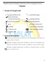
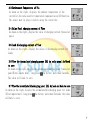
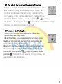
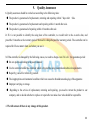
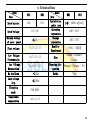
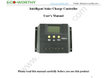
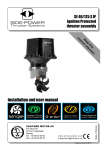
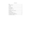
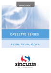
60I/80I Intelligent Solar Charge Controller
User's Manual
1
Catalogue
1. Product Introduction..............................................2
2. Installation..............................................................3
3. Operation................................................................4
4. Common Fault and Handling...............................9
5. Quality Assurance.................................................10
6.Technical Data........................................................11
2
1. Product Introduction
I series controller is a kind of intelligent,multi-purpose solar charge and
discharge controller. The family use the fixed LCD display, with a very friendly
interface; various control parameters can be flexibly set, fully meet you’re your
various application requirements.
I series controller has following features:
● Image of LCD graphic symbol
● Simple button operation
● Automatic Identification System Voltage level
● Intelligent PWM charge mode
● Automatic Temperature Compensation
● Adjustable charge-discharge control parameters
● Settable Operating mode of Load
● Overload, Short Circuit Protection
● Remote monitoring and control function (custom)
● Battery reverse-discharge protection
● Battery Low Voltage Disconnection (LVD)
● Battery reverse connection protection
● Accumulated function of charge and discharge Ampere hours
3
2. Installation
Install:
① Ready tools and cables. Encourage you to matching
the right cables. Ensure that the current density<4mm2
that is conductive to reducing the line voltage drop.
Recommended: 60A with 20mm2 cable.
Check weather the installation sites compliance with
the relevant safety requirements. Please avoid the
damp, dusty, there is a place flammable, explosive and
corrosive gases use the controller to install.
Temperature
Sensor Port
② Install the controller into a fixed vertical plane. See
Solar Panel
section 5 of the pore size and pore spacing. In order
to ensure a good thermal control conditions, please
set aside each 10cm below the controller space.
Solar Charge
Controller
Remote
monitoring
and control
port
FAUSE DC Load
Battery
③ As shown on the right, connect the (1) Load,
(2) Battery and (3) Solar Panel to the controller according to the order of (1) (2) (3). Pay attention
to the load, battery, solar panel and controller of same polarity.
④ Put into the external temperature sensor on the left of the controller (probe port). The temperature
sensor should be similar space with battery. (Otherwise, the controller will control the parameters of
all wrong temperature compensation.)
⑤ If you have remote monitoring and control function, please insert one end of the included
communication wire on the right of the controller (communication port), the other end to connect to
The host computer.
Demolition: To prevent accidents, please order the demolition of solar panels, battery and load disconnect with
controller.
4
Note:Battery polarity will not damage the controller, but you will have a load equipment security risks.
3. Operation
1
2
Description of LCD graphic symbol
:Stop-powered Status for Loads
:Power to the load status,
the load circuit without current
:The load circuit with current
:Stop the battery charging
:Bulk charging the battery
:Float charging the battery
:Load
:The system is working correctly
:Solar Panel
:The system is not working properly
:Load sensor control
:Battery charge capacity instruction
:Load timer control
:Battery
Description of Button Function:
:Interface loop switch button, use the button to cycle between pages in each switch cycle
sequence shown in (figure 1)
:Adjustment of parameters plus buttons. In addition, at the state in the parameter view,
long press the button more than 5 seconds, all parameter to restore factory setting.
:Adjustment of parameters minus button. In addition, in the main interface, click this
button to switch the load.
5
Battery Voltage
(main interface)
Battery
temperature
Solar Panel
charge current
Accumulated
Accumulated
Load
Discharging power(Ah) charging power(Ah) discharge current
Figure 1
3
View
the parameters
The controller will default entry “battery voltage” interface after correct power-on. This
is them ain interface. Use the button
could in turn visit the following parameters
interface
3.1 Battery Voltage of View
As shown on the right, displays the value for current battery voltage.
This interface (based interface) displays charge status, discharge
status,battery capacity and battery voltage.
3.2 The load on/off control
View the interface in the battery voltage could be
used key
On, off the load. In other interface,
The key there is no such feature.
6
3.3 Environment Temperature of Vie
As shown on the right, displays the ambient temperature of the
controller,the value used for temperature compensation on LVD function.
The sensor must be plug in before using the controller.
3.4 Solar Panel charging current of View
As shown on the right, display the value of charging current from solar
panel.
3.5 Load discharging current of View
As shown on the right, display the value of discharging current for
Loads.
3.6 View the Accumulated charging power (Ah) by solar panel And back
to zero
As shown on the right, display the accumulated charging power from solar
panel(Total ampere hour), long press
the button more than 5seconds,
The value will back to zero.
3.7 View the Accumulated discharging power (Ah) by Load and Back to zero
As shown on the right, display the accumulated discharging power for loads
(Total ampere hour), long press
the button more than 5seconds, the value
willback to zero.
7
4
Set the parameters
At the main interface press
for long (>5 seconds, and the number starts flickering) to enter into parameter
Setting interface. Press
for short ( < 1 second) to reset the parameter, and press
,
to adjust this
parameter.
High Voltage
Low voltage
Disconnection (HVD)
Reconnection (LVR)
Figure 2
Load
main interface
Low voltage
Working Mode
Disconnection (LVD)
4.1 Set the High Voltage Disconnection
As shown on the right, shows the values for the HVD voltage.When
the battery voltageis reach to HVD voltage, the controller will
cut off the charging circuit to prevent over-charging battery.
Battery voltage drops under the value the charging circuit will
be re-connected.In this interface,numbers start flashing, you can
use the key
,
to adjust the parameter. After long press the key
(>
5seconds)to exit parameters etting interface, the controller will save the settings.
4.2 Set the Low Voltage Reconnection
As shown on the right, shows the values for the LVR voltage. Under the LVR
protection in the controller, when the battery voltage is restored to the higher voltage
than LVR voltage, the controller will re-connect the load circuit. In this interface,
numbers start flashing.You can use the key
the parameter. After long press
,
the key (>5seconds)to exit parameter setting Interface, The controller will save the settings.
8
4.3 View and set the Low Voltage Disconnection Protection
As shown on the right,shows the values for the LVD protection voltage.
When the battery voltage is lower than protection voltage, the
controller will disconnect the load circuit to prevent battery
over-discharge.In this interface,numbers start flashing,that has
entered the LVD setup interface, you can use the key
、 to adjust
the parameter. After long press the key (>5seconds)to exit parameter setting
interface, the controller will save the settings
4.4 View and set Load Working Mode
As shown on the right is Load working mode interface, different values
represent different load working patterns.
24h said Normal Mode, in case of no fault state of the load is always in power.
1h~23h said Light Control with Time Control Mode, Load power after dark,
and close the load according to the timer setting.
0h said Light Control Mode, Load power after dark, turn off the load after drawn.
In this interface,numbers start flashing, that has entered the Load Working Mode
setup interface, you can use the key
,
to adjust the parameter. After long
press the key
(>5seconds)to exit parameter setting interface, the
controller will save the settings.
9
4.Common Fault and Handling
LVD Protection and Treatment
Screen display as shown in the figure that the battery drops below the LVD
protection voltage. The controller has entered the LCD protection state, load circuit
has been disconnected. Use the solar panels recharge the battery or charger when
the battery voltage reaches LVR voltage, the controller will resume on the load
power supply, into the normal working state.
Over load Protection and Treatment
Screen display (see the figure) and flashing expressed load loop circuit current
sustained 60seconds than 1.5times rated current, the controller has entered into
overload protection state. After reduce the load, press the button
to restore
power to the load.
Short Circuit Protection and Treatment
Screen display (see the figure on the right) and flashing expressed there is short
circuit on the load loop circuit. The controller has enter into Short Circuit Protection
state Check the load if there is damage or not, if there is cable short circuit or not,
after trouble shooting short press
the buttonfor restoration.
Solar Panel Fault and Treatment
Symbol flashing represent the controller was not detected solar panels within 24hours. Check if
there is a connection from solar panel, check if there is an open circuit between solar panels with
controller.
Load Shock Fault
Open load if the
flashing, that indicate the load impulse current is more than twice rated current of
the controller. The controller is restarting the load in action many timers do.
10
5.
Quality Assurance
1. Quality assurance should be carried out according to the following rules:
● The product is guaranteed of replacement, returning and repairing within 7 days after
Sale.
● The product is guaranteed of replacement and repairing within 1 month after sale.
● The product is guaranteed of repairing within 12 months after sale.
2. If it is not possible to identify the using date of the controller, we would refer to the ex-work date, and
prescribe 18 months as the warranty period. We need to charge beyond the warranty period. The controller can be
repaired for life no matter when and where you use it.
3. If the controller is damaged by the following causes, we need to charge even if it is In the guarantee period:
● Do not operate according to the user's manual.
● Use the controller under the condition which is beyond the using standard and technical requirements.
● Repair by yourself or reform by yourself.
● The inappropriate environmental condition which can cause the breakdown and aging of the apparatus.
● Improper carrying or storage.
● Regarding to the service of replacement, returning and repairing, you need to retreat the product to our
company, and we decide whether to replace or repair after we make clear who should be responsible.
4. We will not note if there is any change of this product.
11
6. Technical Data
Model
Data
Rated current
60I
80I
60A
80A
Model
Data
Installation
cable area
Operating
temperature
Storage
temperature
Humidity
Requirement
60I
80I
>3# AWG (<25mm2)
-20℃~50℃
Rated voltage
12V/24V
Maximum voltage
of solar panel
≤50V
Float voltage
13.7V/27.4V
Low Voltage
Disconnection
10.7V/21.4V
Size
130mm×188mm×
62mm
Low Voltage
Reconnection
12.6V/25.2V
Mounting hole
spacing
98 mm×178 mm --Φ5
Weight
700g
No load loss
<30mA
Loop voltage
drop
≤200mV
Charging
mode
PWM MODE
Temperature
compensation
-4mV/Cell/℃
-30℃~70℃
≤90%, 无凝露
12