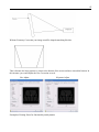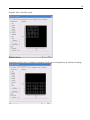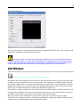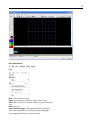
1
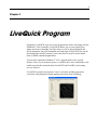
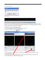
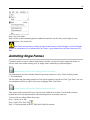
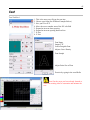
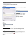
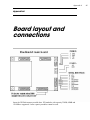
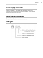
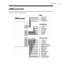
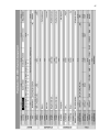
Pangolin Laser Systems LiveQUICK Flashback 3 SE for October 2007 Due to our policy of continuous product improvement, information in this manual is subject to change without notice. November 2008 Contents 1: Introduction In this package Functions 4 5 2: Installing CD-ROM contents XD/Smartmedia contents Notes about memory utilization USB driver installation Installing LiveQuick software 6 7 7 7 7 3: LiveQuick Program Introduction Getting started Menu structure Shortcuts Page tabs Live control and info tabs Projector settings Projection zones Edit window Shortcuts Color 9 9 13 15 15 15 19 20 24 28 29 Frame file list Creating content Drawing Tracing 30 30 34 37 Animating single frames Text Cue properties Linking Troubleshooting Log files 39 40 41 44 45 45 4: DMX and Standalone Standalone mode DMX-512 46 46 Appendix A: Board layout and connections Power supply connector Serial interface connector USB Lights DMX connector Expansion connector Projector connector 49 49 49 50 51 51 DMX channel assignment 51 Chapter 1 Introduction The Flashback 3 is the smallest, easiest and most economical way to add high-quality graphics and beams to a stand-alone laser projector. In fact, the Flashback 3 is so impressive, that it won the ILDA Hardware Product Of The Year Award in 2006. This credit-card sized wonder can play laser graphics, beams and even complete Pangolin-quality shows. No extra computer hardware is needed – the tiny Flashback 3 has everything you need to control your laser projector. The Flashback3-SE is the latest addition to this product line. In this package Included in this package you will find a CD-ROM, and the Flashback 3-SE, which is the combination of Flashback 3 base board, a USB daughterboard, and a XD memory module, preloaded with some example content. Though, the basic functionality can be achieved with only using Flashback 3 Base Board, additional functionality is manifested with the addition of daughter boards. This “daughter board” approach allows Pangolin to produce semi-custom products to suit the needs of individual OEMs, thus allowing you maximum integration flexibility and also allowing you to differentiate your products in the marketplace. Pangolin can easily create customized daughter boards as needed by OEMs. Please contact us with your specific function requests. Chapter 1 Introduction 5 Functions The FlashBack 3 Base Board contains the following basic functions: • USB power supply. • XD socket with ability to accommodate modules from 32MB to 128MB • 12-bit X and Y outputs with single-ended voltage level of +/-5V • 8-bit Red, Green, Blue and Intensity outputs with single-ended voltage level of 0 to +5V • TTL-level Shutter/Utility signal (internal) The USB daughterboard adds the following functionality to Flashback 3: • High speed connection between Flashback 3-SE and PC (480 Mb/s) • LiveQuick – a PC application for full control of Flashback 3-SE, which allows: • uploading the content to XD card • creation and editing frames and animations • live total control of the Flashback 3-SE • updating the Flashback and DMX daughter board firmware changing the settings for Flashback 3-SE standalone operation. The DMX daughterboard adds the following functionality to Flashback 3: • DMX-512 control – allows using an industry standard control protocol • Real time geometry manipulation – size, position, rotation control Chapter 2 Installing To use the Flashback 3-SE, you will need to connect the supplied USB cable to one USB port available on your computer. For standalone operation, a USB A/C adapter (charger) can be use to power the unit. You will also need to connect the DB25 to a projector. The DB25 connector is connected as a QM2000/ILDA-compatible connector. CD-ROM contents The CD-ROM included with this package includes: • the LiveQuick program, • the workspace file that was uploaded to a XD module, • the USB drivers for Flashback 3-SE • Tutorial videos (Cypher) • LAStudio: TraceIt • LAStudio: ShowRider • LAStudio: Draw 3D • LAStudio: Abstraction 7 XD card contents A XD memory module is included with this evaluation package, and is programmed with the following example content: Zone 1 Graphic effects Zone 2 Atmospheric effects Zone 3 Target Beams Zone 4 User defined The content included should work well for Cambridge scanners tuned to 30K. Lower-performance scanners can be accommodated by slowing down the default scan rate in Projector settings (Tools menu). Notes about memory utilization This evaluation kit includes a 128MB module which can contain around 20 minutes worth of frames and animations. The FlashBack 3-SE will work with XD module with capacity from 32MB to 128MB. The data format used by the FlashBack 3 includes a compression scheme, which is why we are able to get such good memory utilization. Currently, data is stored for red, green and blue color outputs. For applications requiring better memory utilization but with only a single color, the animation capacity can be doubled. Contact Pangolin if you have such a need. USB driver installation When you connect the Flashback 3-SE to USB port of your computer, the ‘New Hardware’ wizard will appear. You should not use automatic install procedure. Instead, you should point the wizard to the USB driver directory on the Evaluation Package CD-Rom. Installing the LiveQuick software LiveQuick should begin installation when the CD is inserted, or click in install.exe. To manually install the Livequick software application, simply copy the LiveQuick folder from the CD ROM to your computer. Copy the folder Workspaces to the same folder you moved LiveQuick to evaluate the included workspace on the memory card of the Flashback3. If you do not move the folder Workspaces to your computer, LiveQuick will create a blank Workspaces folder. 8 Chapter 3 LiveQuick Program Pangolin's LiveQUICK is an easy-to-use program that can be used along with the Flashback 3 Laser Controller. LiveQUICK allows you to create simple laser frames and scenes, including TrueType fonts, as well as import Pangolin and ILDA animations. Once the animations are loaded into LiveQUICK, they can be downloaded into the FB3 memory card so that the FB3 may be used in standalone or DMX-controlled applications. You can also control the Flashback 3 "Live" using the built-in live control features. Later, if you need more power, LivePRO can be used. And thanks to the similar user interface shared by both LiveQUICK and LivePRO, the learning curve is reduced. LiveQUICK provides four separate "zones" of control, including geometric correction, using Pangolin's patent-pending Projection Zone technology. 9 Introduction The LiveQuick Program allows you to: • Trigger cues by clicking on buttons with the mouse, • Upload frames or complete animations to the Flashback 3 board, • Create and edit the frames and animations on line (real time editing), • Live control of several parameters during cue playback, • Update the firmware on Flashback 3 Base Board and DMX Daughter Board, • Change the settings to be used in standalone mode (autostart). Refer the provided video training course for practical lessons on using LiveQuick Software and discover the unique power and simplicity of LiveQuick. Getting Started 1. Opening a. From the drop down menu (FILE) select Open Workspace b. Select the workspace in the workspace folder and click open 10 c. Your workspace file will load and you will then see cues (Laser content) in the cue windows. Note: The workspace file may load automatically if you copied a workspace file into the workspace folder prior to launching the program. d. Your Screen should show cues with content in them like this: e. Connection Status: When your device is connected to the PC properly the software will automatically check the connection and then tell you if there are any differences between what is on the memory card and what your current workspace data is showing. f. If there is a difference between your workspace and the information located on the memory card and this is your first connection to the PC to your device this is perfectly normal. Follow the prompts as such g. Warning message: Firmware i. The firmware on the memory card is different from the firmware for this version of software. Do you want to update the firmware? ii. Click Yes: The system will automatically update the firmware for the devices that are embedded in your projector or control system. h. Warning message: The memory card format needs to be reformatted. Do you want to reformat? i. Click Yes: The software will format the memory and scan the memory blocks. If the system finishes this process and tells you that there are some unusable memory blocks this is normal. i. You will notice at this point that in each cue cell that there is a memory card icon in the upper right hand corner. This means that the workspace needs to be re-uploaded to the memory card. But don’t do that just yet. Proceed to section 2 to familiarize you with the Graphical User Interface. Some of the settings adjustments you will do there will cause the memory to be uploaded again. It is better to finish the set up and make all desired changes prior to uploading. 11 2. Firmware and Hardware Relationship The control system within your projector or control device such as LiveQuick Pro Remote is a sophisticated communication system. Internal to your device is a control PCB and hardware PCB’s that all have to communicate with each other properly to function well. This balance is put in place and ensured via the integrated firmware updating system within the software. Additionally depending on what hardware is present certain aspects of the GUI (Section 3) will be or not be present. The hardware inside your device communicates with the motherboard via a internal Ethernet. We call these PCB’s that are not a part of the mother board (Daughter Boards) In the information Tab (Section 3.2) within the LiveQuick Software you can see exactly what hardware you have in your device. These will read, FB3, USB, DMX, UI (User Interface), BT1, (Beam Table 1), and (BT2 Beam Table2) When you connect your device to communicate with the hardware and can tell exactly what hardware is embedded in your device as well as the firmware version on each PCB. If the firmware does not match the requirements to communicate with your version of software it will prompt you to update the firmware. If the firmware on your device does not match with the version of software provided with your device you will be prompted to update the firmware. This is normal… Select OK. After the firmware updates you may be prompted to format the memory card. This is normal… Select OK. (If you see that there are some unusable memory bocks this is normal as well. Disregard) Is your device connected? There are several ways to check this but the main ones are: a. Lower left hand corner of the (GUI) software screen Offline (Not Connected) [Edit] Online (Connected) b. Information Tab 12 c. Windows Device Manager 3. Graphical User Interface (GUI) See the Factory CD for a video Training Course on this topic The Graphical User Interface (GUI) of LiveQuick is a very simple GUI and is organized in such a way that it is logical to all modes of device operation such as DMX 512, USB, Auto Play, and Sound Active. In this section each aspect of the GUI will be explained and then frther on in the manual the key elements will be explained in greater detail. Don’t be intimidated! Between this manual and the video training course you will be a pro in minutes! 13 Menu Structure a. File a. File Menu i. New Workspace: Closes open workspace to enable new workspace creation ii. Open Workspace: Opens browser window (Workspace Folder) to open a different workspace iii. Save Workspace: Save currently opened workspace iv. Connect Laser Hardware: Searches for attached hardware and connects. Note: If more than one projector is connected to the PC you will be prompted to choose (1) for connection v. Disconnect Laser Hardware: Disconnects the USB communication between the PC and the Device. vi. Exit: Exit Program (Close LiveQuick) b. Edit Menu i. Edit Cue: When a cue is selected use this menu prompts to edit existing and empty cues. ii. Copy Cue: Copy Cue for pasting (Leaves the original cue in the same cue slot iii. Cut Cue: Cuts the cue for paste in another cue location iv. Paste Cue: Enables pasting of cut or copied cue into a new destination cue v. Delete Cue: Deletes Selected Cue vi. Set Link: When a cue is selected this function sets the cue to be linked between the 14 origin cue and the next cue (See Linking Section) vii. Remove Link: Removes link from selected cue viii. Remove All Links: Removes all set links in the workspace ix. Designate All Cues to be uploaded: Designates all cues for upload to memory x. Cue Properties: Opens Cue Properties Dialog Box. See Cue Properties Section for more information c. View Menu i. Display Geometric Correction in the Grid: Applies your geometric correction settings to the workspace GUI. In short when you select this you will see the geometry correction for each cue based on the zone assignment and geo correction for that zone. (See Projector Settings: Geometry Correction: Zones for more information) ii. Preview Laser Output: Opens Laser Preview Window for selected Cue d. Settings Menu i. Projector Settings: Opens Projector Settings Dialogue Box ii. Geometry Correction: Opens Geometry Correction Dialogue Box e. Tools Menu i. Upload 410 Cues: Uploads all cues with content to memory card ii. Upload “Cue 03” only: Uploads the selected (active) cue only iii. Format Card: Formats the memory card iv. Firmware Update Center: Opens Firmware Dialogue Box f. Help Menu Help: Shows information about the program such as version information. 15 Shortcuts 1 2 3 4 5 1. New Workspace 2. Open Workspace 3. Save Workspace 4. Blackout (Terminate Laser Output) 5. Delete Cue 6. Link Cue 6 7 8 9 10 11 12 13 7. Edit Cue 8. Open Cue Properties Dialogue 9. Upload all cues the need uploading 10. Play Sequence 11. Stop Sequence 12. Pause Sequence 13. Next Step in Sequence Page Tabs Page Tabs refer to the workspace pages. The workspace is comprised of 9 pages of 48 cues which correlate to the memory card storage. Whatever you do in the workspace to make changes, once uploaded to memory, can be called up via DMX 512 or auto, and sound active playback. Live Control and Information Tabs 1. Live Control Under the Live Control Tab there are many user interfaces for real time control and manipulation of stored content on the memory card. a. Sound Triggering i. Disable: Disables Sound Activation in USB Mode ii. Enable within Current Page: Enables Sound Activation in the current page of cues (Page Tabs) iii. Enable within al pages: Enables sound activation of all pages and cues in active workspace iv. Release: Adjust the release time between sound triggers v. Audio symbol activates audio input as trigger: Use with Pangolin Winamp Plugin and Winamp as the audio source. (See LiveQuick Pro Manual for more information on using winamp plugin) 16 b. Zoom i. Use the fader bar to increase and decrease the XY Gain equally. Use the right andleft arrow button to scroll automatically from one side to the other. NOTE: Safety feature: There is a built in safety feature which will fade out the laser as you approach zero gain or (Single Beam Setting). This cannot be overridden for your safety. c. Position and Rotation i. Use the XY Coordinates grid to move the projection zone on the fly. ii. Use the X Y Z Knobs for Rotation of the image live iii. Reset Position: Resets the position to the default (Which is the settings stored in projector settings and geometry correction section) d. Color i. Fade: Uses the analog signal to fade the laser output from 0-100% ii. Visible Points: Write in Write Out Function 0-100% iii. Color: Override Frame Settings for color: Far Left is default frame color settings: Far 17 right is 100% RGB, RGY, G, B, BG, R Depending on devices laser configuration. If the RGB Laser is white balanced or if you have achieved white balance in the projector settings then the far right should be White. Same with Yellow, or Cyan projectors. e. Playback i. Animation Speed: Adjusts the playback speed (If cue is stored in memory) ii. Scan Rate: Adjusts scan speed from 0-100% (100% equals 30K) (Overrides projector settings or cue settings) See warnings below WARNING: Do not adjust the scan speed to high if you do not know the scan speed capabilities of your device. Failure of the scanners can occur. Consult the manufacturer if you question the scan speed of your device. You can overdrive scanners with any professional laser control system. Use the ILDA test pattern in the projector settings menu section to test the performance of the scanner and refer to the ILDA standard for the test pattern (Contact us if you have questions about this). Consult your Pangolin user manual for the proper scan speed adjustment. f. BT Effects Section i. This device contains only one BT PCB. If your projector shows two rows of FX buttons then it has two BT PCB’s which is found in the new Horizon Series. See Horizon Series User Manual for more information. ii. FX1: Activates 20 Position DG iii. FX2: Activates Dual Counter Rotating DG’s iv. FX3: Activates Stargate Static DG v. FX4: Activates Machado Static DG vi. Wheel: Select DG when FX1 is selected vii. Dual Vertical Faders: Adusts Speed and direction of dual counter rotating DG 18 viii. Color Palete: Click Arrow to activate and grab dot in palete to adjust color of the laser output when BT PCB is activated NOTE: The GUI for this section changes or is present only if the hardware is present in the device connected to the PC and software or if the laser is offline. Consult your devices user manual if your GUI differs from this GUI. WARNING: The use of DG’s can be dangerous if the (Zero Order CENTER BEAM) is projected into the audience. Use Caution when setting up your device so the Zero Order does not project into the audience and follows your local laser safety regulations) Follow all safety warnings in your user manual AVOID DIRECT EYE EXPOSURE to the Center Beam. Depending on the output of your laser projector even diffracted (divided beams) can be harmful. g. BT Sequencer h. Allows you to create edit, playback, and time to the BPM beam sequences of the effects present in the BT Effects Section 2. Information Tab 1. Provides the status of connection to the device, versions of software, upload date and time, Memory status, Hardware information of the devices within your device , USB connection status, etc. 19 2. USB connection status: Full Speed 1.1 High Speed 2.0 NOTE: If you need technical support please take a screen shot of this tab and send in with your request to expedite troubleshooting. Projector Settings See the Factory CD for a video Training Course on this topic Access this menu from the settings drop down menu 11. 1. Adjusts Scan Speed (Master Scan Rate) 2. Adjusts Color Shift (For Analog Solid State Lasers (3) is the normal Setting. (4) for PCAOM) 3. Minimum Points at output (200 is default) 4. Select RGB, RGY, or Single Color depending on the laser configuration of the device 5. Adjust the white balance of the projector by adjusting the RGB color lines intensity from 0-100% 6. Enable Laser Output 7. Choose Test Pattern 8. Choose Selected or Current Cue in the workspace to adjust to 9. Active (Selected Test Pattern) 10. OK to accept 11. Cancel with no effect or change 20 Steps to adjust projector settings: 1. Select Test Pattern (7) 2. Choose Projector Type (4) 3. Enable Laser Output (6) 4. Adjust Scan Speed (1) Use Pattern in window 9 as example) 5. Adjust Color Balance 6. Ok To Accept Note: Any changes in this area will require that you upload al the cues to the memory card for the settings to take effect. Also you should save the workspace file or the settings will not take effect and next time you open the workspace you will have to reset them and re-upload the cues to memory again as the memory card information will be different from the workspace. ALWAYS SAVE YOUR WORK! (Tip) Vector Display Settings are there for more professional users however they are set to default standards. Most users find it better to optimize the vector settings in the cue properties for each individual cue rather than adjusting the main vector settings. WARNING: Do not adjust the scan speed to high if you do not know the scan speed capabilities of your device. Failure of the scanners can occur. Consult the manufacturer if you question the scan speed of your device. You can overdrive scanners with any professional laser control system. Use the ILDA test pattern in the projector settings menu section to test the performance of the scanner and refer to the ILDA standard for the test pattern (Contact us if you have questions about this). Consult your Pangolin user manual for the proper scan speed adjustment. Projection Zones It is important to set your projection zones so that graphics go to the screen Aerial effects project to the right place, and targeted beams go to the bounce mirror area. Each cue can be set to one of four projection zones to make a more dynamic show. Your projection device has a maximum X and Y mechanical zone or area the projector is capable of projecting in. Zones divide that area into special projection areas of slices. You can access the Projection Zones dialogue box through the Settings Menu under Geometric Correction. Another aspect to Zones is Geometry Correction (Geo Correction). This is used when your projection surface for graphics is off angle to the projector or is odd shaped. You can use Geo Correction to compensate for these factors and make it appear as if the projector device is true (inline) with the projection surface. 21 The Projection Zones Dialogue Box shows (4) Zones Possible 1. Geometry Correction Settings: Select attribute to change then use faders present around the patter window to change the value. The image will change to show you the effect. 2. Reset the selected item you are adjusting to the default value 3. Resets all items in Geo Correction to the default value 4. Selects the Test Pattern or Current cue to use during adjustments 5. Enables laser Output so you can see what you are doing in laser light 6. Test pattern or cue preview 7. OK (Accept changes and close) 8. Cancel (Close window with no changes) Example of Setting the Graphics Zone 1 and adding Geometric Correction (Off Angle Projection) Practical Exercise: Let’s say that your particular set up is like this. 22 Without Geometry Correction your image would be shaped something like this: This is because the laser projector is closer to the bottom of the screen and more toward the bottom. In this instance you would adjust the Geo Correction as such: Size Adjust Examples of Setting Zones for functionality and dynamics Keystone Adjust 23 Graphics Zone 1 on offset screen: Projector Screen Atmospheric Effects Zone 2 (Audience Scanning) Check your local regulations on Audience Scanning. 24 Targeted Beams Zone 3 Once you set your zones, geo correction and projector settings then click Ok, Save your workspace, and upload your workspace to the memory in the device. Note: Any changes in this area will require that you upload al the cues to the memory card for the settings to take effect. Also you should save the workspace file or the settings will not take effect and next time you open the workspace you will have to reset them and re-upload the cues to memory again as the memory card information will be different from the workspace. ALWAYS SAVE YOUR WORK! Edit Window See the Factory CD for a video Training Course on this topic Workspaces are called workspaces because they are like your desktop where you put all your work and arrange it in a way to enable you to do your job properly. The workspace environment associated with this software and hardware is a creative environment that is organized in a way that whatever you do to modify the workspace your can use the data, once uploaded to the memory card, in the same way with DMX, Auto, or Sound activation in a uniform and standardized logical way. You can have as many workspaces as you want and associate and store them on different memory cards. As long as the workspace in the software is the same as the memory card inserted in the device there is no conflict. Always label you memory cards with the name of its workspace. What can you do in your workspace? For each of the topics below we will provide one simple illustration. You will need to practice and refine your techniques expand your abilities as with any other software. First we will familiarize you with the EDIT window. 25 Drop Down Menus File New: Clears all frames in cue Open: Opens Browser to Browse Frame Files to open Place: Place a file into a location within the current frame list (cue) Save: Save cue Save selected frames: Click groups of frames (Click first frame then hold SHIFT and Click last frame to highlight selected group of frames to use this function. 26 Open Background: Open a Bitmap image for tracing Clear Background: Removes Bitmap image after tracing is complete. EDIT Undo: Undo what you just did Copy Points: Copies selected points Cut points: Cuts points from frame to clipboard Paste points: Pastes copied or cut points Delete selected points: Deletes selected points from frame Select All: Selects all available data within frame Complete Selection: Deselects selected points or points currently being edited Invert Selection: Inverts state of point selection. If points are not selected this function inverts to selected. Extract to new frame: Extracts (Pulls out) selected points and creates a new frame next to the current frame containing the extracted points Merge with next frame: Merges current frame or selected points with the next frame in the frame list. Transform Quick Center: Quick Centers Image in Frame Edit Window 27 Quick Rotate: Gives you options of quick degrees of rotation of frame content such as 90 Clockwise etc. Quick Resize: Quick Resize gives you options such as double or half size to enable quick animations between two sizes. (See Creating Animations for example) Flip X: Flips the frame content on the X axis Flip Y: Flips the frame content on the Y axis Frame Add: Adds a new frame to the end of the frame list Insert: Inserts a duplicate frame next to the selected frame Duplicate: Adds a duplicate frame of the selected frame to the end of the frame file list Delete: Deletes the frame Clear: Clears the content from the frame Select All: Selects all frames in the frame file list Copy: Copies selected frame Paste: Pastes copied frame Output Stop Laser Output: Stops the laser output (Same as ESC key) use this ESC Key as a safety interlock to stop output if a hazardous condition presents itself. Enable Laser Output: Enables Laser Output to begin Play Animation: Starts to play selected cue 28 Shortcuts 1 2 3 4 5 6 7 8 9 10 11 12 13 14 15 16 1. New Frame 2. Open Frame Folder to find frame files 3. Save 4. Undo 5. Copy 6. Paste 7. Delete 8. Show Points 9. Show Blanking Path 10. Zoom in 11. Zoom out 12. Effects Effects are easy auto creation tools for quick animations of single frames and text. Choose Effect such as write zoom in and enter a value of the total number of frames to auto create. See the section in this manual about creating animations or watch the training video for more information 13. Animate Opens path based animation dialogue box and tools. See section on animation further on in this manual 29 14. Frame Repeats: Save memory card space by using frame repeats to speed up or slow down animations. Remember animation is a visual perception based on 24-30 frames per second. Instead of drawing more frames use frame repeats to adjust the animation speed. Uses less memory space! 15. Density: Adjusts the point density or number of points per frame which relates to scan speed and playback speed and visual perception. Increase or decrease point density to optimize the image based on your scan speed capabilities and number of ppf (Points per frame). 16. Frame Properties: Set frame attributes and fine tune frame files for playback, projection zone, and scan speed, color etc. See Frame Properties Section for more information. Color Quick Color selector interface (Click and Pick) Double Click in the White Square to open RGB color picker dialogue box Note: Using the RGB picker on a TTL only system may have some adverse effects. If your system is TTL only choose primary colors as you will only have 7 colors to choose from. 30 Frame File List Shows all frames in current frame file and enables (right Click) options for animation and additional animation functions. Frame Data Shows information such as number of points in the selected frame and color data and position information. OK: Click ok and the cue will automatically be available in the Cue list you selected to edit on the main page. You must upload changes to the memory and also save your workspace file in order not to lose these changes. Cancel: Cancels all changes and leaves original cue intact untouched. Creating Content See the Factory CD for a video Training Course on this topic In this section we will show brief examples of content creation. Between this manual and the training video you should gain enough basic skills to venture out on your own to learn through practice how to best use these tools for yourself. Existing Cues 1. Edit Existing Cues Some cues already are animated. Others are single frames for use as a DMX workspace to use DMX to control movement and other attributes that make single frames nice in DMX mode. a. Select Existing single frame Cue by clicking on the cue. b. From the Edit Menu or Right Click on Cue and select Edit 31 c. Right Click Here d. Select Duplicate Frame (Now you have two identical frames) e. Click the first frame then f. Use the Select Object do select all the points in the frame or CTL + A to Select All. g. Use the Move Tool to move the selected points in frame 1 to the top of the window and repeat the process for frame two but move the selected points to the bottom of the frame. This should then look like this: Two frames One with the selected points on the top of the edit window and the other on the bottom h. Right click frame 1 and click the menu selection Create Animation Between Frames 32 i. Enter number of frames in the animation you desire. Remember to few frames the animation is fast, 1100 (1 Fast – 100 Slow) Enter 50 for now click OK. j. Presto! Instant 50 frame animation which you should see in the Frame File List. k. Click OK and then the edit window will close and the cue will be in the workspace ready to be uploaded to the memory in the device. Remember to save your workspace s you don’t mismatch the workspace with the memory card. 2. Move Cues a. Drag and Drop i. Left Click to Select Desired Cue and Hold left mouse button down ii. Drag cue to another cue cell and release Left Mouse Button iii. You will be prompted iv. Click yes to confirm Note: if you drag a cue to a occupied cue the cue information in the occupied cue will be lost. 3. Create New Cues by Importing i. Step 1: Select Empty Cue ii. Step 2: Right Click Selected Cue 33 iii. Step 3: Choose (Import File into Cue) iv. Step 4: Find File to import Supported File Types: .ILD .LDA .LDB .LDS .LPC v. Select File and Click OK vi. If the Cue is not empty you may see this warning to confirm action 34 Done: The file will now be present in the Cue Drawing See the Factory CD for a video Training Course on this topic Use a variety of tools to draw images. This program interface is similar to any paint program. See the follow ing steps to make a simple drawing animation. i. Select Empty Cue (Right Click) Edit ii. Select Circle Tool iii. Draw a circle in the middle of the XY Edit Window iv. In the Frame File List Select the first frame v. Right : Click Duplicate 35 vi. Select First Frame vii. Transform Menu viii. With the first frame in the frame file list still selected choose a color such as pink. ix. The select the paint roller tool x. Paint half of the circle pink xi. Then select the second frame file and paint the opposite half another color like Cyan xii. Select the first frame: Right Click : Create Animation Between Current frame and next frames 36 xiii. Choose 40 frames xiv. Click Ok Now you have created a 40 frame animation where a circle grows from half size to whole size an color changes. You will see that the software automatically calculates the color changing from the first frame to the second to make a smooth color transitions. Next follow these steps (without illustrations) 1. Click on the last frame 41 SHIFT (hold shift key) Click on 42 2. Now you should have frames 41 and 42 selected 3. Click Shortcut Key Animate 4. Add 10 rotations to the last frame (42) by rotating the knob in the desired direction of rotation 5. Choose 40 Frames 6. Click OK and Presto rotating animations! See your frame file list the frames should be there. 7. Now click on Frame 1: Right Click (Copy Frame) 37 8. Now click frame 82 ; Right Click (Paste Frame) (Which now a copy of frame 1 should be frame 83. 9. Now Click Frame 82 : Right Click : Create animation between current and next frames : Add 40 frames : Click OK 10. Now you have just made a 123 frame animation in just minutes! Click OK on the bottom right of the Cue Edit window, upload cue to the memory card and save your workspace. Creative tips: Draw multiple images and transition between them, turn circles to squares by creating one frame as a circle one as a square and animate between them. Animate tunnels moving all around changing colors. Its your palete to play with. Get creative. It only takes minutes to make new and unique laser aerial effects with LiveQuick! Tracing See the Factory CD for a video Training Course on this topic With LiveQuick USB you can import a .bmp file as a background to trace in. You can use your mouse to trace or most digital draw pens to include WACOM tablets. Step 1: Open Edit Window on Empty Cue Step 2: From the File Menu Select (Open Background) This will open a dialogue box for you to browse your PC for the file you want. Step 3: Select the background image such as a logo or picture for tracing and click Open. 38 Step 4: Zoom in on the image for easier tracing. Note: You may need to resize your .bmp file to optimize it in the edit window. Step 5: Select the appropriate tool for line drawing or whatever tool is necessary to trace your image. Step 6: Trace in the image Step 7: When finished tracing or to review progress, Remove the Background from the File Menu 39 Step 8: Save the frame Step 9: Refer to other animating options within this manual to use the newly traced logo to create anmanimation. (See Section 5d) Note: There are other ways to easily input and create frames. Contact Pangolin or visit the Pangolin Website for information on Free software such as Trace It, or pay software such as Flash Converter or LCMax. Animating Single Frames LiveQuick makes it easy to animate single frames whether you draw the frame, import the frame, or select a frame from within existing cues, or single frames within the provided workspace. See the Factory CD for a video Training Course on this topic Use same steps as you have already learned in previous sections or review Video Training Course. e. Text Generation The text editor and generating properties of LiveQuick supports Unicode and True Type Fonts. You can use translation software to type in your native language in the Text Editor. See the Factory CD for a video Training Course on this topic This section of the manual will cover only the tools within the text editor. Use the skills you have learned thus far in the manual and the video training courses to animate your text. To access the text editor follow these steps: Step 1: Open Cue to Edit Step 2: Select Text Tool Tip Step 3: Click the pointer in the XY Edit field of the Edit window 40 Text Text Tool Set 1 1. This is the area you will type the text into 2. Choose your fonts (See Window Example Below) 3. Size your Text X/Y 4. Move the text to another area of the XY edit field 5. Expand or increase letter spacing 6. Expand or increase spacing between lives 7. X Size 8. Y Size Font Name Import TTF Load a Pangolin Font Adjusts Curve Density Font Sample Adjust Point Size of Font Practice by typing in the word Hello Note:Use the steps you have already learned or watch the training video to customize and animate the text. 41 Cue Properties Editing Cue Properties is of significant importance so that images correlate to the projection zones and settings you set up already in Section 1. Access Cue Properties by right clicking on a Cue Cue Properties Dialogue Box 42 The descriptions of each item will be broken down into 4 sections Based on the page tabs of the Cue Properties Settings Tab Size XY: Overrides main projector settings and adjusts cue size on the X and Y Axis Animation: Loop Animation: Loops the animation Stop Output at the end: Stops the output at the end of playback of cue Suspend on the last frame: Pauses at the last frame of the cue. Animation Duration: (Calculate) (Self Explanatory) Options: Projection Zones: Assigns the cues the Projection Zones you set up in Section 1. Disable Random Triggering of this cue: Select this if you want to eliminate this cue from sound activation cueing. (Selecting this will not eliminate the cue from the Sound Active List it will just keep the cue from being forwarded based on a beat trigger. This is ideal for when the cue contains an animation. Automatically Play this cue after power up of the FB3 SE Board: Click this only when you want this one cue to be played back immediately on power up. This is for Autoplay function. You can link from the Auto Cue to other cues but you must always link back to the auto cue and assign stop output at end for all cues within the linked sequence. See Linking (Section 6) The Autoplay cue is then identified by this icon: Output Tab 43 Scan Rate: Adjusts Scan Rate for selected cue Sample Rate: Adjust sample rate Blank Shift: Adjust Blank Shift Note: Selecting Sample Rate, Overwrite color channel settings overrides main projector settings thus enabling custom settings for each cue. R, G, B, Output setting enables custom adjustments f the white balance of frame colors. Compression: Select Compression Mode (Maximizes Memory) Vector Settings Same as in Projector Settings however these adjust only the selected Cue. They have no effect on the global projector settings. Information Tab 44 Self Explanatory Note: Making any changes to the cue properties will need to be uploaded to the memory card and also saved in the workspace for future use. Always upload and save after making changes in the workspace. Linking This icon is for linking cues to make sequences in DMX, Auto, Sound, or USB mode. Click on the first cue then click the sequence, then and then linking icon, then left click on the next cue you want in the the next cue you want in the sequence and so on. Example of linked cues: You see Cue 01 is linked to Cue 02, and 02 to 03 and 03 to 04 and 04 to page 2 cue 01 Note: Always make sure you link back to the first cue in the linked series or the laser will cease to output after the end of the sequence on the last frame. 45 Note: You can link to cues in any page Note: You can create numerous sequences as long as you do not use the same cues in more than one linked sequence. Note: When you link you will be prompted to upload the lined cues to memory. Once in memory if you call up any cue within a linked sequence it will automatically play on through the rest of the sequence. Troubleshooting USB Plug and Play does not mean you will not experience windows USB controller issues. When all else fails go to your device manager in windows and remove the device and then reinstall the driver by disconnecting the hardware from the PC and reconnecting and following the Plug N Play Wizard. Log Files If an error occurs during operation you will receive a warning screen that will ask you to send the log files to Pangolin and it will provide a email address to send them to. Winzip all the log files and send them to the email address provided. ALL Errors during operation will generate a log file and will contain the information necessary to identify the problem. The Log files can be found in the folder containing the LiveQuick executable file. Its name is LOG. For additional customer support refer to your reseller and please give clear descriptions of any challenges to expedite your service. Chapter 4 DMX and Standalone This Appendix describes how to use the Flashback 3 in standalone mode and how to control trough DMX-512. Using LiveQUICK, you can specify a cue or sequence of cues to start playing automatically upon power-up. The cue or sequence can play once or continuously. Frames or animations are loaded into memory and played on demand using the DMX-512 lighting standard. In addition to being able to select the frame or animation, DMX can also control Image size, Position, Rotation angle, Playback speed, Scan rate, Brightness, Color, and Write/Erase. Standalone mode If there is no DMX-512 signal present, and no connection to active LiveQuick program, the Flashback 3 SE will operate in Standalone mode. In LiveQuick, you can assign any cue to automatically start after the Flashback 3 SE is powered up. NOTE: Standalone mode is disabled while the LiveQuick Program is running. When you exit the LiveQuick program, Standalone operation will resume automatically. DMX-512 Make sure that the dip switches have switch 0 set to "on". This switch enables the DMX reception. Switches 1-9 control the DMX channel. For test purposes, we will be using channel 1, so set the switch 1 to “on” and switches 2-9 to “off”. Included with the evaluation kit is a short 4 pin DMX cable. You should connect this cable to 5 pin XLR connector (or 3 pin XLR, if your DMX console uses 3 pin connector). The “Reference” signal goes to pin 1 of the XLR, “DMX plus” signal Appendix A 47 goes to pin 2 of the XLR, and the “DMX minus” goes to pin 3 of the XLR connector. The FB3 has built in termination which can be enabled by connecting the "DMX minus" signal to "Termination" signal (short pins 3 and 4). This is definitely recommended if you are operating with a DMX cable longer than around 10 feet, and if the Flashback 3 SE is the last device on the DMX chain. The DMX cable can be connected directly to the QM2000 DMX connector, and the FB3 board can be controlled by Showtime. Please contact Pangolin to obtain the necessary files and information about how to do this. You can find the DMX Channel Assignment table on the next page. NOTE: DMX-512 input is disabled while the LiveQuick Program is running. When you exit the LiveQuick program, DMX-512 operation will resume. Appendix A Appendix A Board layout and connections Insert the XD flash memory module here. XD modules with capacity 32MB, 64MB and 128 MB are supported. Lower capacity modules cannot be used. 48 Appendix A Power supply connector Connect to a regulated +5V power supply. Make sure that you have the power connections correct because the current version of the FlashBack 3 is NOT protected against reverse polarity of the power source. Serial interface connector For special features. Should be left unconnected for most uses. USB Lights 49 Appendix A DMX connector Connect to DMX-512 signal source. 50 Appendix A Expansion connector For special features. Should be left unconnected for most uses. Projector output X – Y scanners and RGB laser modulator. DMX Channel Assignment Listed on the table next page. 51 52 53 54 RoHS Certificate of Compliance Restriction of the use of certain Hazardous Substances EC directive 2002/95/EC (the RoHS Directive) restricts the use of the hazardous substances listed below in electrical and electronic equipment. Based on information provided by our suppliers, Pangolin designates the products listed below as RoHS compliant for orders placed on or after the date of this certificate. RoHS compliant means that: • • • • • Our Products conform to the RoHS Standards. Our suppliers have confirmed the compliance status of the relevant components to us. We have implemented processes to confirm and document this. We perform material content testing where appropriate. We have introduced RoHS labeling for all compliant products to help identify and segregate compliant stock through our distribution network and our customers' stock management and purchasing systems. Confirmation of compliance status by our suppliers is either because the products do not contain any of the restricted substances referred to in Article 4(1) of the RoHS Directive at concentrations in excess of those permitted under the RoHS Directive, or because removal of the restricted substances is not technically possible and their existence in the products at levels in excess of these concentrations is allowed as one of the particular applications listed in the Annex to the RoHS Directive. For these purposes, the maximum concentration values of the restricted substances by weight in homogenous materials are: Lead 0.1% Mercury 0.1% Hexavalent Chromium 0.1% Polybrominated Biphenyls 0.1% Polybrominated Diphenyl Ethers 0.1% Cadmium 0.01% Pangolin has taken reasonable steps to confirm suppliers' statements regarding the absence of the restricted substances and maintains a full audit trail of relevant documentation to support this. William R. Benner, Jr. President 55 2OO7, Pangolin Laser Systems, Inc. All rights reserved.