1
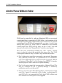
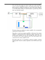
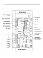
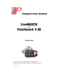
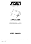
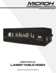
PASS – Professional Audience Safety System User Manual November 2O12 Pangolin Laser Systems 2 PASS Installation Manual Chapter 1 Introduction Congratulations on selecting Pangolin’s Professional Audience Safety System, an important decision to keep your audiences safe from the potential hazzards that a laser light projection system may pose. You have purchased the most powerful, and only patented safety hardware for laser light shows. This manual serves as a brief introduction to PASS, so you can install it and get started. Pangolin provides you with the PASS hardware board, connection cables, and this manual. You must provide a laser projector including laser, scanners and power supply. You may also use an optional light sensor and a control panel for maximum control. PASS is a sophisticated system which, when properly integrated into a laser projector and used with the proper show setup techniques, can guarantee the safety of audience scanning laser shows. PASS is barely bigger than a credit card, and yet it includes a set of very sophisticated and complete protection systems. PASS is designed with multiple levels of redundancy and with circuitry that is designed to fail-safe. In fact PASS is designed to maintain safety even in the face of five simultaneous failures. This manual discusses how to install, connect, and adjust PASS. You should read and fully understand this manual before installing and using PASS. NOTICE! Pangolin will only guarantee the proper operation of PASS when it is used in conjunction with Pangolin software and control hardware (either QM2000 or FB3). In addition, Pangolin strongly recommends the use of only Cambridge model 6210 or 6215 scanners with associated servo drivers made by Cambridge Technology. 3 Brief Theory of Operation Ideally the PASS circuit is installed inside the projector. PASS is inserted into the ILDA (analog signal) signal stream. Because of this, PASS is able to interrupt the flow of the color signals, as well as forcibly close the shutter and open the projector Interlock circuit if necessary. The following is a brief synopsis of PASS and how it operates. PASS monitors the following projector-health-related properties: Scanner power supply and internal PASS power supplies Scanner position signals to derive: o Scanning velocity o Effect size o Horizon (“Protected Area”) PASS logic system Control Panel signals, including ESTOP and Manual Reset (optional) Beam Power detected during blanking and non-blanked periods (optional) Power Supplies When power is not applied to PASS, or when PASS detects that the power supply is not sufficient to properly operate the laser projector, PASS will crowbar (short-circuit) the color signal inputs, and forcibly close the shutter and intensity outputs. PASS will also open the projector interlock signal path (ILDA pins 4 and 17). As long as the interlock signal path is used within the projector, this action prevents light from being emitted from the projector under all circumstances. 4 PASS Installation Manual Scanner Position Signals PASS monitors the X and Y position signals and derives Euclidian vector velocity as well as effect size. If the vector velocity is found to be below the Minimum Velocity (the minimum speed that the beam is required to sweep, in X and/or Y, in order to be considered to be safe), and found to remain there for a period longer than the Dwell Time (the time that a beam may remain at or below the minimum velocity see page), PASS will blank (pull to zero volts) all color signals and the intensity signal. PASS will only do this for the period of time that the beam is below the “Minimum Velocity”. As soon as the beam speeds back up, or the beam enters a non-protected area (i.e. above the horizon if enabled), PASS will allow the color signals to flow from the Input to the Output. The Effect Size has a similar result, and this is included in PASS as a measure of redundancy. If there is an effect that is scanning very quickly, and which would satisfy the “Minimum Velocity”, but if this is a very small effect, PASS will blank the color and intensity signals until the Effect Size resumes a safe level. The Effect Size is not adjustable on this version of PASS. Note that during momentary interruptions of color and blanking signals, PASS does not affect the Shutter output. Control Panel Signals A control panel can optionally be used with PASS. The control panel may have a ESTOP switch (i.e. mushroom emergency stop switch), as well as a manual reset button, which may be embodied as a keyswitch or push button. When a control panel is used with PASS, a Manual Reset is required in order to activate PASS. In most cases, this is a simple keyswitch action but could also be a simple momentary push button. And when a Control Panel is used, PASS continually monitors the ESTOP button. If the ESTOP is pressed, PASS will immediately terminate all color and intensity signals, and forcibly close the shutter. PASS will also open the projector interlock signal path (ILDA pins 4 and 17). 5 Beam Power Monitor The Beam Power Monitor is perhaps the most unique aspect of PASS. The Beam Power Monitor is able to make sure that the light coming out of the scanners conforms to what is expected. When PASS commands that no light should be emitted from the projector, PASS will verify that this is so, by observing the Beam Power Monitor. If light is coming out of the projector when it is not supposed to be, PASS will blank the color and intensity signals, close the shutter, and open the projector interlock signal path. PASS does this because this would be considered a dire problem. Likewise, if PASS detects that light is commanded from the computer, but is not coming out of the projector, PASS will take drastic action, because this could be a sign that the light sensor is not working. And finally, PASS will measure the Beam Power against a “Maximum Safe Beam Power” adjustment, and if it is exceeded, PASS will blank the color and intensity signals, close the shutter, and open the projector interlock. Any of these conditions requires the power to be recycled, or a Manual Reset. Under normal circumstances, this will never occur. There should always be congruence between commanded power and actual light coming from the projector. And light coming out of the projector above the “Maximum Safe Beam Power” level is, of course, also a sign of trouble. Pass Logic System The PASS circuitry is implemented almost entirely in analog circuitry. This is done so that the circuit can be fully validated by peers in the safety community. There are logic circuits within PASS, but these logic circuits are entirely combinatorial in nature. This means that the logic is made up of simple AND and OR statements, which can be easily validated by peers in the safety community. There are no sequential-logic circuits within PASS, nor are there any microprocessors, because these can not be fully validated. In addition to the logic used by PASS to implement the basic safety features, PASS also includes a separate layer or logic that actually watches the first logic, and verifies sanity. If there is a problem within the PASS logic, the color and intensity signals are blanked, the shutter is closed, and the projector interlock signal path is opened. The system will remain in that state until power is recycled, or until a Manual Reset is performed. 6 PASS Installation Manual Chapter 2 Layout and Connections The general layout of PASS is shown above, with connectors identified. Pangolin includes connectorized ribbon cables with PASS. These ribbon cables can be used directly, allowing minimal effort to integrate PASS within a projector. The red stripe on the ribbon cable indicates pin 1. 7 ILDA Input Ribbon Cable The ILDA Input should come directly from the DB-25 on the projector. Ideally, there should be nothing except for the included ribbon cable between the DB-25 connector and the PASS circuit board. A simple crimp-on DB-25 connector can be used, and crimped onto the ILDA Input ribbon cable provided with PASS. ILDA Output Ribbon Cable The ILDA Output connector on the PASS board should be parsed out into pairs of signals, and then directed to various components within the projector. The signals and recommended connections are discussed below. Note that since this is an IDC connector, the pin numbers do not correspond to the ILDA pin-out on a DB-25. HOWEVER, if you crimp a DB-25-connector onto the output ribbon cable, then the pins will correspond directly to the ILDA pin-out. This is because the pin designations of a DB-connector are “in-line” while the pin designations of an IDC connector are “even and odd”. Pins 1 and 2 correspond to the X+ and X- signal respectively. These should be connected to the X+ and X- input on the X-axis scanner amplifier. Pins 3 and 4 correspond to the Y+ and Y- signals respectively. These should be connected to the Y+ and Y- input on the Y-axis scanner amplifier. Note: There should NOT be a connection to the “signal ground” of any scanner amplifier. The only “ground” connection to the scanner amplifier (or amplifiers) should be from the power supply itself. Connecting to the “signal ground” on a scanner amplifier will introduce a ground loop, which may cause distorted images. See the “Power and X-Y Position Signal Connections” on the following pages. Pins 5 and 6 correspond to the Intensity/Blanking+ and Intensity/Blanking – signals respectively. These may be used for a single-color projector, but most often they are not connected. Pins 7 and 8 correspond to the Projector Interlock loop pins 4 and 17 from the ILDA connector. Note that PASS will interrupt this interlock signal in the event of a major fault and when power is not applied, so it is highly recommended that projector manufacturers implement an interlock scheme that makes use of these signals. 8 PASS Installation Manual Ideally this interlock loop should interrupt power to the lasers themselves, thus, in the event of a major problem, PASS can turn off power to the lasers. Alternatively the interlock loop may be routed to a SEPARATE shutter, that is placed just before the X-Y scanners and after the PASS light sensor (if used). Pins 9 and 10 correspond to Red+ and Red – color signals respectively. These should be connected to the RED input on a PCAOM driver or directly to a laser diode driver. Pins 11 and 12 correspond to Green+ and Green – color signals respectively. These should be connected to the GREEN input on a PCAOM driver or directly to a laser diode driver. Pins 13 and 14 correspond to Blue+ and Blue – color signals respectively. These should be connected to the BLUE input on a PCAOM driver or directly to a laser diode driver. Pins 15 and 16 correspond to Deep Blue+ and Deep Blue – color signals respectively. These are most often not used by modern RGB laser projectors and thus, can be left unconnected. If they are used, they should be connected to the DEEP BLUE input on a PCAOM driver or directly to a laser diode driver. Pins 17 and 18 correspond to Yellow+ and Yellow – color signals respectively. These are most often not used by modern RGB laser projectors and thus, can be left unconnected. If they are used, they should be connected to the YELLOW input on a PCAOM driver or directly to a laser diode driver. Pins 19 and 20 correspond to Cyan+ and Cyan – color signals respectively. These are most often not used by modern RGB laser projectors and thus, can be left unconnected. If they are used, they should be connected to the CYAN input on a PCAOM driver or directly to a laser diode driver. Note that for the color signals above, ideally, a PCAOM or Laser Diode Driver should have differential input, and you should connect both the + and – color signals from the PASS board directly to those drivers. Pins 21 and 22 correspond to the Z+ and Z – signals respectively. In most cases, these signals are not used by laser projectors directly and in fact, when used with certain pieces of Pangolin software, these signals correspond to a Safety Coordinate System. It is recommended that these be left unconnected. 9 Pin 23 is connected to the ILDA input connector pin 12. This signal is reserved by ILDA for a light sensor output, but it is essentially unused by all manufacturers. It is recommended that this pin be left unconnected. Pin 24 is connected to the ground connection of PASS. It is recommended that this only be used as a ground reference for the shutter driver, and nothing else. Pin 25 is the main Shutter output. Under normal circumstances the state of this signal will correspond directly to pin 13 on an ILDA input connector. However, in the event of a major fault, PASS will forcibly close the shutter using this signal. It is therefore recommended that this be connected to a shutter driver. For maximum safety, the shutter should be a fast type of shutter, and one which also will fail-safe. This means that in the event of a mechanical or electrical failure of the shutter, it will remain closed due to the mechanical design of the shutter. Such shutters are made by nm Laser Products (http://www.nmlaser.com). Scanner Position Signal and Light Detector Cable Pin 1 provides +5V output, which should only be connected to the PASS light sensor. Pin 2 is the PASS light sensor input, which ranges from 0V to +5V. Pin 3 and Pin 5 correspond to the Signal Ground connection of PASS. Pin 3 should be connected to the PASS light sensor. Pin 5 may or may not be connected to the scanner amplifier, depending on circumstances described below. Pin 4 corresponds to the X Position Signal. This should be connected to the X-axis scanner amplifier. Pin 6 corresponds to the Y Position Signal. This should be connected to the Y-axis scanner amplifier. 10 PASS Installation Manual Control Panel Ribbon Cable PASS may be controlled by, and may illuminate LEDs on an external control panel that is connected to PASS. Below is a description of the control panel connections. When PASS is not connected to an external control panel, then PASS will automatically reset into a “ready” state shortly after power up. When PASS is connected to an external control panel, then PASS will not power up in a “ready” state and instead, will wait for the “Manual Reset” from the control panel. Note that some jurisdictions including the U.S.A. require a manual reset in order to activate the projector after power up. The PASS control panel connector may be used to help facilitate this feature. Pin 1 is the active input that corresponds to an external Emergency Stop (ESTOP) switch, such as a pushbutton or red “mushroom” type switch. When this pin is connected to Pin 2 (ground), ESTOP is activated. When Pin 1 is left floating, then ESTOP is inactive and the projector will be allowed to operate normally. Pin 3 is the active input that corresponds to a Manual Reset. This may be connected to pin 4 (ground) through a momentary pushbutton switch or a key-switch. Pin 5 is an active input that indicates that a control panel is being used. Pin 5 must be connected to Pin 6 when a control panel is used. If Pin 5 is not connected to Pin 6, then PASS will not wait for a manual reset when power is first applied. 11 Pins 7 and 8 provide +5V to the control panel. These may be used in conjunction with LEDs on the control panel. Pins 9 and 10 correspond to Ground. These may also be used in conjunction with LEDs on the control panel. Pin 11 is an output, which corresponds to the horizon detector within PASS. If this signal is LOW, it indicates that the Y position is below the horizon (within the audience area). If this signal is HIGH (approximately 4 volts), it indicates that the Y position is above the horizon. This signal may be routed through a resistor to an LED or pair of LEDs (bi-color pair) to give an indication on the control panel as to where the beam is within the Y space. Pin 13 is an output, which corresponds to the velocity and effect size detectors within PASS. If this signal is LOW, it indicates that the beam velocity and effect size are both OK, and that PASS will not actively suppress laser output (PASS may suppress laser output for other reasons however). If this signal is HIGH (approximately 4 volts), it indicates that the beam velocity is too slow, or that the effect size is too small, and that PASS will actively suppress laser output. This signal may be routed through a resistor to an LED or pair of LEDs (bi-color pair) to give an indication on the control panel as to the disposition of the velocity and effect size. Pin 15 is an output, which corresponds to the light detector within PASS. If this signal is LOW, it indicates that the light that is detected by PASS is above the “Maximum Safe Laser Power” threshold setting. If this signal is HIGH (approximately 4 volts), it indicates that the light detected is below the “Maximum Safe Laser Power” threshold setting. Under ordinary circumstances, this will never be LOW. This signal may be routed through a resistor to an LED or pair of LEDs (bi-color pair) to give an indication on the control panel as to the disposition of the light detected by the light sensor. Pin 17 is an output, which corresponds to whether or not PASS is “ready”. Once PASS has given a “armed” indication on Pin 19, and then once the “Manual Reset” is activated (by connecting Pin 3 to Pin 4), this signal will go HIGH, indicating that PASS will allow color signals to flow through the PASS board to the internal laser projector components. This signal will remain HIGH as long as there are no major faults detected, such as a Power Supply fault, Light Detector fault, other detectable major fault, or ESTOP being activated. This signal may be routed through a resistor to an LED or pair of LEDs (bi-color pair) to give an indication on the control panel as to whether or not PASS is active. 12 PASS Installation Manual Pin 19 is an output, which corresponds to whether or not PASS is ready to be activated (“armed”). If this signal is HIGH, it indicates that the power supply is OK, ESTOP is not activated, and light is not detected and thus, PASS may be activated by performing a “Manual Reset”. This signal may be routed through a resistor to an LED or pair of LEDs (bi-color pair) to give an indication on the control panel as to whether or not a Manual Reset can be performed. If used, this LED should ideally be placed near the “Manual Reset” push button or keyswitch. Pin 12 is an output, which corresponds to whether or not the computer feeding the ILDA input has commanded that light come out of the laser projector or not. If this signal is HIGH, it indicates that the light that PASS has detected that the computer has requested more than approximately 50% beam power from the computer. If this signal is LOW, it indicates that the computer is commanding 50% or less beam power from the computer. This signal may be routed through a resistor to an LED or pair of LEDs (bi-color pair) to give an indication on the control panel as to whether or not the computer has commanded light to come out of the projector. Pin 14 is an output, which corresponds to the condition of the power supply, both within PASS and supplying the scanner amplifiers. If this signal is HIGH, it indicates that the power supply feeding the scanner amplifiers is 19 volts or higher. It also indicates that all of the power supplies within PASS itself are also within their acceptable ranges. If this signal is LOW, it indicates that there is a power supply problem of some kind. This signal may be routed through a resistor to an LED or pair of LEDs (bi-color pair) to give an indication of the state of the power supplies. 13 Status LED signals on the Control Panel connector Pin 16 is a “Status LED number 1”. If this signal is LOW, it indicates that a power supply fault has been detected. Pin 18 is a “Status LED number 2”. If this signal is LOW, it indicates that the PASS light sensor detected a light level that exceeded the “Maximum Safe Light Level” while the Y position was below the horizon. Pin 20 is a “Status LED number 3”. If this signal is LOW, it indicates that PASS tried to extinguish light from coming out of the projector, but that the PASS light detector still detected light output. This would occur if a PCAOM or Laser Diode Driver continued to output light after being told not to. This would also occur if the “Minimum light level” adjustment of PASS is not set correctly. And finally, this might also occur if PASS did not detect light coming out of the computer even though the computer commanded light output. This would indicate either a laser failure or light detector failure. Note that unlike the other LED outputs on the control panel connector, the “Status LED” outputs will “latch” in the event that a fault is detected. They will remain in the latched state until a Manual Reset occurs. This allows you to determine the cause of any detected faults. The “Status LED” signals may be routed through a resistor to an LED on the control panel to give an indication of any faults that have been detected. 14 PASS Installation Manual Pass Power and X-Y position signal connections PASS monitors the power supplies that feed the scanner amplifiers. This voltage can be between +/-20 volts and +/- 30 volts. The manor in which you connect PASS to the power supply and to the scanner amplifiers depends heavily upon whether you are using two separate single-axis scanner amplifiers, or one dual-axis scanner amplifier. If you are using two separate single-axis scanner amplifiers, the recommended connections are shown below: Note that each scanner amplifier, as well as the PASS circuit board itself must each have their own power wires going back to the power supply. These wires should all meet at the power supply itself. If you have two power supplies (one for +24V and the other for –24V) then these power supplies should establish a central connection where all wires meet. This is called a “single-point grounding scheme. Wiring the power supply in any other way will cause a ground loop, which may cause distorted images during projection. 15 Also note that when using two separate single-axis scanner amplifiers, you run only the POSITION signal to the PASS position input. DO NOT connect any additional ground wire from each scanner amplifier to the PASS board. Doing so would introduce a ground loop, which may cause distorted images. If you are using a one dual-axis scanner amplifier, the recommended connections are shown below: Since there is only one scanner amplifier in this case, the scanner amplifier is connected directly to the power supply. If you have two separate power supplies (one for +24V and one for –24V), these can be connected at the scanner amplifier itself. The PASS board is also connected at the scanner amplifier itself. Note that in this case, it is permitted to connect a separate “position signal ground” from the scanner amplifier to the PASS board if you wish. 16 PASS Installation Manual PASS Adjustments PASS includes a number of adjustments and switches that can be used to customize operation to a particular projector or projection scenario. Below you will see the PASS board and location of five adjustment potentiometers. The operation of each potentiometer is described below. 17 The Minimum Velocity controls the minimum speed that the beam is required to sweep, in X and/or Y, in order to be considered to be safe. At the factory, Pangolin sets this to 5 radians per second. Note that the scale of this control (in radians per second) depends on the actual position scale factor of the scanner amplifier being used. Turning this control clockwise increases the minimum velocity (requiring a faster-scanning beam in order to be considered safe). The Dwell Time controls the time that a beam may remain at or below the minimum velocity, before PASS extinguishes the beam. At the factory, Pangolin sets this to 1.5 milliseconds. We have found that a combination of 5 radians per second, and 1.5 millisecond Dwell Time provides a good degree of safety, while not negatively impacting normal show programming. Turning this control counter-clockwise reduces the Dwell Time, and turning this control clockwise increases it. The Dwell Time can be adjusted between 100 microseconds and 10 milliseconds. The Horizon adjusts the “Protected Area” (if Switch 3 is moved to the “on” position). At the factory, Pangolin sets this control to approximately the center of the vertical scan field, but this may be adjusted clockwise or counter-clockwise to set the horizon of the protected area as desired. Note that this control is very sensitive to rotation. You will not need to turn this control very much to explore the entire vertical area. Also note that the horizon adjustment is completely ignored if Switch 3 is turned off. (See the section about PASS Switches for more information.) The “Maximum Safe Beam Power” adjustment controls the maximum power that can be allowed into the “Protected Area”. For example, if the beam is scanning below the horizon, PASS will monitor the beam power and make sure that this beam power is not exceeded. If the beam is not scanning within the “Protected Area” (for example, above the horizon), then this control is ignored and full-power beams can be projected overhead. The “Minimum Power” adjustment controls the minimum light level that is detectable by the light sensor. Generally this is adjusted so that no light is detected by PASS when the laser is off. You can adjust the “Maximum Safe Beam Power” and “Minimum Power” adjustments by looking at D208 “Light Sensor State” bi-color LED on the PASS board. Also note that the “Maximum Safe Beam Power” and “Minimum Power” adjustments are ignored if the switch 4 is turned “on” (see switches below). 18 PASS Installation Manual PASS Switches The switches on PASS are shown below. 19 With the PASS board in this orientation, Switch 4 is at the top. When this switch is moved to the left (on), the light sensor input is ignored. You would move the switch to this position if you are not using a light sensor. When this switch is moved to the right (off), the light sensor input is monitored, and an additional level of safety is provided. Pangolin ships the PASS board with this switch turned on. With the PASS board in this orientation, Switch 3 is next in line. When this switch is moved to the left (on), the Horizon control is monitored and PASS will only allow static or slow beams above the horizon. If there is a slow-moving, or non-moving beam below the horizon, it will be extinguished by PASS. When this switch is moved to the right (off), the Horizon control is ignored, and PASS will not allow a slow-moving or non-moving beam anywhere within the scan field. Pangolin ships the PASS board with this switch turned on. With the PASS board in this orientation, Switch 2 is next in line. This switch controls the interpretation of an advanced feature of PASS called the S-coordinate. At this time, we recommend this switch be placed in the left position (on). Pangolin ships the PASS board with this switch turned on. With the PASS board in this orientation, Switch 1 is on the bottom. This switch controls where PASS gets the light sensor signal. ILDA pin 12 is defined by the ILDA standard as possibly providing feedback from a light sensor. However, since the vast majority of projectors do not use this part of the ILDA standard, we recommend that this switch be moved to the right (off). Pangolin ships the PASS board with this switch turned off. 20 PASS Installation Manual 21 22 PASS Installation Manual Registration Form Many of our customers purchase through dealers, so we don't always know who you are. To help us give you the best service and support, please fill in the form, then mail or fax it to the address on the back cover of this manual. (You can also register online at our website, www.pangolin.com.) Thank you! Contact name (primary Lasershow Player user) Company name Street address City State or province Zip or postal code Country Telephone country code (non-US) Telephone area code or city code Work/daytime phone number Fax number Other phone (mobile, nighttime, etc.) Preferred e-mail address Website (if you have one) Lasershow Player model CD 2OOO serial number Name of dealer or distributor 23 © 2008-2012, Pangolin Laser Systems, Inc. All rights reserved. Due to our policy of continuous product improvement, information in this manual is subject to change without notice. NOTICE: The electronic design of PASS as well as concepts embodied within it, are protected by multiple U.S. and Australia patents.