1
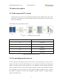
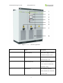
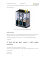
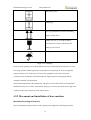
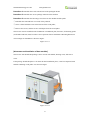
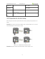
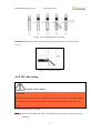
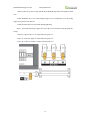
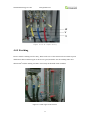
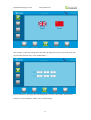
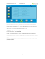
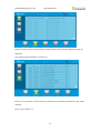
Growatt New Energy Technology CO.,LTD www.ginverter.com Growatt CP250 PV Grid-Connected Inverter Installation Manual Thank you for choosing the Growatt CP250. Growatt CP250 PV grid-connected inverter products have high efficiency, wide MPPT voltage range, advanced DSP control technology, perfect protection function enables PV systems more reliable operation, simple to operate, easy to maintain. We believe that the product will be more widely used in a variety of industrial, commercial and residential areas. Growatt New Energy CO. LTD www.ginverter.com Content 1 About this Manual .......................................................................................................................... 4 1.1 Contents .............................................................................................................................. 4 1.2 Target readers ...................................................................................................................... 4 1.3 How to use this Manual ...................................................................................................... 5 1.4 Symbols explanation ........................................................................................................... 5 2 Safety instructions .......................................................................................................................... 6 2.1 Installation........................................................................................................................... 7 2.2 Operator .............................................................................................................................. 7 2.3 Inspection and storage ...................................................................................................... 7 2.4 Transportation ..................................................................................................................... 8 2.5 Installation........................................................................................................................... 8 2.6 Repair and maintenance ................................................................................................... 9 2.7 Inverter EMC and noise level ........................................................................................... 10 2.8 Important note ................................................................................................................... 10 3 Product description ...................................................................................................................... 11 3.1 Grid-connected PV system ................................................................................................ 11 3.2 Circuit diagram the inverter .............................................................................................. 11 3.3 The layout of the main components ............................................................................... 12 3.3.1 External components ...................................................................................................... 12 3.4 Operation mode ................................................................................................................. 16 3.4.1 Standby mode ......................................................................................................... 16 3.4.2 Grid mode .............................................................................................................. 16 3.4.3 Faulty mode ............................................................................................................ 17 3.4.4 Permanent faulty mode .......................................................................................... 17 3.5 Protection .................................................................................................................. 18 3.6 Storage .............................................................................................................................. 18 3.7 Dimension ................................................................................................................. 19 3.8 Label.......................................................................................................................... 19 3.9 Packaging information .............................................................................................. 20 4 Products installation ..................................................................................................... 21 4.1 Installation condition requirements ........................................................................... 21 4.2 Tools and spare parts required for whole machine installation ................................. 24 4.3 Mechanical installation ............................................................................................. 25 4.3.1 Transportation of packaged whole machine ........................................................... 25 4.3.2 Movement and installation of bare machine .......................................................... 26 4.4 Electrical installation ................................................................................................. 28 4.4.1 Input and output requirements................................................................................ 28 4.4.2 Preparation for electrical wiring ............................................................................. 30 4.4.3 DC side wiring ....................................................................................................... 31 4.4.4 AC side wiring........................................................................................................ 33 4.4.5 Earthing .................................................................................................................. 35 4.5 Communication ......................................................................................................... 36 2 Growatt New Energy CO. LTD www.ginverter.com 4.5.1 RS485 communication ........................................................................................... 36 4.5.2 Internet communication.......................................................................................... 37 4.6 Installation inspection ............................................................................................... 37 5 Pilot operation .............................................................................................................. 38 5.1 Relevant requirements ............................................................................................... 38 5.2 Inspection .................................................................................................................. 39 5.2.1 Inverter inspection.................................................................................................. 39 5.2.2 Grid voltage inspection .......................................................................................... 39 5.2.3 DC side voltage inspection..................................................................................... 39 5.3 Power on steps........................................................................................................... 39 5.4 Pilot operation completion ........................................................................................ 40 5.5 Power off steps .......................................................................................................... 41 6 GUI instruction ............................................................................................................ 41 6.1 LCD display screen introduction............................................................................... 41 6.2 LCD operation.......................................................................................................... 42 6.2.1 Initialization ........................................................................................................... 42 6.2.2 Home page ............................................................................................................. 43 6.2.3 ON/OFF interface................................................................................................. 44 6.2.4 System setting ..................................................................................................... 45 6.2.5 Historical information ............................................................................................ 47 6.2.6 Operation data ........................................................................................................ 49 6.3 LCD display information schedule ......................................................................... 52 6.3.1 General history failure table ................................................................................... 52 6.3.2 Serious fault history ............................................................................................... 55 6.3.3 Inverter status ......................................................................................................... 56 7 Routine maintenance .................................................................................................... 56 7.1 Replacing the dust screen ........................................................................................ 56 7.2 Regular maintenance ................................................................................................. 57 7.3 Waste disposal ........................................................................................................... 58 8 Appendix ...................................................................................................................... 59 8.1 Specification............................................................................................................ 59 8.2 software version ........................................................................................................ 59 8.3 Growatt Factory warranty ......................................................................................... 60 8.4 Contact ................................................................................................................... 61 3 Growatt New Energy CO. LTD www.ginverter.com 1 About this Manual This chapter describes the contents of this manual, target reader, and safety symbols, can help users to have a better understanding of the manual. 1.1 Contents This manual applies to Growatt CP250 PV grid-connected inverters, the manual contains: safety instruction Attention that needs to be paid when operating and maintenancing the Growatt CP250. Product description The role inverter plays in the photovoltaic grid-connection system and structure, principle, protection, operation mode, storage and package size of the Growatt CP250. Installation Inverter installation conditions, tools, and the inverter mechanical and electrical installation, the communication connection and inspection. Commissioning Inspection before commissioning and procedure to turn on/off inverter. GUI(Graphic User Interface) instruction Information displayed on the inverter LCD touch-screen and setting instruction. Routine maintenance Daily maintenance of the inverter, the replacement of some spare parts and waste disposal instruction. Appendix Technical data, warranty policy and contact information. 1.2 Target readers Qualification 1)Only professional electricians or professionally qualified personnel can transport or install this product. 2)The operator should be fully familiar with the structure and working principle of the entire 4 Growatt New Energy CO. LTD www.ginverter.com grid-connected PV system; 3)The operator should be fully familiar with this manual; 4)The operator should be fully familiar with the local standards of the project. 1.3 How to use this Manual Read this manual before installation of the Growatt CP250. Store this manual where accessible at all times. The contents of this manual will be periodically updated or revised if necessary. However discrepancies cannot be excluded. Please refer to the product or download the latest version of this manual on www.growatt.com. 1.4 Symbols explanation In order to ensure the personal and property safety of the user during installation, or optimally efficient use of this product, symbols are used highlight the information. The following symbols may be used in this manual, please read carefully, in order to make better use of this manual. Caution, risk of danger DANGER DANGER indicates a hazard with a high level of risk which, if not avoided, will result in death or serious injury. CAUTION CAUTION indicates there is potential risk, if not avoided, could result in equipment malfunction and property damage. 5 Growatt New Energy CO. LTD www.ginverter.com Caution,risk of electric shock WARNING When PV array exposed to sunlight, there will be DC voltage in the equipment DC side; and when output breaker is on, there is a potential risk of electric shock. Caution, risk of fire hazard WARNING Suitable for mounting on concrete or other non-combustible surface only. Protective conductor terminal PE TERMINAL The inverter has to be firmly grounded to ensure the safety of personnel. Risk of electric shock, Energy storage timed discharge. WARNING Electrical shock danger exists in the capacitor; the cover shall be moved at least 5 minutes later after all powers are disconnected. 2 Safety instructions Inverter installation and service personnel must be trained and familiar with the general safety requirement when working on electrical equipment. Installation and service personnel should also 6 Growatt New Energy CO. LTD www.ginverter.com be familiar with the local laws and regulations and safety requirements. Read this manual carefully before operation. The equipment will not be under warranty if failing to operate according to this manual. Operation on the inverter must be for qualified electrical technician only. When inverter operating, don’t touch any electrical parts except for the touch-screen. All electrical operation must comply with local electrical operation standards. Warranty service for the inverter does not contain module maintenance. Permission from the local utility company is required before installing the PV Grid-connected system and only professional personnel are qualified for the operation. 2.1 Installation Proper installation requires following all the instructions in the user manual involving transportation, mounting, wiring and commissioning. Growatt does not cover warranty for the inverter damage due to failing to use it properly. 2.2 Operator Inverter installation and service personnel must be trained and familiar with the general safety requirement when working on electrical equipment. Installation and service personnel should also be familiar with the local laws and regulations and safety requirements. 2.3 Inspection and storage The inverter should be carefully checked before signing the document from the transportation company. Check the received items against delivery note, and if there is any defect or damage, immediately notify the transportation company. If necessary, you can seek help from Growatt Customer Service department. 7 Growatt New Energy CO. LTD www.ginverter.com CAUTION The Growatt CP250 can only be stored when it is stopped and all the doors are closed in a dry room to protect the internal circuits against dust and moisture. 2.4 Transportation Transportation should follow the transportation methods described in the user manual. The inverter's weight and center of gravity of the non-centered should be taken into account during transportation. The center of gravity has been marked on the box. Caution, risk of danger DANGER During transportation, lifting equipment and personnel must be qualified. The inverter should be placed vertically and the inclination cannot be more than 10 degrees. It is not allowed to place the inverter upside down or transport in a horizontal position. Incorrect lifting and transportation can lead to serious injury, property loss and damage to the inverter. 2.5 Installation The protection level of the inverter is IP20, which is designed for indoor installation. Please refer to chapter 4 for installation instruction. The installation location must be dry, including no expected condensation. The inverter is only for use in a closed electrical operating area. When the photovoltaic array is exposed to light, it supplies a D.C. voltage to the PCE. 8 Growatt New Energy CO. LTD www.ginverter.com Caution, risk of fire hazard WARNING Suitable for mounting on concrete or other non-combustible surface only. 2.6 Repair and maintenance Repair and maintenance can only be carried out after disconnecting the DC and AC wiring for at least 5 minutes. Only professional technical personnel are qualified for the operation. Disconnecting switches Disconnect DC switch and AC switch, and make sure the inverter will not be connected accidentally. Ensure the inverter is totally disconnected with no voltage by testing with a multi-meter. Although the DC and AC switch has been disconnected, there is still voltage in some components, for example capacitors. Hence, the repair or maintenance operation can only be proceeded at least 5 minutes after the disconnection. Maintenance and modification Only personnel with Growatt authorization are qualified for the maintenance and modification. And to ensure personal safety, use original accessories provided by the manufacturer only. Otherwise, electrical safety and EMC might not comply with the required standard. Function and safety parameters Don’t change the parameters of the inverter without authorization from the local utility and Growatt New Energy Co., Ltd. Otherwise, it might lead to injury or equipment damage and the warranty of the inverter will be voided. Risk of electric shock, Energy storage timed discharge. WARNING 9 Growatt New Energy CO. LTD www.ginverter.com Electrical shock danger exists in the capacitor; the cover shall be moved at least 5 minutes later after all powers are disconnected. 2.7 Inverter EMC and noise level Electromagnetic compatibility (EMC) is the requirement for electrical equipment that it can operate normally in the electromagnetic environment and does not cause unacceptable environmental impact itself. Anti-interference Anti-interference property from outside. Electromagnetic emission impact on the environment property from internal components. Inverter may generate some noise and electromagnetic radiation during operation. According to EMC emission and noise level, inverter should be used in industrial environments. Hence, all personnel should not stay long near the inverter. 2.8 Important note Item 1: Static electricity can cause damage to the inverter Electrostatic discharge may cause unrecoverable damage to inverter internal components! When operating the inverter, operator must comply with anti-static protection norms! Item 2: Restriction The inverter cannot be directly used to connect the life support equipment and medical equipment! Item 3: Precautions Make sure installation tools or other unnecessary items are not left inside the inverter before starting up. Item 4: Maintenance notice Maintenance can only be carried out after the inverter totally discharged. 10 Growatt New Energy CO. LTD www.ginverter.com 3 Product description 3.1 Grid-connected PV system Growatt CP series inverters are grid-connected central inverters which convert DC current generated by PV modules into AC current and feed it into the public grid. PV inverters always act as key components. Grid-connected PV system shown as below Figure 3‐1 Grid-connected PV system No. Name A PV module B PV combiner box C Inverter D transformer E utility grid 3.2 Electrical schematic of the inverter 3.2 Circuit diagram the inverter Growatt CP250 PV grid-connected inverter converts DC current generated by PV array into AC current. Then the AC current is filtered into sine wave electricity and fed into the utility grid through a medium-voltage isolating transformer. The additional external isolating transformer shall be connected between inverter and local power grid by customers. This transformer shall be met requirement of local grid and tests about external isolating transformer must be passed successfully according to relevant safty standards! (clearance distance, creepage distance, dielectric strength test etc. ) 11 Growatt New Energy CO. LTD www.ginverter.com Figure 3-2-1 Growatt CP250 circuit diagram CAUTION Although the Growatt CP250 is no inner transformer, transformer is needed for solar power station. 3.3 The layout of the main components 3.3.1 External components External main components include: LED indicator, LCD touch screen and start-stop knob, emergency stop button, the DC side switch and the AC side switch. 12 Growatt New Energy CO. LTD www.ginverter.com Figure 3‐3‐1 ‐1 Inverter appearance No. Name Descripition 1 Power indicator When power supply is normal, the indicator displays yellow. 2 Inverter malfunction indicator When inverter is faulty, the indicator displays red. 3 touch Screen LCD Operation information display, receive control command and parameters setting 4 Off-on knob only control the grid-side switch, and does not control the DC-side switch 13 Growatt New Energy CO. LTD 5 www.ginverter.com Emergency STOP Shut down the inverter when pressed down 6 DC Switch connect or disconnect the inverter and PV modules 7 Grid Switch connect or disconnect the inverter and utility grid 8 Dust screen prevent dust from entering into the inverter Figure 3‐3‐1 Part description Indicator The inverter is designed intelligently, which will automatically start and stop working every day. There are two LED indicators on the inverter which is used to display the current status of the inverter. Figure 3‐3‐1‐2 LED indicators LED Description POWER The indicator lights when power supply to the inverter is normal. FAULT The indicator lights when power supply to the inverter is normal. Figure 3‐3‐2 LED status AC/DC main switch AC switch is used to connect or disconnect the inverter and utility grid. DC switch is used to connect or disconnect the inverter and PV modules. If the AC switch is used in the case of load, the inverter components will be exposed to considerable stress. Frequent use of the AC switch will 14 Growatt New Energy CO. LTD www.ginverter.com lead to damage of the inverter. Emergency STOP CAUTION The emergency stop button is only used in case of emergency, such as: serious failure in the grid, fire, etc. Figure 3‐3‐1‐3 Emergency STOP The emergency stop button immediately disconnects the inverter from both grid and PV arrays, which ensure the safety of the inverter. By pressing the emergency stop button, the device will be locked in the "off" position. Only release the emergency stop button by rotating it clockwise and closing AC, DC breaker, can the inverter resume working normally. Off-on knob It is used to start or stop the inverter. 15 Growatt New Energy CO. LTD www.ginverter.com Figure 3‐3‐1‐4 Off-on knob Touch screen It displays the inverter’s operating parameters, power generation, and faulty information record. Please refer to Section 6, for details. 3.4 Operation mode There are several operation modes of the inverter. 3.4.1 Standby mode The standby mode refers to powering up the inverter for the first time since installation, but there is not enough power to connect to the grid. When there is enough power from the PV array, it will transfer to grid mode. 3.4.2 Grid mode Process of inverter connecting to the grid: 1) PV array connects to the inverter input, and the inverter output connects to transformer, then to the utility grid; 2)Close AC and DC breaker and inverter will enter into standby mode. 3)When input voltage exceed 450V (inverter startup voltage can be set on LCD, minimum voltage is 450V), the inverter will connect to the grid. 16 Growatt New Energy CO. LTD www.ginverter.com 4) Grid-connected inverter will check if the current state meets all the conditions to connect to the grid before it actually connects. The power generation is automatic. The inverter will detect if DC input and AC grid meets all conditions. When all conditions are met, it will enter into grid mode. When the grid is abnormal, inverter will immediately disconnect from the utility grid, and immediately enter into the fault state. In this mode, inverter will convert the DC power into AC power and feed into the grid. Meanwhile, inverter will output the power from the PV array in the MPPT (Maximum power point) method, and grid mode is also called MPPT mode. CAUTION When the ambient temperature is too high, it is normal the inverter reduces the output power. However, if this frequently happens, check the cooling surface of the inverter or place the inverter in better ventilation conditions place. If the inverter fan is dirty, please clean the fan, if there is problem with the inverter internal electrical, please seek help from professional services. 3.4.3 Faulty mode When the PV power system failure, the inverter will immediately disconnect the AC contactor and enters into the fault mode, so as to ensure the safety of the system. Inverter continuous monitors if the fault is eliminated. The inverter will not enter into the grid mode until the fault is eliminated. 3.4.4 Permanent faulty mode When the PV power system is in serious failure, the inverter will immediately disconnect the AC contactor and enters into the Permanent fault mode, so as to ensure the safety of the system. For example: inverter module failure etc. When inverter enter into permanent failure mode, do not repair the inverter, and you should get in touch with the local dealers or call Growatt customer service department for help. 17 Growatt New Energy CO. LTD www.ginverter.com 3.5 Protection Anti-islanding When the local power grid shutdown due to malfunction or maintenance of equipment, the inverter will be physically cut off the connection to the grid, in order to protect operating personnel working in the electricity grid, and the inverter is in compliance with the relevant standards. Lightning protection Inverter built-in lightning protection module has the DC / AC side lightning over-voltage protection to avoid inverter from being damaged. More protection features, please refer to the section 6.3. 3.6 Storage If there is a long time before installation or operation, the Growatt CP 500TL should be stored appropriately. The packaging should be restored to its original state; Retain the desiccant in the packaging. The Growatt CP 500TL can only be stored when it is stopped and all the doors are closed in a dry room to protect the internal circuits against dust and moisture. Storage temperature range: -40~55 ℃ Storage relative humidity range: 5 %~95 % Operating temperature range: -25~55 ℃ Operating relative humidity range:5 %~95% Max. altitude:2000 m 18 Growatt New Energy CO. LTD www.ginverter.com CAUTION! Strictly prohibited storage without packing! Avoid storage in direct sunlight! Keep upright and no stacking on top of the crate. 3.7 Dimension Model Growatt CP250 Size(W*H*D mm) 1600*2100*850 Dimension 3‐7 Inverter dimension 3.8 Label Inverter label is affixed on the inverter, which contains model and specification information. Do not attempt to tamper with the label information, and the inverter will not be under warranty if the label information is altered, vague or disappeared. 19 Growatt New Energy CO. LTD www.ginverter.com Figure 3‐8 product label 3.9 Packaging information No. Name Unit quanti description ty 1 inverter main unit pcs 2 user manual pcs 1 3 certificate pcs 1 4 OT terminal pcs 1 Contains cabinet keys 8 Table 3‐9 Packaging information 20 Growatt New Energy CO. LTD www.ginverter.com 4 Products installation 4.1 Installation condition requirements To ensure normal operation of the machine, the installation environment is required as follows: The ingress protection of inverter is IP20. Moreover, as this product is an electronic equipment, it shall not be placed in humid environment; Install indoors and avoid sunlight and rain; Ventilation of the room shall be good; The installation environment shall be clean; As some noise will be produced in operation, this equipment shall be installed far from residential quarters; The installation ground shall be even enough, and firm enough to support the weight of inverter; The installation position shall be convenient for maintenance; Ambient temperature range: –25°C~55°C; Appropriate space shall be reserved for the machine to ensure ventilation and cooling. We suggest inverter is installed in the distribution room. The floor, wall clearance, Ventilation equipment and precaution should be designed by professional personnel and satisfy the following requirements. [Foundation requirement] Inverter is required to install on even ground with fire-retardant material as the surface or channel steel support structure, and sag or tilt ground is prohibited. The foundation shall be solid, safe and reliable. The foundation shall be capable of bearing the load of the inverter. Its load bearing ability shall be concerned throughout the installation place selection. [Clearance space] During installation of the inverter, appropriate space shall be left to the wall or other equipments, in order to satisfy the requirements on narrowest maintenance channel, emergency access and ventilation. In front of the installation place of inverter, a space of 1.5m or more shall be ensured, the back 21 Growatt New Energy CO. LTD www.ginverter.com 0.6m or more, the top 0.6m or more to ensure easy installation, cooling and maintenance. Figure 4-1-1 required Clearance space [Cable trench] The cable connection of inverter adopts bottom inlet and bottom outlet. Cable trenches are recommended. The cable trenches are often designed and constructed by the construction side based on relevant standards, with the equipment weight and dimensions required to be considered. Good electrical connection is needed between different cable trenches and GND terminals. [Wiring specification] Cables in the inverter can be classified into either power cables or data cables. In cabling, the power cable shall be kept far away from, and the cable shall be kept in right angle at cross. The cable shall be as short as possible, and an appropriate distance shall be kept to the power cable. We suggest the DC PV+ and PV- insulation resistance is more than Vmax PV/30mA. The power cable and data access shall be placed in different cable trenches respectively to avoid lengthy routing between the power cable and other cables, so as to reduce the electromagnetic interruption caused by sudden change of the output voltage. The distance among the power cable and data access shall be more than 0.2m. When the cables are crossed, the cross angle shall be 90 22 Growatt New Energy CO. LTD www.ginverter.com degrees, while the distance can be reduced appropriately. Inverters for use with ungrounded arrays shall have means to measure the DC insulation resistance from the PV input (array) to ground before starting operation. [Ventilation requirement] In operation, inverter will produce a lot of heat. When ambient temperature is too high, the electrical property of the equipment may be affected, the equipment may even be damaged. Therefore, the heat release shall be fully considered in designing the control room to ensure operation of the equipment in high efficiency. [Ventilation environment] To satisfy the ventilation requirement of inverter, its installation environment shall meet the following conditions: ※ Inverter shall be prevented from being installed in the place of poor ventilation condition and insufficient air flow; ※ The air inlet shall have enough air supplementation. [Ventilation equipment] To ensure safe and reliable operation of the equipment, the ambient temperature must be within the permission range –25°C~55°C, therefore, appropriate ventilation devices must be equipped with to release the heat generated by the equipment. We suggest the ventilation rate is more than 10000m³/h. ● There must be ventilation equipment inside the distribution room to ensure release of the waste heat generated by the inverter from the equipment, and allow for maximum ambient environment temperature. This can be realized from installation of exhaust devices; ● Another fan can be added at the air duct outlet to exhaust the air out and ensure balanced pressure; ● The direction of the air outlet shall be selected according to the local actual wind direction; ● Pay attention to the dustproof measures and waterproof design at the air inlet and outlet; 23 Growatt New Energy CO. LTD www.ginverter.com ● If more air ducts are required, its dimensions shall be designed by the professionals according to the air output amount. Figure 4-1-2 Inverter internal ventilation diagram [Other protections] With IP20 of protection level, inverter is appropriate to be installed in dry and clean environment. Meanwhile, water leakage of the house shall be prevented, as it may damage the inverter. According to EMC requirement and noise level, the inverter shall be installed in industrial environment. 4.2 Tools and spare parts required for whole machine installation Tools and spare parts required for installation is as follows: ● Hoisting crane, forklift or fork lift truck (with the capacity for bearing the weight of the inverter) ● Torque wrench ● Screwdriver ● Wire stripper 24 Growatt New Energy CO. LTD www.ginverter.com ● Terminal crimping machine ● Heat dryer ● Megger and multimeter 4.3 Mechanical installation 4.3.1 Transportation of packaged whole machine 【NOTE】 This inverter is transported as an integrated unit, and the user can hoist it from the bottom with a forklift, or move it with a hoisting crane or crane. Note 1: The inverter is integrated and cannot be dissembled either in transportation or installation. Any fault attributed to modification unauthorized by the Growatt is beyond the quality assurance. Note 2: In movement, tilt, violent shake or sudden force upon the inverter shall be prevented, such as sudden down of lifting. Note 3: Please read carefully the labeled parameters to select an appropriate transportation means and storage place. We suggest the user make use of forklift to move the inverter if possible. CAUTION! Before the inverter is moved to the designated place, we suggest to lay the DC input cable and AC main power supply cable. As these cables are relatively thick, they are hard to be cabled after the inverter is installed. To keep the equipment in a better protective status, please adopt transportation with package as much as possible, and comply with the labels printed on the package in transportation: Sign indication 25 Growatt New Energy CO. LTD www.ginverter.com The gravity centre Lifting logo Face up to prohibit the inverter horizontally, tilted or upside down Handle with care, to avoid the transport environment too intense collision friction damage to the inverter Keep away from moisture Figure 4-3-1 Packaging Inverters whose packages are not demolished can be moved with forklift, hoisting crane or crane. In moving, attention shall be paid to the weight painted on the package to ensure enough load capacity of the devices. As the gravity center of the equipment locates at the lower place symmetrical in front and back and left and right, the support point or hoisting point shall be arranged reasonably in transportation. The forklift transportation is the standard one. The gravity center of the cabinet in transportation should locate between two forks of the forklift. The big-size inverter may block driver's sight, and it shall be treated with cooperation of the aid personnel. 4.3.2 Movement and installation of bare machine [Demolish the package of inverter] Please demolish the packaged cabinet of the equipment according to the following procedures: 26 Growatt New Energy CO. LTD www.ginverter.com Procedure 1: Demolish the wood side and roof of the packaged cabinet Procedure 2: Demolish the out-set package material on the machine Procedure 3: Demolish the fastening screws between the machine and the pallet ① Demolish the front and back cover lids of the pedestal; ② Screw off the hold-down nuts at the bottom of the wood pallet; ③ Remove the screws, and the inverter will depart from the wood pallet. The inverter must be installed on the foundation or foundation plate, therefore, all fastening points (wall anchor and bolt) must be at their correct positions before installation. Mounting dimension of foot margin on foundation is shown in Figure. Figure 4-3-2-1 [Movement and installation of bear machine] The inverter with demolished package can be moved with forklift, hoisting crane, slide rail or crane. If the package demolished place is far from the final installation place, it can be transported with forklift containing wood pallet. It is shown in Figure. Figure 4-3-2-2 27 Growatt New Energy CO. LTD www.ginverter.com Figure 4-3-2-3 Caution, risk of danger CAUTION! We must act slowly and gently when transporting the inverter with forklift to avoid violent vibration of the inverter or collision with other objects. 4.4 Electrical installation 4.4.1 Input and output requirements Caution, risk of danger CAUTION! There is a danger of electrical shock of high voltage in inverter’s operation; only electricians of professional skills can operate. All connections with this equipment shall be done under non-voltage state. The inverter may be damaged if input or output terminal is incorrectly plugged. Failure of acting upon this information may cause serious personnel injury or significant property 28 Growatt New Energy CO. LTD www.ginverter.com loss even to death. 1) PV array The positive and negative open-circuit voltage of the PV array shall not exceed 1000, otherwise, the equipment will be in over-voltage protection state, and cannot work normally. The power of inverter PV array can be 575KW. Model Growatt CP250 PV Array Power Limit 285KW PV Array Open-circuit Voltage Limit 1000V 2) Three-phase grid Inverter will continuously inspect whether the grid satisfy the grid connected conditions. The following is the grid limit for satisfaction of local Grid connected Conditions (requirements in different countries may vary, the value can be setup and please refer to local grid connected regulations for details), and the grid is three-phase grid. Meanwhile, it shall be permitted by local power supply department before install Grid-connected inverted power. Model Growatt CP250 Grid Voltage Limit 310V~ 450V Grid Frequency Limit 45HZ-55HZ/55HZ-65HZ 3) Cable requirements Cable (Cu) Cable Diameter Requirements Aperture (mm2) Model Growatt CP250 PV Array PV+ 2*75 mm², or 185 mm² Φ10,30N*m PV Array PV- 2*75 mm²,or 185 mm² Φ10,30N*m Grid Phase A 2*70 mm²,or 240 mm² Φ10,30N*m 29 Growatt New Energy CO. LTD www.ginverter.com Grid Phase B Φ10,30N*m Grid Phase C Φ10,30N*m Earth Wire More than 120 mm² or 2* 35mm² Φ10,30N*m Green and yellow Communication 0.75mm²,shielded Twisted pair / Wire 4.4.2 Preparation for electrical wiring Before wiring, the users need to open the front door of inverter, and the specific procedures are as follows: Procedure 1: Cut off the circuit breaker at DC&AC sides. As shown in Figure 4-4-2-1, move the Grid switch and the PV switch to the state of "OFF". Figure 4-4-2-1 AC&DC Main Switch Status Schema Procedure 2: Open the front door. The unlock schema is shown in Figure 4-4-2-2. 30 Growatt New Energy CO. LTD www.ginverter.com Figure 4-4-2-2 Open Machine's Front Door Procedure 3: Raise the detents, and then close the doors. The schema is shown in Figure 4-4-2-3. Figure 4-4-2-2 Raise the detents 4.4.3 DC side wiring Caution, risk of danger CAUTION! The positive and negative of the PV array shall not be connected in reverse. A multimeter shall be used to determine the polarity first, and then connect into the corresponding input ends of the inverter. DC side wiring method is as follows: Step 1:Disconnect the higher DC side power distribution circuit breaker, the DC side wiring uncharged. 31 Growatt New Energy CO. LTD www.ginverter.com Step 2:Measuring the open-circuit voltage of the PV array with a multimeter to ensure within the allowable range. Step 3:With a multimeter to confirm the positive and negative. Step 4:Stripped end of the cable insulation Step 5:Crimp the copper nose 1. The copper core part of the strip good pressure line into the wiring copper nose hole 2. Terminal Crimping Machine the the wiring copper nose pressed. Crimp the number should be more than two Step 6:Install heat shrink tubing 1. Select cable size is more in line with the heat shrink tubing, choose the length of about 5cm 2. Heat shrinkable sleeve over in the Wiring copper nose, to completely cover the wiring copper nose pressure line hole fit 3. With a hot hair dryer to heat shrink tubing tightening Step 7:Connect "DC +" cable to the convergence box or the output of the PV array positive 1. Selection and wiring copper nose meets the bolt 2. To be the wiring copper nasal tightening in the AC wiring copper rafts 3. Fastening bolts with a screwdriver or wrench Step 8:"DC-" end to the combiner box or the negative electrode of the photovoltaic array output connected inverters in accordance with the method of Step 7 Step 9:Confirm the wiring is already firmly 32 Growatt New Energy CO. LTD www.ginverter.com Figure 4-4-3 DC input wiring 4.4.4 AC side wiring Caution, risk of danger CAUTION! When connecting the AC grid, cut off the circuit breaker at the AC side to ensure that the AC wire connecting to terminals has no electricity. AC side of the inverter and the grid side wiring method is as follows: Step 1:Disconnect the grid side disconnect switch, disconnect the inverter AC open space, with a multimeter measurements confirm that the terminal block power outage. Step 2:Make sure the AC connection cable order Step 3:Stripped end of the cable insulation Step 4:Crimp the copper nose. 1. The of stripping good thread bare copper conductor part on the wiring copper nose pressure line hole 2. The wiring copper nose pressed Crimping Machine, crimping the number should be in the more than two Step 5:Install heat shrink tubing 33 Growatt New Energy CO. LTD www.ginverter.com 1. Select cable size is more in line with the heat shrink tubing, choose the length of about 5cm 2. Heat shrinkable sleeve over in the Wiring copper nose, to completely cover the wiring copper nose pressure line hole fit 3. With a hot hair dryer to heat shrink tubing tightening Step 6:Selection and wiring copper nose meets the screw connection with the grid side wiring 1. The AC output of the "U" is connected to the grid "L1"; 2. The "V" of the AC output is connected to the grid "L2"; 3. The "W" of the AC output is connected to the grid "L3"; 34 Growatt New Energy CO. LTD www.ginverter.com Figure 4-4-4 AC output wiring 4.4.5 Earthing Inverter must be earthing well for safety; Please make sure of the connection between PE in power distribution cabinet and PE copper in the inverter good; and make sure the earthing cable more than 185mm2 and the earthing resistance must satisfy the demand of IEC standard. Figure 4-4-5 PE copper in the inverter 35 Growatt New Energy CO. LTD www.ginverter.com Caution, risk of fire hazard WARNING There is usually no need to connect DC input terminal with earth for Silicon solar cell; But for thin-film solar cell, if one of DC input terminal need to be connected to earth, GFDI device must be used for safety. All wiring into the channel at the bottom of the inverter to be all the wiring is completed, the connection port must be sealed with dust cotton, to prevent dust from entering the inside of the inverter. Caution, risk of danger CAUTION! Please do not change the connection of earthing wire that already being, for that may be cause some danger. 4.5 Communication The inverter of Growatt CP series has various communication methods. When the user needs to monitor the operating status of PV power generation system, we provide single-machine and multi-machine control programs, and diversified communication interfaces for customer's selection. 4.5.1 RS485 communication The inverter, through RS485 tandem, is connected with the PC for communication through RS485/RS232 adaptor. Inside the PC, a multi-machine monitoring software ShineNet independently developed by the Growatt is monitoring in real time the operating status of all inverters, as shown in Figure 4-5-1. The RS485 wire should be less than 1000m. 36 Growatt New Energy CO. LTD www.ginverter.com Figure 4-5-1 RS485 Multi-machine Communication 4.5.2 Internet communication There is an Ethernet port on the right side of LCD. Please connect the LCD and Router with Network cable; and then router can make data interaction with serve, and users can communicate with the inverter by internet. Figure 4-5-2 Internet Communication 4.6 Installation inspection Before the inverter is put into operation, it shall be inspected for installation. Two working men or more shall inspect to ensure correct installation of all installation according to the following table. Mechanical Installation Items Inspection □ □ □ □ □ □ No deformation and damage to inverter. Inverter's bottom is fixed, and the support is stable and reliable. Enough space is left around inverter. The ambient temperature, humidity and ventilation satisfy requirements. Smooth flow of cooling air. Complete and reliable sealing protection of cabinet. 37 Growatt New Energy CO. LTD www.ginverter.com Electrical Installation Inspection □ □ □ □ Complete and firm grounding of inverter. □ Correct connection of communication lines, and maintaining a certain distance to other cables. □ □ Correct and legible mark of cable No. Grid voltage matching the rated input voltage of inverter. Correct phase sequence of grid connection, and tightening torque meeting requirements. Correct connection of DC input anode and cathode, and tightening torque meeting requirements. Complete and reliable insulation shields, and legible and firm label of danger warnings. Other Inspections □ All useless conductive parts tied with insulating ribbon. □ No tools, spare parts, conductive dust generated from drilling or other matters left inside the cabinet. □ No condensed humidity or icing inside the cabinet. Table 4-6 Installation Inspection List 5 Pilot operation The chapter will introduce the procedure of pilot operation, including checking PV array voltage, input and output connecting, other preparation working. 5.1 Relevant requirements Before pilot operation, the installation conditions of the equipment shall be examined thoroughly, in particular whether voltages at DC and AC ends are consistent with inverter's requirements, and whether the polarity etc. are correct. Inspect if the system connection meets requirements in relevant standards or codes and if the system is grounded well. CAUTION! Before pilot operation, all switches at AC side and DC side shall ensure to be cut off. 38 Growatt New Energy CO. LTD www.ginverter.com 5.2 Inspection 5.2.1 Inverter inspection Before power on the inverter, please carry out inspections as the following procedures: Procedure 1: Inspect inverter's installation and wiring conditions based on the Installation Inspection List in Table 4-6; Procedure 2: Ensure the AC&DC circuit breakers are cut off; Procedure 3: Ensure the emergency button is available and woks normally. 5.2.2 Grid voltage inspection ● Inspect whether the three phases of the inverter is correctively connected with the three phase sequence of the grid. ● Inspect whether the line voltage and frequency are within the prescribed range, and record the value. ● If possible, measure the phase THD (Total Harmonic Distortion), and inspect the curve. If distortion is serious, the inverter may fail to operate. 5.2.3 DC side voltage inspection The DC side shall be connected to the inverter from the Combiner or DC distribution cabinet. ● Ensure correct DC input polarity. ● Measure and record the DC (open-circuit) voltage of each line. Voltages of each line shall be similar, and less than the permitted maximum DC voltage value. 5.3 Power on steps ● First power-on Operation procedures for the first power-on and operation of inverter are as follows: Procedure 1: Screw the handle of circuit breaker at the AC side to "ON" position. Procedure 2: Screw the handle of circuit breaker at the DC side to "ON" position. 39 Growatt New Energy CO. LTD www.ginverter.com Procedure 3: It takes about 10 seconds to automatically initialize the power inverted circuit and equipment. Than the "POWER" LED lamp on control panel will be on. Procedure 4: If the DC voltage is lower than the starting voltage (equal to 450Vdc), the touch screen keeps shown "Waiting" (in standby). Procedure 5: If the DC voltage is higher than the starting voltage (equal to 450Vdc), the inverter will inspect the grid connected conditions. When conditions are satisfied, it will automatically switch to "Normal ", at this moment, the "OPERATION" lamp will be on. ● Automatic power-on When the power-on conditions both at DC and AC sides are satisfied, the inverter will be powered on automatically. After the DC input or AC grid fault is demolished, the inverter will also be powered on automatically. ● Manual power-off In the operation process of the inverter, we can power off the machine through the "OFF" button on the panel. At this moment, the inverter stops work, and stops to transmit the DC energy to grid. CAUTION! After manual power-off, the machine must be powered on manually, otherwise the inverter is unable to power on. It still maintains voltage after manual power-off! 5.4 Pilot operation completion The following procedures shall be carried out after the inverter is grid connected. Procedure 1: Inspect whether abnormity exists in the inverter, such as excessive noise, excessive heat, abnormal smell or smoke. Procedure 2: Measure whether inverter connected grid voltage, current and THD are stable. Procedure 3: Operate LCD control panel and inspect whether it displays normally and accurately. 40 Growatt New Energy CO. LTD www.ginverter.com By now, the pilot operation of inverter is fully completed, and we can enter the daily operational maintenance. 5.5 Power off steps CAUTION! After the inverter is completely powered off, the general PV switch at solar panel side and the Grid switch at grid side still maintain voltage. If operations are need, please be sure to cut off the outer power completely, and wait for not less than 5 minutes. 1. Exercise the OFF button on LCD operation panel; 2. Cut off PV SWITCH; 3. Cut off GRID SWITCH; 4. Cut off the switch of DC distribution cabinet or combiner; 5. Cut off the switch of AC distribution cabinet. 6 GUI instruction 6.1 LCD display screen introduction User can view the information of the inverter operation on the LCD touch screen, as well as setting the operating parameters. In order to facilitate the operation, a menu is provided below. 41 Growatt New Energy CO. LTD www.ginverter.com Table 6-1 Growatt CP250 LCD Menu After powering on the LCD, it will initialize itself first, and then enter the boot which displays the progress bar of starting up. The main interface will display after finishing the startup (about 20S, if the progress bar has not been finished after 60S, there is communication problem between LCD and control board). Then you can begin to read the information and set the parameters. Inverter communication state, station number and system time is displayed at the top of each page of the LCD. Each page has five commonly used function keys: "run data" “historical information” "system settings" “Home” at the below of the page. The five commonly used keys corresponding sub-menu are under the button, and it will be marked green after selected. 6.2 LCD operation 6.2.1 Initialization Initialization interface: The initialization interface will be divided into two parts, the LCD initialization and inverter initialization. LCD initialization: it will be finished after powering up for 20S. Inverter initialization: After LCD initialization completed, the inverter boot screen will pop up. The initialization progress will be displayed on the LCD. After finishing initialization which takes about 30S, it will automatically switch to [home page], and operation on the LCD can be 42 Growatt New Energy CO. LTD www.ginverter.com proceeded. Note: The default language is Chinese. 6.2.2 Home page Clicking “Home” button in any interface will enter into the Home page. The operating status of the inverter output power, safety standard, model, input and output voltage, current information can be viewed in the page. Pressing the following key can switch to other pages. 43 Growatt New Energy CO. LTD www.ginverter.com 6.2.3 ON/OFF interface Clicking “ON/OFF” button in any interface will enter into this interface. There are “ON” and“OFF” button which is used to turn on and turn off the inverter. After selecting, a sub-window will pop up for confirmation: Yes/No. 44 Growatt New Energy CO. LTD 6.2.4 www.ginverter.com System setting Clicking “System setting” button in any interface will enter into this interface. Submenu: language settings, time settings, inverter information, maintenance. Pressing the left button can enter into the corresponding submenu interface. The default one is language setting interface. Language Settings: Select language, currently it only supports Chinese, English (default language is Chinese). 45 Growatt New Energy CO. LTD www.ginverter.com Time settings: system time setting (if the date and time displayed on LCD is not inconsistent with the actual date and time, they can be modified here) Device Information: This page shows the manufacturer, inverter serial number, hardware and software version information, and the date of manufacturing. 46 Growatt New Energy CO. LTD www.ginverter.com Maintenance: the interface requires a password to login. It is for electrician and maintenance personnel who are fully familiar with the structure and working principle of the PV grid system only, in order to avoid damage to personal safety and the inverter. 6.2.5 Historical information Clicking “historical information” can enter into the sub-menu of the "historical information". The submenu includes: The inverter ON and OFF time record, history of failure, serious historical failure. The inverter ON and OFF time record: ON and OFF time record can be found in a total of 20 by pressing the flip button. 47 Growatt New Energy CO. LTD www.ginverter.com History of failure: all the common history of failure details can be found by flipping the page up and down. The common fault information, see table 6.3.1. History of serious failure: a total of 20 items of historical serious failure information can be found in details. Please refer to table 6.3.2. 48 Growatt New Energy CO. LTD www.ginverter.com 6.2.6 Operation data Clicking the “Operation data” in any interface will enter into the submenu of “operation data”. The sub-menu includes: real-time data, the power curve, and energy yield figure. Pressing the left button can enter into the corresponding sub menu interface. The default interface is the real-time data interface. Insert USB Disk on the back of the LCD display, and the real time operation data will be stored in the USB Disk in every minute. Inverter will create a “CSV” format file every month in the USB disk for data storage. Real-time data: current PV power generation parameters and real-time data including the grid voltage, the grid frequency, the grid current, DC input voltage, DC input current, the internal temperature of the chassis as well as the total power generation time (updated in real time). When total power is more than 100,000KW, it will be measured by MK; when total power is less than 100,000KW, it will be measured by KW. 49 Growatt New Energy CO. LTD www.ginverter.com Power curve: daily yield displayed in bar chart (updated every 12 minutes). Energy yield: Clicking this button can enter into submenu. Monthly yield: daily yield displayed in bar chart (updated every 12 minutes). 50 Growatt New Energy CO. LTD www.ginverter.com Yearly yield: monthly yield displayed in bar chart (updated every 12 minutes). 20 years yield: yearly yield displayed in bar chart. 51 Growatt New Energy CO. LTD www.ginverter.com Pressing "Back" can return to “real time data”. 6.3 LCD display information schedule 6.3.1 General history failure table No. information 1 DC_Inverse_Failure 2 IGBT_Failure 3 EEPROM_Write_Failure 4 EEPROM_Read_Failure 5 AC_MainContactor_Failure 6 AC_SlaveContactor_Failure 7 GFDI_Failure 8 GFCI_Failure 9 DC1_VoltHigh_Fault 10 DC2_VoltHigh_Fault 11 DC1_CurrHigh_Fault 52 Growatt New Energy CO. LTD www.ginverter.com 12 DC2_CurrHigh_Fault 13 DC1_Insulation_Fault 14 DC2_Insulation_Fault 15 DC1_OCP_Fault 16 DC2_OCP_Fault 17 INT_DC1_OverVolt_Fault 18 INT_DC2_OverVolt_Fault 19 INT_DC1_OverCurr_Fault 20 INT_DC2_OverCurr_Fault 21 IGBT_Module1_Fault 22 IGBT_Module2_Fault 23 L1_OCP_Fault 24 L2_OCP_Fault 25 INT_L1_OverCurr_Fault 26 INT_L2_OverCurr_Fault 27 AC_NoUtility_Fault 28 AC_GridPhaseSeque_Fault 29 AC_PLL_Fault 30 AC_Volt_Unbalance_Fault 31 AC_Curr_Unbalance_Fault 32 AC_WU_OverVolt_Fault 33 AC_WU_UnderVolt_Fault 34 AC_VW_OverVolt_Fault 35 AC_VW_UnderVolt_Fault 36 AC_UV_OverVolt_Fault 37 AC_UV_UnderVolt_Fault 38 AC_OverFreq_Fault 39 AC_UnderFreq_Fault 40 AC_GridCurr_DcHigh_Fault 53 Growatt New Energy CO. LTD www.ginverter.com 41 AC_L1Curr_DcHigh_Fault 42 AC_L2Curr_DcHigh_Fault 43 AC_GridCurr_High_Fault 44 AC_L1Curr_High_Fault 45 AC_L2Curr_High_Fault 46 AC_Overload_Fault 47 AC_Lightload_Fault 48 AC_BackFeed_Fault 49 LVRT_Fault 50 Module1_OverTemp_Fault 51 Module2_OverTemp_Fault 52 Inductor1_OverTemp_Fault 53 Inductor2_OverTemp_Fault 54 Transformer_OverTemp_Fault 55 LowTemp_Fault 56 EPO_Stop 57 KeyEmergencyStop 58 LcdEmergencyStop 59 Door_Open_Fault 60 AC_MainContactor1_Fault 61 AC_MainContactor2_Fault 62 AC_MainContactor3_Fault 63 AC_SlaveContactor_Fault 64 GFDI_Ground_Fault 65 GFDI_HallSense_Fault 66 GFDI_AirSwitch_Fault 67 GFDI1_Fault 68 GFDI2_Fault 69 RISO1_Fault 54 Growatt New Energy CO. LTD www.ginverter.com 70 RISO2_Fault 71 GFCI1_Fault 72 GFCI2_Fault 73 AC_Fuse1_Fault 74 AC_Fuse2_Fault 75 Fault_Feedback_Warning 76 Fan_1_Fault_Warning 77 Fan_2_Fault_Warning 78 Fan_3_Fault_Warning Table 6.3.1 General history failure table 6.3.2 Serious fault history No. information 1 Grid voltage too high 2 Grid voltage too low 3 Grid frequency too high 4 Grid frequency too low 5 DC over-voltage protection 6 DC over-voltage protection 7 AC current unbalanced 8 Grid voltage unbalanced 9 PV Ground fault protection 10 AC over-current protection 11 LVRT protection 12 inverter internal problem protection 13 DSP problem protection 14 DC breaker open circuit 15 inverter temperature warning 55 Growatt New Energy CO. LTD www.ginverter.com 16 inverter temperature too high 17 lightning protection devices failure 18 Overheating protection 19 Anti-discharge protection 20 Reverse polarity 21 Normal shutdown 22 Malfunction shutdown 23 Alarm Figure 6.3.2 Serious historical fault table 6.3.3 Inverter status No. description 0 waiting 1 checking 2 grid connected 3 fault 4 Permanent fault 5 Communication failure Figure 6.3.3 inverter status table 7 Routine maintenance 7.1 Replacing the dust screen When the inverter fails, the inverter will automatically disconnect from the power grid, and display the alarm information. When there is problem with the utility grid or the inverter is disconnected manually, the inverter will shut down immediately to avoid islanding. grid restored to be normal, inverter can automatically start. When the Normally there is no maintenance or calibration required, however, the dust screen should always keep clean. It needs to be replaced 56 Growatt New Energy CO. LTD www.ginverter.com when it is dirty. Procedure of the dust screen replacement: 1) The front and back cover can be seen after opening the front and back cover of the inverter. 2) Open front and back dust cover from the bottom of the dust cover. 3) Take away the dust screen and insert a clean one. 4) Place the dust cover in the original place and fix it. Figure 7‐1 Dustproof device In order to ensure the normal operation of the inverter , dust screen is required to clean regularly. 7.2 Regular maintenance In order to ensure the normal operation of the inverter, regular maintenance work is required. Recommended routine maintenance cycle and work, as shown in Table 7-2. Table 7-2 Routine maintenance work maintenance item cycle Read data from data logger every month clean heat sink of the power module every month 57 Growatt New Energy CO. LTD www.ginverter.com Check the dust, moisture or condensation inside the cabinet every month Check the cable connections, and fix the screw if necessary. every month Check the warning label, add or replace some if necessary. every month Manual checks AC and DC circuit breakers every month Check that the emergency stop button, and the LCD stop function every month Check if there is abnormal sound when inverter is operating. every week Caution, risk of danger All maintenance operations must be carried out in the condition that DC side and AC side of the inverter, PV module and AC distribution cabinet switch are all disconnected. Maintenance must be proceeded only after AC and DC disconnected for at least 5 minutes, in order to avoid electric shock! 7.3 Waste disposal The inverter will not cause environmental pollution, since the all the components meet the requirements of environmental protection. According to environmental protection requirements, user shall dispose the inverter in accordance with the relevant laws and regulations. 58 Growatt New Energy CO. LTD www.ginverter.com 8 Appendix 8.1 Specification Rating Units Value VMAX PV (absolute maximum) d.c. V 1000 PV input operating voltage range d.c. V 450-1000 Maximum operating PV input current d.c. A 635 ISC PV (absolute maximum) d.c. A 635 Max. inverter backfeed current to the array a.c. or d.c. A 635 Voltage (nominal or range) a.c. V 400 Current (maximum continuous) a.c. A 360 Frequency (nominal or range) Hz 50/60 Power (maximum continuous) W (or VA with 250K PV input quantities: a.c. output quantities: PF) Power factor range / >0.9 Maximum output fault current a.c. A (peak 400 (RMS) and duration), or RMS Maximum output overcurrent protection a.c. A 400 Weight unit kg 1600 Ingress Protection / IP20 Environmental category indoor Suitability for wet locations not Pollution degree Ⅱ Elect.protection class Class Ⅰ Overvoltage category Category Ⅲ for AC output category Ⅱfor DC input Mains connection Permanent connection Transformer info Without isolating Transformer Insulation class Class H 8.2 software version SSCP_DSP_V1.0.00 59 Growatt New Energy CO. LTD www.ginverter.com 8.3 Growatt Factory warranty This certificate represents a 5 year warranty for the Growatt inverter products listed below. Possession of this certificate validates a standard factory warranty of 5 years from the date of purchase. Limited Product Warranty (Applicable under normal application, installation, use and service conditions) Growatt warrants the above listed products to be free from defects and/or failure specified for a period not exceeding five (5) years from the date of sale as shown in the Proof of Purchase to the Original purchaser. The warranties described in these “Limited Warranties ” are exclusive and are expressly in lieu of and exclude all other warranties, whether written, oral, express or implied, including but not limited to, warranties of merchantability and of fitness for a particular purpose, use ,or application, and all other obligations or liabilities on the part of GROWATT , unless such other obligations or liabilities are expressly agreed to it in writing signed and approved by GROWATT , GROWATT shall have no responsibility or liability whatsoever for damage or injury to persons or property, or for other loss or injury resulting from any cause whatsoever arising out of or related to the modules, including, without limitation, any defects in the modules or from use or installation. Under no circumstances shall GROWATT be liable for incidental , consequential or special damages howsoever caused; loss of use, loss of production, loss of revenues are therefore specifically and without limitation excluded to the extent legally permissible, GROWATT ’s aggregate liability, if any, in damages or otherwise, shall not exceed the invoice as paid by the customer. The “Limited Product Warranties” described above shall not apply to, and Growatt shall have no obligation of any kind whatsoever with respect to, any inverter which has been subjected to: — Misuse, abuse, neglect or accident; — Alteration, improper installation or application; — Unauthorized modification or attempted repairs; — Insufficient ventilation of the product; — Transport damage; — Breaking of the original manufacturers seal; — Non-observance of Growatt installation and maintenance instruction; — Failure to observe the applicable safety regulations — Power failure surges, lighting, flood, fire, exposure to incorrect use, negligence, accident, force majeure, explosion, terrorist act, vandalism or damage caused by incorrect installation, modification or extreme weather conditions or other circumstances not reasonably attributable to Growatt. The warranty shall also cease to apply if the product cannot be correctly identified as the product of Growatt. Warranty claims will not be honored if the type of serial number on the inverters have been altered, removed or rendered illegible. 60 Growatt New Energy CO. LTD www.ginverter.com Liability The liability of Growatt in respect of any defects in its PV inverters shall be limited to compliance with the obligations as stated in these terms and conditions of warranty. Maximum liability shall be limited to the sale price of the product. Growatt shall accept no liability for loss of profit, resultant of indirect damage, any loss of electrical power and / or compensation of energy suppliers within the express meaning of that term. The warranty rights as meant herein are not transferable or assignable to any third party excepting the named warranty holder. 8.4 Contact If you have technical problems concerning our products, contact your installer or Growatt. During inquiring, please provide below information: Inverter type Modules information Communication method Serial number of Inverters Error code of Inverters Display of inverters Growatt New Energy Technology Co., Ltd. Building B, Jiayu Industrial Zone, #28 Guanghui Road, Longteng Community, Shiyan, Baoan District, Shenzhen, P.R. China Tel: +86 (0)755 2951 5888 Fax: 86 (0)755 2951 8158 Email: [email protected] Website: www. ginverter.com Importer: 61


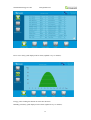


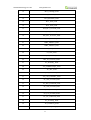
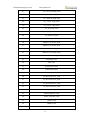
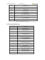


![FRONIUS IG US [42,0410,1089]](http://vs1.manualzilla.com/store/data/005774043_1-689bd6c2a055f0ab88c64924d7fd22c0-150x150.png)