
1
FRONIUS IG 2000 / 3000 / 2500-LV
FRONIUS IG 4000 / 5100 / 4500-LV
42,0410,1089
012010
US Operating instructions
Grid-connected inverters for
photovoltaic systems
Dear Reader
Introduction
Thank you for choosing Fronius - and congratulations on your new, technically highgrade Fronius product! This instruction manual will help you get to know your new
machine. Read the manual carefully and you will soon be familiar with all the many
great features of your new Fronius product. This really is the best way to get the most
out of all the advantages that your machine has to offer.
Please also take special note of the safety rules - and observe them! In this way, you
will help to ensure more safety at your product location. And of course, if you treat your
product carefully, this definitely helps to prolong its enduring quality and reliability - things
which are both essential prerequisites for getting outstanding results.
ud_fr_st_et_00493
012004
Safety rules
DANGER!
WARNING!
CAUTION!
“DANGER!” indicates an imminently hazardous situation which, if not
avoided, will result in death or serious injury. This signal word must be
limited to the most extreme situations. This signal word is not used for
hazards relating to property damage unless there is also a risk of personal
injury appropriate to this level.
“WARNING!” indicates a potentially hazardous situation which, if not
avoided, could result in death or serious injury. This signal word is not used
for hazards relating to property damage unless there is also a risk of personal injury appropriate to this level.
“CAUTION!” indicates a potentially hazardous situation which, if not avoided, may result in minor or moderate injury. It may also be used to draw
attention to unsafe practices that may cause damage to property.
NOTE!
“NOTE!” indicates a situation which implies a risk of impaired results and
damage to the equipment.
Important!
“Important!” indicates practical hints and other particularly useful information. It is not a signal word for a harmful or dangerous situation.
Whenever you see any of the symbols shown above, pay close attention to
the contents of the manual!
General Remarks
This equipment has been manufactured in accordance with the state of the
art and general safety-engineering principles. Nevertheless, incorrect operation or misuse may still endanger
- the life and well-being of the operator or of third parties,
- the equipment and other tangible assets belonging to the owner/operator,
- working efficiently with the equipment.
All persons involved in any way with starting up, servicing and maintaining
the equipment must
- be suitably qualified
- have good knowledge of dealing with electrical installations and
- read this instruction manual thoroughly and follow the instructions to the
letter.
The instruction manual must be kept at the machine location at all times. In
addition to the instruction manual, it is important to comply with both the
generally applicable and local accident prevention and environmental protection regulations.
All the safety instructions and warning signs on the machine itself:
- must be kept in a legible condition
- must not be damaged, must not be removed
- must not be covered, pasted or painted over
I
ud_fr_se_sv_00923
022009
General Remarks
(continued)
For information about where the safety instructions and warning signs are
located on the machine, please refer to the section of your machine’s instruction manual headed “General Remarks”.
Any malfunctions which might impair machine safety must be remedied
immediately before the machine is switched on.
Your safety is at stake!
Utilisation for
Intended Purpose
Only
The machine may only be used for jobs as defined by the “intended purpose”.
Utilisation for any other purpose, or in any other manner, shall be deemed "not
in accordance with the intended purpose". The manufacturer shall not be
liable for any damage resulting from such improper use.
Utilisation in accordance with the “intended purpose” also comprises
- thorough reading of and compliance with all the instructions, safety instructions and warnings given in this manual
- performing all stipulated inspection and servicing work
- installation in accordance with the instruction manual
Where appropriate, the following guidelines should also be applied:
- regulations of the power supply company for input to the grid
- information provided by the manufacturer of the solar modules
Operation or storage of the machine outside the stipulated range is deemed
“not in accordance with the intended use”. The manufacturer shall not be
liable for any damage resulting therefrom.
Ambient
Conditions
Please refer to the technical data in your instruction manual for accurate
information about the permissible ambient conditions.
Qualified Staff
The servicing information provided in this instruction manual is only intended
for qualified staff. An electric shock can be fatal. Please do not carry out any
activities other than those referred to in the documentation. This also applies
even if you are suitably qualified.
All cables and other leads must be firmly attached, undamaged, properly
insulated and adequately dimensioned. Have loose connections, scorched,
damaged or under-dimensioned cables and wires repaired immediately by
an authorised specialist company.
Maintenance and repair may only be carried out by an authorised specialist
company.
There is no guarantee in the case of parts sourced from other suppliers that
these parts have been designed and manufactured to cope with the stresses
and safety requirements that will be placed on them. Use only original spare
parts (this also applies to standard parts).
Do not carry out any alterations, installations or modifications to the machine
without first getting the manufacturer’s permission.
Replace immediately any components that are not in perfect condition.
ud_fr_se_sv_00923
022009
II
Safety Precautions at the Machine Location
Information on
noise emission
values
Ensure when installing machines with cooling-air vents that the cooling air can flow freely
through the air vents without obstruction. Only operate the machine with the degree of
protection specified on the rating plate.
The inverter generates a maximum sound power level of <80 dB(A) (ref. 1pW)
when operating under full load in accordance with IEC 62109-1.
The device is cooled as quietly as possible with the aid of an electronic temperature control system, and depends on the amount of converted power, the
ambient temperature, the level of soiling of the device, etc.
It is not possible to provide a workplace-related emission value for this device
because the actual sound pressure level is heavily influenced by the installation situation, the power quality, the surrounding walls and the properties of the
room in general.
EMC device
classifications
Devices with emission class A:
are only designed for use in an industrial setting
can cause conducted and emitted interference in other areas.
Devices with emission class B:
satisfy the emissions criteria for residential and industrial areas. This
also applies to residential areas in which power is supplied from the
public low-voltage grid.
EMC device classification as per the rating plate or technical specifications
EMC measures
In certain cases, even though a device complies with the standard limit
values for emissions, it may affect the application area for which it was
designed (e.g. when there is sensitive equipment at the same location, or if
the site where the device is installed is close to either radio or television
receivers).
If this is the case, then the operator is obliged to take appropriate action to
rectify the situation.
Mains connection
High-performance devices (> 16 A) can affect the voltage quality on the mains
network because they can feed powerful current into the main supply.
This may affect a number of types of device in terms of:
connection restrictions
criteria with regard to maximum permissible mains impedance *)
criteria with regard to minimum short-circuit power requirement *)
*)
at the interface with the public mains network
see Technical Data
In this case, the plant operator or the person using the device should check
whether or not the device is allowed to be connected, where appropriate
through discussion with the power supply company.
III
ud_fr_se_sv_00923
022009
Electrical Installations
Electrical installations may only be executed in accordance with the relevant
national and regional standards and specifications.
ESD Protective
Measures
Danger of damage to electronic components due to electrostatic discharge.
Take appropriate protective measures when replacing and installing the
components.
Safety Precautions in Normal
Operation
Only operate the machine if all its protective features are fully functional. If
any of the protective features are not fully functional, there is a danger to:
- the life and well-being of the operator or other persons
- the equipment and other tangible assets belonging to the owner/operator
- working efficiently with the equipment.
Have any safety features that are not fully functional repaired by an authorised specialist company before switching the machine on again.
Never bypass or disable safety features.
Safety markings
Equipment with the CE mark fulfils the basic requirements of the Guideline
Governing Low-Voltage and Electromagnetic Compatibility. (More detailed
information about this may be found in the Annex or in the section of your
documentation headed “Technical Data”.)
Disposal
Do not dispose of this device with normal domestic waste!
To comply with the European Directive 2002/96/EC on Waste Electrical and
Electronic Equipment and its implementation as national law, electrical
equipment that has reached the end of its life must be collected separately
and returned to an approved recycling facility Any device that you no longer
require must be returned to our agent, or find out about the approved collection and recycling facilities in your area.
Ignoring this European Directive may have potentially adverse affects on the
environment and your health!
Data security
The user is responsible for backing up data relating to changes made to
factory settings. The manufacturer will not accept liability if personal settings
are deleted.
Copyright
Copyright to this instruction manual remains the property of the
manufacturer.
The text and illustrations are all technically correct at the time of going to
print. The right to make modifications is reserved. The contents of the
instruction manual shall not provide the basis for any claims whatever on the
part of the purchaser. We should be most grateful for your comments if you
have any suggestions for improvement, or can point out to us any mistakes
which you may have found in the manual.
ud_fr_se_sv_00923
022009
IV
Table of Contents
IMPORTANT SAFETY INSTRUCTIONS - SAVE THESE INSTRUCTIONS ................ 4
General ................................................................................................................ 4
Housing ............................................................................................................... 4
Galvanic isolation ................................................................................................ 5
Monitoring the grid ............................................................................................... 5
Repair .................................................................................................................. 5
Solar modules ...................................................................................................... 5
Grid connection ................................................................................................... 6
Standards and Regulations.................................................................................. 6
Product listings and compliance .......................................................................... 6
How a photovoltaic system works ............................................................................ 7
General information ............................................................................................. 7
Your roof is your power generator ........................................................................ 7
Electricity is converted under the roof .................................................................. 7
Operation manual ....................................................................................................... 8
The FRONIUS IG Unit in the PV System................................................................. 8
General information ............................................................................................. 8
Converting DC into AC current ............................................................................ 8
Fully automatic operation management ............................................................... 9
Voltage transformation and galvanic isolation...................................................... 9
Monitoring the grid ............................................................................................... 9
Information for Field adjustable trip points ......................................................... 10
Display function and data communication ......................................................... 10
Your advantage .................................................................................................. 10
Product description......................................................................................................11
The FRONIUS IG Unit ............................................................................................11
How it functions ..................................................................................................11
Startup phase .....................................................................................................11
Overview for housing ......................................................................................... 13
LED for operating status .................................................................................... 15
LED for GFDI status .......................................................................................... 16
Operating scheme ...................................................................................................... 17
The Display............................................................................................................ 17
General information ........................................................................................... 17
Keys and symbols.............................................................................................. 17
Symbols ............................................................................................................. 17
1
Display Navigation ................................................................................................. 18
Display illumination ............................................................................................ 18
Menu level ......................................................................................................... 19
Select display mode .......................................................................................... 19
Scrolling between display functions ................................................................... 20
Display Modes ....................................................................................................... 20
Display mode outline ......................................................................................... 20
Display symbol key ............................................................................................ 21
Display mode "Now" .......................................................................................... 22
Display mode "Day / Year / Total" ...................................................................... 24
The Setup Menu .................................................................................................... 28
List of menu items ............................................................................................. 28
Display mode "Setup" ........................................................................................ 29
Enter the setup menu ........................................................................................ 29
Scroll among menu items .................................................................................. 29
Setting the menu items ...................................................................................... 30
Additional information ................................................................................................. 39
Upgrading the system ........................................................................................ 39
Forced ventilation .............................................................................................. 40
Installation manual ................................................................................................... 41
Installation .................................................................................................................. 42
Installation instructions ...................................................................................... 42
Safety ................................................................................................................ 42
General information ........................................................................................... 42
Choosing the location general ........................................................................... 43
Choosing the location ........................................................................................ 43
Preparing the wall mounting .............................................................................. 44
Connection ................................................................................................................. 45
Safety .................................................................................................................... 45
General .............................................................................................................. 45
Connection to the Solar Modules and to the Utility Grid ........................................ 45
Solar modules .................................................................................................... 45
Grid connection ................................................................................................. 46
Schemes with more than one inverter ............................................................... 48
Connection ........................................................................................................ 49
Connect DC ....................................................................................................... 52
Connect AC ....................................................................................................... 53
Start up Operation ...................................................................................................... 53
Configuring your Inverter ....................................................................................... 53
Factory pre-set configuration ............................................................................. 53
Your personal configuration ............................................................................... 54
2
Ground fault indication ............................................................................................... 54
General .............................................................................................................. 54
LocalNet ..................................................................................................................... 55
System upgrading / plug-in card system ............................................................ 55
Datalogger ......................................................................................................... 55
COM Card ......................................................................................................... 55
Insert plug-in cards ............................................................................................ 56
Configuration ..................................................................................................... 57
Example ............................................................................................................. 57
Status diagnosis and repair ........................................................................................ 58
Service-Codes Displayed ...................................................................................... 58
Service display................................................................................................... 58
Normal operation service codes ........................................................................ 58
System failure .................................................................................................... 59
FRONIUS IG with several power stage sets ...................................................... 59
Class 1 ............................................................................................................... 60
Class 2 ............................................................................................................... 61
Class 3 ............................................................................................................... 62
Class 4 ............................................................................................................... 63
Class 5 ............................................................................................................... 65
Customer service ............................................................................................... 66
Annex ......................................................................................................................... 67
Technical Data ....................................................................................................... 67
General .............................................................................................................. 67
Field adjustable trip points ................................................................................. 68
General .............................................................................................................. 69
Field adjustable trip points ................................................................................. 70
FRONIUS USA limited 10-Year Warranty .............................................................. 71
FRONIUS IG Solar Inverter Models:
FRONIUS IG 2000 / 3000 / 2500 LV / 4000 / 5100 / 4500-LV ........................... 71
Policy and procedure for warranty returns and repairs ...................................... 71
Disposal of obsolete equipment ............................................................................ 72
Recycling ........................................................................................................... 72
Declarations of conformity
Fronius Worldwide
3
IMPORTANT SAFETY INSTRUCTIONS - SAVE THESE INSTRUCTIONS
General
WARNING! Incorrect operation and work performed incorrectly
can cause serious injury & damage! Only qualified staff are
authorized to install your FRONIUS IG and only within the scope of the respective technical regulations. Do not start operation or carry out maintenance work before you have read the
chapter “Safety Regulations“!
This manual contains important instructions for the FRONIUS IG
2000, 3000, 2500-LV, 4000, 5100, 4500-LV that shall be followed
during installation and maintenance of the inverters.
WARNING! These servicing instructions are for use by qualified
personnel only. To reduce the risk of electric shock, do not
perform any servicing other than that specified in the operating
instructions unless you are qualified to do so.
Electrical installations must be made in accordance with the National
Electrical Code, ANSI/NFPA 70, and any other codes and regulations
applicable to the installation site.
To reduce the risk of fire, do not connect multiwire branch circuits to
an AC load center (circuit breaker panel).
Housing
Only qualified installers are authorized to open the connection area.
Do not open the connection area when the inverter is under voltage.
Only Fronius-trained service staff may open the upper portion (power
stage) of the inverter, and only when it is not under voltage.
4
Galvanic
isolation
The design and function of the FRONIUS IG unit offers a maximum
level of safety, both during installation as well as in operation. A complete galvanic isolation between the DC and AC sides is one such
safety feature.
The FRONIUS IG provides galvanic isolation and grid monitoring.
The passive and active measures for the protection of persons and
equipment help ensure safe installation and operation.
Monitoring
the grid
Whenever conditions in the electric grid are inconsistent with standard conditions (for example grid switch-off, interruption, etc.), your
FRONIUS IG unit will immediately stop operating and interrupt the
supply of power into the grid.
Your FRONIUS IG unit determines the grid’s status by:
- monitoring voltage
- monitoring frequency
- monitoring islanding conditions
This scheme prevents dangerous voltages at the AC lines and constitutes an essential contribution towards avoiding hazards for the
maintenance staff.
Repair
Only FRONIUS service staff are authorized to carry out repairs to the
FRONIUS IG unit.
Solar modules
Before connecting the solar modules, you must check whether the
voltage parameters specified in the manufacturer’s data correspond
with the actual parameters.
When checking the voltage reading, please take into account that
solar modules supply a higher open circuit voltage when temperatures are low and sunlight level remains unchanged.
The data sheet of the solar module will tell you the temperature factors applicable for ascertaining the theoretical open-circuit voltage at
14 °F (-10 °C).
If the solar modules exceed an open-circuit voltage of 500 V, regardless of temperature the FRONIUS IG unit might be damaged and all
warranty rights will be voided.
5
Solar modules
(continued)
The FRONIUS IG includes a ground fault detector interruptor (GFDI)
according to UL 1741. This device measures the ground current of
the PV array and prevents the inverter from feeding the grid in case
of a ground fault.
Grid connection
Only appropriately licensed contractors are authorized to connect
your FRONIUS IG to the grid. Consult your local authorities for specific requirements.
Before connecting the FRONIUS IG to the grid, permission for the
connection must be granted by the utility company.
Standards
and Regulations
Your FRONIUS IG unit complies with the requirements for "Inverters,
converters and controllers for use in independent power systems"
UL1741-2005 and IEEE 1547 standards. The ground-fault detection
and interruption is in compliance with NEC 690 building code requirements.
Product listings and
compliance
The respective conformity declarations can be found in the appendix
to these operating instructions.
6
How a photovoltaic system works
string
mod. 2
mod. n
mod. 1
-
-
mod. 2
string 3
string 2
string 1
mod. 1
+
total string voltage
module 1
module 2
+
module 3
Power output and voltage are increased by combining a number of
solar cells. If solar modules are connected in series like on a string,
both the output power as well as the voltage will increase.
voltage
Your roof is
your power
generator
voltage
The energy from worldwide sunlight amounts to a total of about
1,540,000,000,000,000,000 kWh/year (1,540 Peta kWh/year). This is
15,000 times as much as the electricity consumption worldwide. We
congratulate you on your decision to actively use world’s biggest
energy resource. The word "photovoltaic" comes from the driving
force behind this technology, which is light. When light strikes photovoltaic cells, a voltage and current is created.
voltage
General information
mod. n
total array current =
current string 1 + 2, ... n
In a parallel connection of several such strings the output power and
the output current will increase, while the voltage will remain unchanged (see right picture). The combination of all solar modules connected in series and parallel is called a solar array.
Electricity is
converted
under the
roof
The direct current generated in the solar modules can only be fed
into the grid or used in your home after having been transformed by
an inverter.
This is the basic purpose of your FRONIUS IG unit.
7
Operation manual
The FRONIUS IG Unit in the PV System
General information
The FRONIUS IG is the latest generation of solar inverter. It is the
highly complex link between solar modules and the grid.
As such it is responsible for a number of high-level tasks. The following diagram gives a graphical overview as to where the FRONIUS
IG is placed in the PV system.
FRONIUS IG
Main AC
Load
Center
PV array
Converting
DC into AC
current
Energymeter
The FRONIUS IG unit transforms the direct current generated by the
solar modules into alternating current. This alternating current is fed
into your home system or into the public grid and synchronized with
the voltage that is used there. The FRONIUS IG has been designed
exclusively for use in grid connected photovoltaic systems. It cannot
generate electric power independent from the grid.
8
Fully automatic operation
management
The FRONIUS IG is fully automatic. Starting at sunrise, as soon as
the solar modules generate enough power, the automatic control unit
starts monitoring voltage and frequency. As soon as there is a sufficient level of insolation, your solar inverter starts feeding energy to
the grid. A few Watts of solar power output are sufficient to achieve
this.
The control system of the FRONIUS IG unit ensures that the maximum possible power output is drawn from the solar modules at all
times.
This function is called MPPT (Maximum Power Point Tracking). It
operates with extremely high precision. As dusk starts and there is
no longer sufficient energy available to feed power into the grid, the
FRONIUS IG unit shuts down the grid connection completely and
stops operating. All settings and data recorded are saved.
Voltage transformation
and galvanic
isolation
The FRONIUS IG has been designed for use with solar modules of a
wide range of input voltages. This allows the use of the greatest
variety of types of solar modules. Important notice: the parameters
indicated for maximum DC voltage (total voltage of the solar modules
connected) must at no time be exceeded!
By its design and operation, the FRONIUS IG offers maximum safety
during installation as well as in operation.
The FRONIUS IG is equipped with an HF-transformer (HF = high
frequency) that ensures galvanic isolation between the DC side and
the grid. In addition, the HF principle results in a drastic reduction of
the transformer’s size, which means that it requires less space and
has considerably less weight. The FRONIUS IG unit achieves a high
degree of efficiency due to its innovative circuit schemes.
Monitoring
the grid
The FRONIUS IG unit monitors the grid. This responsibility comprises all measures necessary for the protection of persons and machines in case of a power blackout or other grid loss.
The FRONIUS IG unit is programmed to stop operation immediately
and stop supplying power whenever conditions in the grid deviate
from standard conditions (for example, when power is switched off or
in case of any other kind of interruption).
9
Monitoring
the grid
(continued)
There are several ways the FRONIUS IG unit can identify a gridcutoff, by monitoring:
- voltage
- frequency
- islanding conditions
Information
for Field
adjustable
trip points
The FRONIUS IG unit is provided with field adjustable trip points. For
further information please contact Fronius technical support E-Mail:
[email protected].
Display function and data
communication
The FRONIUS IG unit comes standard with a display that has been
designed to enable quick and easy access to the most important
data in your PV system.
The FRONIUS IG is equipped with a basic logging function to monitor minimum and maximum data on a daily and a cumulative basis.
There is also an option to allow the reading of the following weather
data on the display:
- two different temperature readings (for example, temperature at
the solar modules as well as the outside temperature)
- irradiance
In addition to the functions installed in the FRONIUS IG unit, a wide
choice of data communication products allows for many possibilities
of recording and visualizing data. The respective components required to upgrade the system are easy to install.
Your advantage
With each additional parameter, that is controlled directly by the
inverter, installation becomes easier and less costly because no
additional peripheral equipment will be required. Based on our experience and the use of the most innovative technologies, the FRONIUS IG unit is able to manage all system parameters simultaneously.
In addition, the FRONIUS IG unit complies with a wide range of
requirements established for the safety of people and other household appliances, as well for its own protection.
Some of these requirements are:
- ability to monitor the grid
- the quality of the electricity supplied
- immunity from outside disturbance and interference (for example,
from mobile telephones).
10
Product description
The FRONIUS IG Unit
How it functions
The FRONIUS IG unit is designed for fully automatic operation. No
manual control is necessary for feeding the power it generates into
the grid.
The FRONIUS IG unit starts operating automatically as soon as the
power output of the solar modules is sufficient after sunrise.
During its operation the FRONIUS IG unit optimizes the voltage of
the solar modules for maximum power output.
- the optimal voltage for any particular solar module is called MPP
voltage (MPP = maximum power point)
- maintaining the exact MPP voltage guarantees an optimal level of
efficiency for your modules at any time (MPP-tracking).
As soon as dusk begins there is no longer sufficient energy available
to feed into the grid. The FRONIUS IG unit fully shuts off the grid
connection at this time.
- during the night the FRONIUS IG unit draws less than 150 mW
from the grid
- the data and parameters are saved
- it is also possible to shut the unit off manually
Startup phase
After switching on automatically, the FRONIUS IG unit goes through
a self-test, followed by an extensive test of the grid. This test takes
five minutes. During the startup sequence the LED illumination is
yellow.
(1) LCD test
- all display elements light up for about one second
11
Startup phase
(continued)
(2) TEST
- self test of important components of the FRONIUS IG unit
- The FRONIUS IG unit goes through a master check list for
several seconds
- the display says "TEST" and indicates the respective component which is being tested (for example "LED")
(3) Synchronisation with grid
- "WAITPS" is displayed: The
FRONIUS IG is waiting for
all power supplies in the
network to be on stand-by.
This procedure takes place
dependent on the DCvoltage.
- The screen displays "SYNCAC"
- "SYNCAC" is displayed subsequently.
(4) Startup test
- Before the FRONIUS IG unit starts feeding energy into the grid,
the conditions of the grid are tested in detail in accordance with
regulations.
- the screen displays "STARTUP"
The startup test takes five minutes. The time elapsed is indicated by
a bar shrinking from the top down.
Whenever two scale divisions stop flashing and disappear,
1/10 of the total duration of the test is over
(5) Operation of feeding energy into the grid
- After conclusion of the tests, the FRONIUS IG unit starts feeding energy into the grid.
- The LED lights up green, and the FRONIUS IG unit starts operating
12
Overview for
housing
(1) Knockout for 1/2 in. / 3/4 in. conduit fitting (DC-cables)
(2) Knockout for 1/2 in. / 3/4 in. conduit fitting (DC-cables)
(3) Knockout for 1/2 in. / 3/4 in. conduit fitting (AC-cables)
(4) Knockout for 1/2 in. / 3/4 in. conduit fitting (DC-cables)
(5) Knockout for grounding electrode (may be required by local
authorities)
(6) Knockout for 1/2 in. / 3/4 in. conduit fitting (DatCom cables)
(7) LCD
(8) LED for operating status
(9) LED for GFDI status
(10) Knockout for 1/2 in. / 3/4 in. conduit fitting (DatCom cables)
(11) Knockout for 1/2 in. / 3/4 in. conduit fitting (DatCom cables)
(12) Air vents - Exhaust
(13) Air vents - Intake
(1)
(2)
(3)
(4)
(5)
(6) (7) (8) (9)
13
(10) (11) (12)
(13)
Overview for
housing
(Continued)
WARNING! Hazard due to supply voltage and DC-voltage from
the solar modules. Only qualified electrical professionals are
authorized to open the connection area of the FRONIUS IG and
only when it is not under voltage.
(14) Connection area - to be opened only by qualified electrical professionals
(15) AC-disconnect
(16) DC-disconnect
(17) GFDI fuse
(18) Menu buttons
(19) Operating status LED
(20) GFDI LED
(14)
(15) (16) (17) (18)
14
(19)
(20)
LED for operating status
LED for
GFDI
status
LED for
operating
status
Depending on the operating status, the LED assumes different colors
(1) LED lights up green:
- a green light starts as soon as the FRONIUS IG unit has completed the startup phase, and stays green as long as the operation of feeding power into the grid continues
- it indicates faultless operation of the photovoltaic equipment
(2) LED flashes green:
- as long as the photovoltaic equipment is operating without fault
- an additional message is displayed on the screen
NOTE! A service code may appear, for example, if there is a
fault in the DatCom system. That does not affect the function
of the FRONIUS IG. However, it is recommended that the fault
is remedied as soon as possible.
The FRONIUS IG shows a status message.
If a service code (e.g., "504", in Section "Status diagnosis and repair") is shown, rectify the relevant condition and acknowledge the
message by pressing the "Enter" button.
(3) LED lights up orange:
- The FRONUS IG unit will enter the automatic startup-phase, as
soon as the photovoltaic modules yield sufficient power output
15
LED for operating status
(continued)
(4) LED flashes orange:
- when a warning is displayed on the screen
- or the FRONIUS IG unit has been set to standby operation in
the setup menu (manual shutoff of operation)
- the next day, operation will resume automatically
- during the time the orange LED is flashing, the operation can
be resumed manually at any time (see chapter "Setup Menu")
(5) LED lights up red:
- general status: the respective service code is displayed on the
screen
A list of all service codes, the corresponding status information,
their status causes and repair measures can be found in the chapter "Status Diagnosis and Repair" of the installation and service
manual.
(6) LED remains dark:
- there is no connection to the solar modules
- no power output from modules due to darkness
LED for GFDI
status
(1) LED remains dark:
- there is no ground fault in the PV system
- the system is working properly
(2) LED lights up red:
- ground fault is detected and fuse is blown
- the inverter does not feed energy to the grid
- the ground fault needs to be removed and the fuse needs to be
changed (see chapter "Ground fault indication" in the installation
manual)
16
Operating scheme
The Display
General information
The FRONIUS IG unit is pre-configured to be ready for operation.
Therefore it is not necessary to make any adjustments for it to operate and feed power into the grid.
(A) and (B) keys:
- scrolling
Keys and
symbols
(A)
Symbols
(B)
(C)
(C) key:
- switching to the menu level
("Menu") or exit from the setup
menu ("Esc")
"Enter" Key (D):
- confirming a choice
(D)
(2)
(12) (11) (10)
(9)
(5)
(7)
(8)
(6)
(4)
(1)
(3)
(1) symbols for keys (A) through (D)
(2) symbols for the display modes "Now" through "Setup"
(3) area for data display ... for displaying the data value measured
(4) area for unit display ... for displaying the applicable measuring
unit
17
Symbols
(continued)
(5) output bar ... indicates the power output fed into the grid at a
given moment - independent from the display mode chosen.
The screen displays % of the maximum possible output power
of your solar inverter
(6)
... appears with AC data readings that are directly related
to the grid
(7)
... appears with data readings that are directly related to
the solar modules
(8)
... appears with data readings that are related directly to the
FRONIUS IG unit
(9)
... appears with data readings that are related to environmental conditions, like sunlight insolation and temperature (optional)
(10)
...appears with data readings that are transmitted by the
consumption sensor (optional)
(11) Max ... indicates the maximum value within the period of observation (depending on the display mode chosen)
(12) Min ... indicates the minimum value within the period of observation (depending on the mode of display chosen)
Important! The Min. and Max. values may not correspond to the
absolute extreme values, as the measured data is recorded at two
second intervals.
Display Navigation
Display illumination
Press any key to activate the display backlight. If no key is pressed
for 30 seconds, the display backlight stops. The setup menu also
offers a choice between permanently alit or permanently dark display.
18
Menu level
From the menu level you can
enter the display mode or the
setup menu.
Access the top level menu by
pressing the (C) key.
(C)
(C)
Select display mode
- the screen displays "Menu"
- the display is operating in the
top level menu
(1) (2) (3) (4)
(A)
(A)
(B)
(D)
(B)
Select from the available modes:
Instantaneous data, daily data,
annual data, or total data over
the life of the FRONIUS IG.
- select the desired display
mode (1) to (4) by pressing
keys (A) or (B)
- enter the display mode selected by pressing the key
"Enter" (D)
NOTE! The menu item
"Year" is only supported
when the Datalogger is
connected.
(D)
19
Scrolling
between
display functions
(A)
(B)
(A)
(A)
(B)
(B)
- select the desired display mode (see above)
- scroll between the display functions available with keys (A) or (B)
Display Modes
Display mode
outline
The following display modes are available:
display mode "Now" ...shows present data
display mode "Day" ... shows data for the current day
display mode "Year" ...shows data for current calendar year - only
available in combination with Datalogger
display mode "Total" ... shows data since your FRONIUS IG unit
first started operating
20
Display symbol key
The following table contains a brief list of the display readings available.
Display readings without an asterisk are shown even if no Datalogger
or Sensor box is connected to the FRONIUS IG.
Mode "Now"
output power
(W)
voltage
(V)
output current
(A)
grid frequency
(Hz)
module voltage
(V)
module current
(A)
* module temperature
(°F; also °C)
GFDI status
*
*
*
*
output reading of consumption
meter
(W)
ambient temperature
(°F; also °C)
irradiance
(W/m²)
time
(HH:MM)
Mode "Day" / "Year" / "Total"
energy supplied
(kWh / MWh)
yield
(set applicable currency)
CO2-reduction
(lb / t)
maximum power output
(W)
grid voltage (maximum)
(V)
grid voltage (minimum)
(V)
array voltage (maximum)
(V)
* energy as read by consumption meter
(kWh / MWh)
* module temperature (max.)
(°F; alternat. also °C)
*
*
*
*
module temperature (min.)
(°F; also °C)
ambient temperature (max.)
(°F; alternat. also °C)
ambient temperature (min.)
(°F; alternat. also °C)
irradiance (max.)
(W/m²)
operating hours of FRONIUS
IG unit
(HH:MM)
* optional - when the DatCom component for the required option is
not available, the message "N.A." (not available) is displayed.
21
Display mode
"Now"
Displays present readings
- select display mode "Now" (see the chapter "The Display")
- the first display reading of the display mode "Now" appears
AC power supplied ...power
supplied to grid at the particular moment (Watts)
(A)
-
(B)
-
for the next item press key
(B)
to scroll back press key (A)
AC grid voltage
(Volts)
AC current supplied .. current supplied to the grid at
the particular moment (Amperes)
grid frequency
(Hertz)
DC array voltage... voltage
of the solar array at the moment of data display (Volts)
DC array current ... current
supplied by solar array at the
moment of data display (Amperes)
*
22
DC module temperature ...
temperature at solar modules
(°F; can also be set for °C;
this corresponds to temperature sensor No.1; Sensor
Box and temperature sensor
required)
Display mode
"Now"
(continued)
GFDI status ... if there is no
ground fault in the system
"OK GFDI" is displayed
*
power drawn from the grid
... present consumption
(Watts; Sensor Box and load
sensor required)
*
ambient temperature (°F;
can also be set for °C in
setup menu; this corresponds to temperature sensor
No.2; Sensor Box and temperature sensor required)
*
irradiance ... the sunlight’s
power per square meter
(Watts/m²; Sensor Box and
irradiance sensor required)
*
time of the day (HH:MM,
Datalogger required)
* optional - if the DatCom component for the required options are not
available, the message "N.A." (not available) is displayed.
23
Display mode
"Day / Year /
Total"
Display mode “Day“ ... shows readings for the current day
- energy supplied (kWh)
- yield (currency can be selected)
- CO2 reduction (lb)
- maximum power supplied (Watts)
- maximum grid voltage (Volts)
- minimum grid voltage (Volts)
- maximum module voltage (Volts)
- energy drawn from the grid (kWh)*
- maximum module temperature (°F; alternatively °C)*
- minimum module temperature (°F; alternatively °C)*
- maximum ambient temperature (°F; alternatively °C)*
- minimum ambient temperature (°F; alternatively °C)*
- maximum irradiance (W/m2)*
- operating hours for FRONIUS IG unit
* optional - if the DatCom component for the required option is not
available, the message "N.A." (not available) is displayed.
Important! For the FRONIUS IG unit, the day begins when it switches on. If the DC supply line is disconnected, the parameters will be
re-set after repeating the start-up.
This does not apply if a Datalogger is connected to the FRONIUS IG.
If the Datalogger is available, the display values listed always apply
for the whole day, beginning at 0:00am, ending at 0:00am the following day.
Display mode "Year" ...shows readings for the current calendar year,
from January 1st (only in conjunction with Datalogger)
Display mode "Total" ...shows readings since original start of operation of the FRONIUS IG unit.
- select display mode "Day" / "Year" / "Total" (chapter "The Display")
- the first display function of the display mode selected will appear
24
Display mode
"Day / Year /
Total"
(continued)
Energy supplied ... energy
supplied during monitored
period (kWh / MWh)
(A)
(B)
Due to the variety of different monitoring systems, there can be deviations between the readings of other metering instruments as compared to the readings from the FRONIUS IG. For determining the
energy supplied to the grid only the readings of the calibrated meter
supplied by the electric utility company are relevant.
-
press (B) for next item
to scroll back press (A)
Yield ... money earned during monitored period (set
currency and price per kWh
in setup menu)
Important! As was the case for the energy supplied, readings may
differ from those of other instruments.
The chapter “The Setup Menu“ tells how to set currency and rate
applicable for invoicing. The factory setting is 0.14 US-Dollar (USD)/
kWh.
CO2-reduction ... CO2 emissions avoided during monitored period (lb/t)
The CO2 meter gives an indication of CO2 emissions (in lb/t) that
would be released during the generation of the same amount of
electricity in a combustion power plant. This is set for 1.3 lb/kWh in
the factory.
Maximum output power ..
highest output power of the
FRONIUS IG during observation period (W)
Maximum grid voltage ...
highest reading of grid voltage (V) during observation
period
25
Display mode
"Day / Year /
Total"
(continued)
Minimum grid voltage...
lowest reading of grid voltage
(V) during observation period
Maximum array voltage...
highest reading of array
voltage (V) during observation period
*
Energy consumption meter
reading
energy consumed during
observation period (kWh /
MWh; Sensor Box and consumption sensor required)
*
maximum module temperature ... highest temperature
reading at solar modules
during observation period
(°F; can also be set for °C in
setup menu; temperature
sensor No. 1; Sensor Box
required)
*
minimum module
temperature...lowest temperature reading at solar modules during observation period
(°F; can also be set for °C in
setup menu; temperature
sensor No. 1; Sensor Box
required)
*
maximum ambient temperature ... highest ambient
temperature reading during
observation period (°F; can
also be set for °C in setup
menu; temperature sensor
No. 2; Sensor Box required)
NOTE! Fit the temperature probe near the solar
module.
26
Display mode
"Day / Year /
Total"
(continued)
*
minimum ambient
temperature...lowest ambient temperature reading
during observation period
(°F; can also be set for °C in
setup menu; temperature
sensor No2; Sensor Box
required)
*
maximum irradiance...
highest irradiance during
observation period (W/m²;
Sensor Box and reference
cell required)
operating hours ... duration
of operation of FRONIUS IG
unit (HH:MM)
Duration of operation is shown in hours and minutes up to 999 h and
59 min (display: "999:59"). From then on only full hours are displayed.
Although the FRONIUS IG unit does not operate during the night, all
sensor data are recorded around the clock.
27
The Setup Menu
List of menu
items
The diagram below shows the menu of adjustable parameters
Standby
Contrast
LightMode
Cash
IG-NR
DatCom
Time
State_PS
Version
Enter
0 ... 7
AUTO
currency
ON
OFF
rate / kWh
00 ... 99
OKCom Error SIGCD_TEST PDC_RST
Date
Time
Status display - power stage sets
MainCtrl
28
PS00
PS01
Display mode
"Setup"
The setup menu allows easy readjustment of the FRONIUS IG’s
preset parameters to your needs.
Enter the
setup menu
(1) (2) (3) (4) (5)
(A)
(A)
(B)
- move to the menu level (see
the chapter "Navigating in the
Display")
- select "Setup" mode (5) with
(A) or (B) keys
- enter the mode "Setup" (5) by
pressing the "Enter" key (D)
(D)
(B)
- "Standby" (the first item on the
menu) is displayed
(D)
Scroll among
menu items
(A)
(B)
(A)
(A)
(B)
(B)
- select the desired display mode (see above)
- scroll with (A) or (B) keys among the menu items available
29
Setting the
menu items
- "Standby" ...activate/deactivate the standby operation by
pressing the “Enter“ key
(D)
The menu item "Standby" allows manual activation of the standby
operation of the FRONIUS IG unit. The standby mode is helpful
when troubleshooting or adding/removing system components.
During standby operation the electronic system of the power stage is
switched off. No power is fed into the grid. The LED flashes orange.
The following message flashes intermittently on the screen:
"STANDBY" "ENTER"
- The orange flashing LED stops at dusk.
- After the subsequent sunrise, the power supply operation into the
grid is resumed automatically (after termination of the startup phase the LED is illuminated green)
- grid supply operation can be resumed at any time whenever the
LED is flashing orange (deactivate "standby")
To activate standby:
- When the LED is green: activate "standby" (manual shutoff of operation supplying power into the grid):
- press "Enter" key (D)
To deactivate standby:
- When the LED is flashing orange: deactivate "standby" (resuming
operation supplying power into the grid)
- press "Enter" key (D)
30
- "Contrast" ... set contrast on
LCD display
(C)
(D)
(D)
- select from settings "0" to
"7" - press key (A) or (B):
- enter "Contrast": press "Enter"
key (D)
Since contrast depends on temperature, it may be necessary to
adjust the menu item "Contrast"
when ambient conditions change.
Settings for minimum possible
contrast (0) up to maximum possible contrast (7):
(C)
(D)
...
(A)
- maintain previous setting:
press "Esc" key (C)
(B)
(C)
- accept: press "Enter" key (D)
(D)
- "Menu Mode" ... cannot be
selected
(C)
31
- "Light Mode" ... pre-setting of
display illumination
(C)
- to enter "Light Mode": press
"Enter" key (D)
(D)
(D) - To switch between settings
Auto 1., On 2. and Off 3.
- press keys (A) or (B):
(C)
1.The display illumination will
stop 30 seconds after the last
time a key has been pressed
- accept: press "Enter" key (D)
- maintain previous setting:
press "Esc" key (C)
(D)
(A)
(B)
(A)
(C)
2.The display will continue to
remain illuminated whenever
power is supplied to the grid
- accept: press "Enter" key (D)
- maintain previous setting:
press "Esc" key (C)
(D)
(B)
(C)
3.The display illumination will be
permanently off:
- accept: press "Enter" key (D)
- maintain previous setting:
press "Esc" key (C)
(D)
Important! These instructions are only applicable for the display
background illumination. The LCD will still remain on during operation. Its energy consumption is less than one mW (1/1000 W).
(C)
- "Cash" ... setting of currency
and rate for invoicing the energy supplied
- enter "Cash" by pressing "Enter" key (D)
(D)
(D)
1
2
32
The name of the currency units can be changed. For example, here you see the units
changed from the default US Dollars (USD) to Canadian Dollars (CAD).
1
(D)
2
(A)
(B)
(C)
(D)
...
...
(A)
(B)
(C)
(D)
(D)
1. Enter currency (factory pre-set
for US-Dollars - USD)
- first digit starts flashing
- select a character for the first
digit by pressing key (A) or (B)
- confirm by pressing "Enter"
key (D)
- next digit starts flashing
- follow same procedure as
described above for subsequent digits
- accept the currency selected
by pressing "Enter" key (D)
- to maintain previous setting,
press "Esc" key (C)
2.Enter rate per kWh according
currency selected (preset rate:
0.14 USD/kWh)
(D)
(A)
(B)
(D)
...
...
(D)
(C)
(A)
(A)
(B)
(B)
(C)
(C)
- first digit starts flashing
- select a figure for the first digit
by pressing (A) or (B) keys
- confirm by pressing "Enter"
key (D)
- next digit starts flashing
- for subsequent digits, follow
same procedure as described
above for first digit
(D)
(D)
NOTE! numbers between
000.1 and 99.99 may be
selected
33
To move decimal point:
- decimal point starts flashing
- move the decimal point to the
position desired by pressing
(A) or (B) keys
- accept the rate set by pressing
"Enter" key (D)
- to maintain previous setting,
press "Esc" key (C)
(C)
(D)
(D)
- "IG-NR" ...Setting the number
(address) of the FRONIUS IG
unit in a setup comprising
multiple FRONIUS IG units
linked together
- enter "IG-NR" by pressing the
"Enter" key (D)
enter address (00 ... 99)
(factory setting: 01)
(A)
(B)
(C)
(D)
(D)
- first digit starts flashing
- select a figure for the first digit
by pressing (A) or (B) keys
- confirm with "Enter" key (D)
- subsequent digit starts flashing
- for second digit follow procedure as described above for first
digit
(A)
(B)
(D)
- accept the IG-No. selected: press "Enter" key (D)
- maintain previous setting: press "Esc" key (C)
NOTE! Allocate a different address to each FRONIUS IG
when connecting several FRONIUS IGs into a data communication network using COM Cards and a Datalogger.
It is important to give each FRONIUS IG its own address so that the
Datalogger can differentiate between the individual inverters. If two
FRONIUS IGs are in the system with the same address, they cannot
communicate with the Datalogger. In this case the service code 504
is shown on the display and the LED flashes green. Set the address
on the other FRONIUS IG showing the state message 504.
Important! If your inverters have the same address this only will
affect data communication and not the FRONIUS IG’s power output.
34
(D)
(C)
(D)
(C)
(C)
If a successful data link has been
set up then "OKCOM" is displayed.
35
"Error" is displayed if DatCom is
not installed or the data link is
not functioning correctly.
NOTE! The menu item
"Time" is only supported
when the FRONIUS Datalogger is connected.
(C)
(D)
- "Time" ... setting of date and
time
- enter "Time" by pressing "Enter" key (D)
(D)
(A)
(B)
(C)
(D)
(C)
(D)
(D)
(A)
(B)
1.Enter date (e.g.: 28.01.2006)
- Date format is day, month, year
- first digit starts flashing
- select a character for the first
digit by pressing (A) or (B)
keys
- confirm by pressing "Enter" key
(D)
- next digit starts flashing
- follow the same procedure as
described above for subsequent digits
- accept the date selected by
pressing "Enter" key (D)
- to maintain previous setting,
press "Esc" key (C)
(D)
(A)
(B)
(C)
(D)
(D)
(A)
(B)
(C)
(D)
36
2.Enter time (e.g.: 15:47)
- US military time (24 hour clock)
- first digit starts flashing
- select a figure for the first digit
by pressing (A) or (B) keys
- confirm by pressing "Enter" key
(D)
- next digit starts flashing
- for subsequent digits, follow
the same procedure as described above for first digit
- accept the time set by pressing
"Enter" key (D)
- to maintain previous setting,
press "Esc" key (C)
- "STATE_PS" ... Status display
of power stage sets
- Press "Enter key" (D)
- In this case, for example, the
first power stage set (PS00) is
on "Standby"
- "Standby" means no electricity
is being fed into the public
mains
- Press "Enter" key (D)
(D)
(D)
(D)
- Display of the most recently
stored service code (e.g. "State
406")
(D)
Important! The most recently
stored service code and the
display "State Last" appear alternately.
Alternately
(C)
(C)
(B)
- Press "Esc" key (C)
- The display for the first power
stage set (PS00) re-appears
- Change over to the second
power stage set by pressing
key (B)
(B)
- In this case for example the
second power stage set
(PS01) is on "Run"
- "Run" means intact delivery of
electricity to the public mains
- Press "Enter" key (D)
(D)
(D)
- Display of the most recently
stored service code (e.g. "State----")
Alternately
Important! The most recently
stored service code and the
display "State Last" appear alternately.
2x
(C)
- Press "Esc" key (C) twice
NOTE! State 306 (Power Low) and 307 (DC-Low) appear
naturally every morning and evening due to low solar irradiance. These status messages are not the result of a fault.
37
- "Version" displays version
number of the IG control unit
and the power stage
(D) - To switch between displays
MAINCTRL1., PS00 2. - press
key (A) or (B)
(C)
(D)
display
version number
(A)
- enter "Version" by pressing
"Enter" key (D)
1.For displaying version number
of the IG control unit : press
"Enter" key (D)
- exit by pressing "Esc" key
(C)
- to switch into display of serial
number for the IG control unit:
press "(A) or (B)" keys
- exit with "Esc" key (C)
(C)
(A)
(B)
(B)
display
serial number
(C)
(C)
(D)
display
version number
(A)
(B)
(C)
display
serial number
(C)
38
2.To display version number of
power stage, press key "Enter
(D)" - exit with key "Esc (C)"
- to switch into display of serial
number of the power stage,
press keys "(A) or (B)" - exit
with key "Esc (C)"
Additional information
Upgrading
the system
The FRONIUS IG unit is prepared for a whole series of system upgrades, such as:
- Communication between FRONIUS IG and DatCom units
- Dataloggers (for recording and managing your photovoltaic system
data via personal computer), including Datalogger and modem
connection
- Interface Card Easy sends all relevant working parameters in a
well defined RS-232 protocol
- Personal Display FRONIUS IG
- Various large displays (FRONIUS IG Public Display)
- Sensors (temperature sensor / irradiance / electricity consumption
meter / ...)
For more information on Fronius communication products, please
refer to the individual product literature, www.fronius-usa.com.
Some system upgrades are offered as plug-in cards, similar to those
on your personal computer.
Other system upgrades are offered in external housings
For unlimited system upgradeability, Fronius has developed the
LocalNet. LocalNet is a data network that allows linking multiple
FRONIUS IG units with data communication components.
LocalNet is a bus system. One single cable is sufficient to allow
communication between one or several FRONIUS IG units with all
system upgrade elements. This reduces the cable requirement to a
minimum.
39
Upgrading
the system
(continued)
Please see further information in the chapter "LocalNet" of the installation and service manual.
Forced ventilation
The FRONIUS IG unit is equipped with a temperature controlled,
variable speed fan that provides the following features:
- more compact housing - as a result of smaller heat sinks
- components are better cooled - efficiency increases / longer life
- least possible energy consumption / noise level, due to the variable
speed control and ball bearing support
- should there be insufficient heat dissipation in spite of the fan operating at maximum speed (for example inadequate heat transfer
away from the heat sinks) the power will be derated for protection
of the FRONIUS IG unit.
- derating the power reduces the output of the FRONIUS IG unit for
a short period sufficient to ensure that the temperature will not
exceed the admissible limit.
- your FRONIUS IG unit will remain ready for operation as long as
possible without any interruption.
40
Installation manual
41
Installation
Installation
instructions
Safety
General information
These installation instructions serve as a manual for qualified electrical
professionals and detail the installation, initial operation, status diagnosis
and repair processes. It is in your interest to read the operating instructions thoroughly and follow the instructions it contains. In so doing you will
avoid malfunctions resulting from incorrect operation.
WARNING! Work performed incorrectly can cause serious injury
and damage.
- Read the installation instructions carefully before installing the
FRONIUS IG.
- Only a qualified electrical professional is authorized to carry out
the installation of the FRONIUS IG.
Your FRONIUS IG is the latest generation of solar inverter. It is the highly
complex link between your solar modules and the grid. As such, it is in
charge of a number of highly technical tasks. The following diagram
should give you a brief overview of a PV system including a FRONIUS IG.
FRONIUS IG
Main AC
Load
Center
PV-array
42
Energymeter
Choosing the
location general
To get the most out of your FRONUS IG unit, observe the following rules:
Choosing the
location
- during certain operation phases the FRONIUS IG unit may produce a
slight noise. For this reason it should not be installed in an occupied
living area
- the FRONIUS IG unit is not to be set up in areas with large amounts of
dust. If unavoidable, place the FRONIUS IG in an appropriately rated
and ventilated box.
- the FRONIUS IG unit is not to be set up in areas with large amount of
conducting dust particles (for example iron filings)
- the FRONIUS IG unit is to be installed at a height that keeps the display
slightly below eye level for best possible readability of the display.
- NEMA 3R protection means that the FRONIUS IG can be exposed to
moisture. However, we recommend that direct moisture be avoided, if
possible.
- In spite of the NEMA 3R protection system, the FRONIUS IG should not
be exposed to direct sunlight, as this could result in temperature derating.
- Limit grid impedance by using an appropriately-sized AC conductor
between the FRONIUS IG unit and the in-house distribution panel. The
AC conductor cable resistance between the FRONIUS IG unit and the
house distribution panel should not exceed 0.5 Ohm. This can be achieved by using the following cable-sizes (according to NEC handbook,
chapter 9, table 8):
- AWG 10: maximum 200 ft. (60 m)
- AWG 12: maximum 126 ft. (38 m)
- Only install it on a solid vertical wall at a minimum of 3 ft. (0.9 m) above
the ground and to a maximum of 6.5 ft. (2 m)
- The ambient temperature should not be below -4 °F (-20 °C) or over
122 °F (50 °C).
- No objects are to be located within a distance of 6 in. around the air
vents on both sides of the FRONIUS IG unit.
- Keep a distance of 8 in. minimum. For optimal airflow and cooling efficiency in hot climates Fronius recommends a distance of 10 - 12 in.
between each inverter or anything to the right or left of the inverter such
as walls or DC and AC disconnects.
- The air flow direction within the inverter is from left to right (cold air
intake on left, hot air exit on right).
- When installing the FRONIUS IG unit in a switch panel cabinet (or
similar closed environment) it is necessary to make sure that the hot air
that develops will be discharged by forced ventilation.
43
Preparing the
wall mounting
The following describes how the FRONIUS IG is mounted to the wall. As
your FRONIUS IG is delivered, the mounting plate is fixed to the inverter
by two screws on the bottom of the FRONIUS IG.
For mounting the inverter to the wall proceed as follows:
- Loosen the screws (1) on the bottom of the inverter and remove the
mounting plate (2)
- Fix the mounting plate (2) to the wall using four suitable screw anchors
(3) and screws (4)
(2)
(4) (3)
(4)
(3)
(4) (3)
(4)
Important! Due to the variety of
screw anchors (3) and screws (4)
available for the various types of
wall surfaces, these are not included.
(3)
(1)
In most cases, you should use 1/4 in. or 5/16 in. stainless steel or aluminium screws capable of supporting 26 lbs (FRONIUS IG 2000, 3000 and
2500-LV) or 42 lbs (FRONIUS IG 4000, 5100 and 4500-LV) of inverter
weight. Triangulate the positions of these on the mounting plate using the
pre-drilled holes when possible. Three vertically aligned holes for single
stud mounting will suit most installations.
CAUTION! The FRONIUS IG may become dislodged and fall from
the mounting plate if the unit is not fixed to the mounting plate using
the two screws at the bottom (that were removed at the beginning).
NOTE! If you modify the FRONIUS IG enclosure with custom
openings you will be required to return the unit for repair in the
event of a warranty-related issue rather than doing an inverter
exchange. Knockouts for grounding electrode may be required by
local authorities.
- Slide the FRONIUS IG from above so that the unit may hang from the
top of the mounting plate (2)
- Attach the FRONIUS IG to the bottom of the mounting plate (2) by
using the screws (1) that were removed before
44
Connection
Safety
General
WARNING! Hazard due to supply voltage and DC-voltage from the
solar modules. Only qualified electrical professionals are authorized
to open the connection area of the FRONIUS IG and only provided
that it is not under voltage.
WARNING! An electric shock can be fatal. Inadequately sized
electrical components can cause serious injuries to persons and
damage to (or loss of) property.
- Electrical installations must be in accordance with the National
Electrical Code, ANSI/NFPA 70.
- For installations in Canada, the installations must be done in
accordance with applicable Canadian standards.
- Use minimum AWG 12 (AC) and AWG 14 (DC), min. 167 °F (75
°C), copper wire for the connection of the FRONIUS IG 2000,
3000 and 2500-LV
- Use minimum AWG 10 (AC) and AWG 14 (DC), min. 167 °F (75
°C), copper wire for the connection of the FRONIUS IG 4000,
5100 and 4500-LV
- Use minimum AWG 10, min. 167 °F (75 °C), copper wire for all
grounding cables.
- Voltage drop and other considerations may dictate larger size
wires be used.
Connection to the Solar Modules and to the Utility
Grid
Solar modules
When selecting your solar modules to use with the FRONIUS IG unit,
keep in mind this critical point: The open circuit voltage increases when
temperature decreases (assuming constant irradiance). Therefore, at 14
°F (-10 °C) the open-circuit voltage must not exceed 500 V.
- Whenever the open-circuit voltage of the solar modules exceeds 500 V,
the FRONIUS IG unit may be damaged, and all warranty rights will
become null and void.
- More exact data for sizing the solar array for the particular location can
be obtained using calculation tools such as the FRONIUS IG System
Configuration Tool (available on www.fronius-usa.com).
45
Solar modules
(continued)
- See NEC table 690.7 for the appropriate code-related voltage adjustment factor for crystalline silicon modules, or use the manufacturer’s
specified voltage coefficient.
Grid connection
Your FRONIUS IG unit needs to be connected to the DC/AC Disconnect
Switches and to the equipment grounding according to the enclosed
diagrams.
Your FRONIUS IG is equipped with a PV and Utility disconnect switch that
switches AC and DC separately.
Depending on the installation, an external AC and/or DC disconnect may
be required if the inverter is installed in a location not easily accessible to
utility or fire personnel. Consult local authorities for additional information.
WARNING! In order to ensure the best possible operation of the grid
monitoring system, it is important to make sure that there is minimal
resistance in the lines to the connection point. The AC conductor
resistance between the FRONIUS IG unit and the building’s distribution panel should not exceed 0.5 Ohm.
The FRONIUS IG comes from the factory pre-configured for grid connection with neutral. The FRONIUS IG may be reconfigured for grids without
neutral by setting the jumper on the PC-board as shown in the figure.
NOTE! The neutral conductor is not bonded to ground internally.
Important! Open the connection area as explained in the section „Connection“.
46
Grid connection
(continued)
Alternative jumper setting:
Grid connection without
neutral (Disable)
Factory jumper setting:
Grid connection with
neutral (Enable)
47
The following grid configurations are possible:
208 V Delta : 120 V WYE
240 V : 120 V Split Phase
0
se
8V
120 V
g
12
ttin
20
se
er
er
mp
mp
ttin
g
Ju
V
8V
1
20
20
120 V
Ju
120 V
V
240 V
208 V
Jumper setting
Jumper setting
240 V Delta : 120 V Stinger
240 V Delta
Jumper setting
Jumper setting
240 V
g
8V
Ju
ttin
mp
se
er
er
se
mp
ttin
20
8V
g
ttin
se
er
mp
Ju
er
g
g
Ju
ttin
ttin
mp
se
se
g
Ju
er
se
ttin
g
24
0V
mp
er
208 V
48
Ju
0V
mp
Jumper setting
24
24
24
Ju
208 V Delta
0V
240 V
120 V
0V
120 V
20
Grid connection
(continued)
Schemes with
more than one
inverter
For larger photovoltaic schemes it is possible to connect several FRONIUS IG units in parallel without any problems.
NOTE! The FRONIUS IG 2500-LV and FRONIUS IG 4500-LV is
designed to be connected to three phase systems. Utilities generally allow up to 6kVA of unbalance but check with your utility & try
to balance the installation. The connection to the grid shall be
done in the following way:
- Connect FRONIUS IG 1, 4, 7, ... to L1 and L2
- Connect FRONIUS IG 2, 5, 8, ... to L2 and L3
- Connect FRONIUS IG 3, 6, 9, ... to L1 and L3
The connection of the FRONIUS IG to the solar modules and the grid is
described within the following chapter and shown in the next figure:
DC +
DC
disconnect
AC
disconnect
L1
N***
L2
DC terminal
block
Grounding terminal
Grounding electrode terminal *
DC PV frame ground
N
Energymeter
L2
L1
**
**
** IG 2000 / 3000 /
2500-LV: 15 A
** IG 4000: 25 A
** IG 5100 / 4500LV: 30 A
49
AC
distribution
panel
Main
grounding
system
Lockable AC
disconnect switch
* may be required
by local authorities
***may be required
depending on grid
configuration
Connection
- Fix the FRONIUS IG unit to the wall as shown in the "Installation" chapter.
- Open the connection area as shown in the figure.
WARNING! Hazard due to supply voltage and DC-voltage from the
solar modules. Only qualified electrical professionals are authorized
to open the connection area of the FRONIUS IG and only provided
that it is not under voltage.
(2)
(2)
(1)
(3)
(2)
- set the internal AC- and DC disconnects (1) to the "OFF" position
- remove the four screws (2) on the IGs faceplate as shown in the figure
above
NOTE! When removing the LCD faceplate covering the connection
area do not pinch, bend or strain the ribbon cable for the LCD.
- remove the LCD faceplate (3) covering the connection area
50
Connection
(continued)
(5)
(4)
(5)
1/2 in.
1
2
1
1/2 in.
1
3/4 in.
2
1
3/4 in.
NOTE! When drilling holes for conduit fittings with a diameter
exceeding 3/4 in., remove the connecting plate as shown in the
figure.
- Insert a 1/2 or 3/4 in. conduit fitting in the knockouts labeled "AC" (4)
and fasten it
- Insert a 1/2 or 3/4 in. conduit fitting in the knockout labeled "DC" (5) and
fasten it
NOTE! Only use raintight conduits according to UL 514B for the
AC, DC and the optional DatCom knockouts.
51
Connection
(continued)
CAUTION! To reduce the risk of fire, connect only to a circuit provided with branch circuit overcurrent protection in accordance with the
National Electrical Code, ANSI / NFPA 70, at a MAXIMUM of:
20A ... IG 2000 / 3000 / 2500-LV (15 A is permissible)
30A ... IG 4000 / 5100 / 4500-LV (25 A is permissible with the
IG 4000)
The next figure shows the connection area of the FRONIUS IG. The white
plastic divider that separates the AC from the DC connection area is not
shown in the figure.
(1) (2)
(6) (7)
N
(3)
(4)
L1
(5)
L2
+
+
+
DC+
(1)
(2)
(3)
(4)
(5)
Equipment ground
N - (Neutral) terminal
AC-disconnect
DC-disconnect
DC-terminal block
-
DC(6)
(7)
(8)
52
-
-
(8)
PV frame ground
Grounding electrode terminal
(may be required by local
code)
GFDI fuse
NOTE! Connecting the DC
wiring with the wrong polarity may cause damage to the
inverter. Connect the DC
cables as described in the
following instructions.
Connect DC
Check both the polarity and the
open circuit voltage. The DC Voltage must not exceed 500 V, regardless of temperature.
NOTE! To access the DC terminals, the white plastic divider needs
to be bent upward or rotated out of the way.
- Insert the DC cables through the DC conduit and connect them to the
terminal block.
- Connect the positive (+) cables to the "DC+" terminals, and the negative
(-) cables to the "DC-" terminals and tighten them with a torque of 1.7 ft.
lbf.
NOTE! It is possible to connect up to 3 PV-strings in parallel within
the FRONIUS IG 2000, 3000, 2500-LV, 4000, 5100 and 4500-LV.
NOTE! Do not connect the ground to the DC negative at any point!
This is already done within the FRONIUS IG. If the DC negative is
connected to ground at the DC terminal block or prior, this will
circumvent the GFDI protection system, preventing your FRONIUS
IG from properly detecting a fault current. Additionally, turning the
DC disconnect to the off/open-circuit condition will not disconnect
the array from ground, as it only disconnects the DC positive.
- Connect the module frame ground wire to the second terminal (6) labeled .
Important! Use minimum AWG 10, min. 167 °F (75 °C), copper wire for
all grounding cables.
- Tighten wires with a torque of 1.7 ft. lbf.
- For your convenience, an additional grounding electrode terminal (7) is
provided in case local regulations require additional grounding measures.
53
Connect AC
- Insert the AC cables through the AC conduit and connect them to the
AC terminals labeled "L1", "L2" and „N“, as well as to the ground terminal (1), labeled .
NOTE! Use minimum AWG 10, min. 167 °F (75 °C), copper wire
for all grounding cables.
-
Torque wires with a torque of 1.7 ft. lbf.
Close the connection area
Switch DC disconnect to the "ON" position
Switch AC disconnect to the "ON" position
Start up Operation
Configuring your Inverter
Factory preset configuration
Your FRONIUS IG unit has been pre-configured in the factory and is
ready for operation.
After mounting the FRONIUS IG unit to the wall and connecting it to the
solar modules (DC) and to the grid (AC), all you have to do is turn on the
AC and DC circuit disconnects.
LED
- as soon as the photovoltaic modules produce sufficient power, the
status LED lights up orange and the screen displays the startup procedure
- the orange LED indicates that the feed-in mode of the FRONIUS IG will
begin shortly
- after the FRONIUS IG unit has started feeding the energy into the grid,
the LED light turns green
- the LED light continues green as long as power is fed into the grid. This
confirms that the FRONIUS IG is operating properly and feeding energy
into the grid.
54
Factory preset configuration
(continued)
In case the initial operation of your FRONIUS IG unit does not proceed as
shown above and the FRONIUS IG unit does not start feeding power into
the grid, consult the chapter "Error Diagnosis and Repair".
Your personal
configuration
To change your inverter settings, please consult the chapter entitled "Operating Scheme", in the "Setup Menu" section of your operating instructions.
Ground fault indication
General
WARNING! An electric shock can be fatal. Normally grounded conductors may be ungrounded and energized when a ground fault is
indicated. The ground fault has to be repaired before operation is
resumed.
The FRONIUS IG is equipped with a ground-fault detection and interruption (GFDI) circuit as required by UL 1741 and the National Electrical code.
The array’s negative conductor is connected to the grounding system in
the inverter. If a ground fault occurs in the DC cabling, the inverter disconnects from the grid. The fault is indicated by the red ground-fault LED and
the service code "434" is shown on the display. In this situation, the FRONIUS IG is blocked from reconnection to the grid until the following actions are taken:
- Turn the AC and DC disconnect to position OFF (open-circuit)
- Remove the ground fault in your photovoltaic system
- Test the GFDI fuse and replace if necessary
NOTE! When a defective fuse is changed, only replace it with a
"Littlefuse KLKD 1 AMP 600V" fuse.
- Turn the AC and DC disconnect to position ON (closed circuit)
55
LocalNet
System upgrading / plug-in
card system
Your FRONIUS IG can be upgraded through the addition of several DatCom components for data monitoring:
- Datalogger (for recording and managing the data of your photovoltaic
system on your personal computer, including modem tie in)
- Interface Card Easy sends all relevant working parameters in a well
defined RS-232 protocol
- Personal Display FRONIUS IG
- Various large displays (FRONIUS IG Public Display)
- Sensors (temperature sensors / irradiation sensors / ...)
FRONIUS has developed the LocalNet to provide unrestricted individual
use of the system’s upgrades.
For more information on Fronius communication products, please refer to
the individual product literature, www.fronius-usa.com.
For complete installation instructions on the DatCom system, please see
the DatCom Manual provided with your FRONIUS Datalogger. This information is also available on the web at „www.fronius-usa.com“.
Datalogger
The Datalogger is the core of the LocalNet. It coordinates data transmission and ensures quick and safe distribution and storage of large volumes
of data.
COM Card
In order to connect the FRONIUS IG unit to the LocalNet, a COM Card is
required
- COM Card ......................... for exchanging data between your FRONIUS IG unit and the LocalNet.
The COM Card has the following connection terminals:
- 2 x RJ45 sockets labelled "IN" and "OUT" for connection of CAT 5
cables
- Power supply socket for the connection of 12 V low voltage power pack
(only necessary in certain cases as described in the FRONIUS IG DatCom manual).
If the COM Card is to be installed in the field, proceed as follows:
56
Insert plug-in
cards
WARNING! Hazard due to supply voltage and DC-voltage from the
solar modules. Only qualified electrical professionals are authorized
to open the connection area and only when the inverter is not under
voltage.
- Set the AC and DC disconnect to the OFF position
- open connection area - see section titled "Connection"
NOTE! The COM Card should be inserted in the slot named
"ENS".
Important! In dealing with plug-in cards observe the general ESD regulations
- Insert card (2) into one of the slots of the control board.
- Tighten card (2) with fastening screw (1). A small metal plate is provided as a tool with the COM Card.
- Insert a 1/2 or 3/4 in. conduit fitting in the knockout (3) labeled "DatCom" and fasten it.
NOTE! Only use water tight conduits for the AC, DC and the optional DatCom knockouts.
- Insert DatCom cables (see manual FRONIUS IG DatCom through the
DatCom conduit and connect them to the sockets "IN" and "OUT"
- Close the connection area
- Set the AC and DC disconnects to the ON position.
(2)
(1)
(3)
Prefereably insert COMCard into the left-most slot
57
(3)
Insert any of the following cards
in option slot 1 or 2:
- Datalogger Card
- Personal Display Card
- Interface Card easy
- Sensor Card
Configuration
LocalNet automatically identifies different system upgrades (Datalogger
Box, Sensor Box, ...). However it is not able to differentiate between several identical system upgrades.
In order to define each FRONIUS IG unit in the LocalNet, the respective
unit must have its own individual identification number. For the respective
procedure to assign these identification numbers, please consult the
chapter "Setup Menu" in your operating instructions.
Recording and filing of inverter and sensor data by means of Datalogger
and Sensor Box.
External communication (LocalNet) takes place via the COM Cards. Each
COM Card has two RS-485 interfaces: one for input one for output. Connections are made using RJ45 plugs.
The first FRONIUS IG unit with a COM Card can be located at a distance
of up to 3300 ft. (1000 m) from the last FRONIUS IG unit with COM Card.
IN
IN
OUT
IN
(1)
IN
OUT
(2)
(2)
GFDI
COM Card
GFDI
COM Card
(1) Termination plug
(2) Data cable
USB
Example
OUT
OUT
(2)
(1)
NOTE! Each FRONIUS IG that is to supply data must be equipped
with a COM Card.
The Datalogger Box has one USB interface for connection to a personal
computer and one RS-232 interface for connection to a modem. The
Datalogger Card has two RS-232 interfaces for connection to a personal
computer and to a modem.
NOTE! The order of sequence for placing the sensor boxes, datalogger box, and inverters does not matter.
However:
- Each FRONIUS IG can have only one COM Card
- Each network can contain only one Datalogger Card or box.
- Each network can contain up to 10 Sensor Cards or boxes.
More information on the various system upgrade possibilities can be found
in the respective service manuals or on the internet at www.fronius-usa.com.
58
Status diagnosis and repair
Service-Codes Displayed
Service display
Your FRONIUS IG unit is equipped with a self diagnostic system that
automatically identifies a large number of possible operation issues by
itself and displays them on the screen. Therefore it is possible to quickly
isolate technical issues, and to distinguish between Service Codes related
to the installation versus Service Codes which are internal to the inverter.
Whenever the self diagnostic system has identified a particular issue, the
respective service code is displayed on the screen.
NOTE! Display of a service code for a short time may be the result
of the control procedures of your FRONIUS IG unit. If it subsequently continues to operate normally, there has not been a system error.
Normal operation service
codes
As long as the open-circuit voltage of the solar modules is not sufficient,
the screen displays the information "DCLOW."
As soon as the open-circuit voltage exceeds 150 V, the FRONIUS IG unit
starts synchronizing with the grid (display shows "SYNCAC").
If the total power output of the solar modules is insufficient, the display
shows the message "POWERLOW."
After a short time the FRONIUS IG resumes grid synchronization (message: "SYNCAC").
59
System failure
Should the display remain dark for a longer period of time after sunrise,
check the open circuit voltage of the solar modules.
Should the open circuit voltage of the modules (at the terminals within the
FRONIUS IG) not reach 170 V, it is possible that there is a problem on the
DC side of the photovoltaic system (e.g. wrong module configuration).
If the open circuit voltage of the solar modules (at the terminals of the
FRONIUS IG unit) amounts to more than 170 V, there may be an issue
with the FRONIUS IG unit. In this case, consult a Fronius trained service
technician.
FRONIUS IG
with several
power stage
sets
A special status diagnostic is run if an error occurs in a FRONIUS IG with
several power stage sets. The examples shown below illustrate the trouble-shooting process.
Important! It is also possible to call up state messages even if there is no
actual error in existence. This form of status polling may be found in the
set-up menu.
Display in normal operation
Alternately
Fault in one of the two power stage
sets:
- Display of a service code (e.g.
"State 515")
(D)
Important! The display of the
service code alternates with "Enter".
2x
(D)
- Press "Enter" key twice
(D)
- The status display of the power
stage sets "State_ PS" appears
- Press the "Enter" key
(D)
Important! Please see the Section entitled "The Set-Up Menu",
"STATE_PS" for how to proceed.
60
Class 1
Definition of service class: First digit in code represents the category.
Service codes of service class 1 are typically temporary. Their cause lies
in the grid.
The first reaction of your FRONIUS IG unit is to disconnect from the grid.
Subsequently, the grid will be checked for the duration of the observation
period stipulated. If after the end of this period no further defect is identified, your FRONIUS IG unit resumes operating and feeding power into the
grid.
The following table lists a number of service codes with their respective
designation, description, and repair measures.
Code
Designation
Description
Repair
101
Grid voltage not within
admissible range
As soon as the grid voltage
has returned to admissible
range, FRONIUS IG resumes feeding power into the
grid
Check grid voltage
As soon as grid frequency
has returned to admissible
range, FRONIUS IG resumes feeding power into the
grid
Check grid frequency
As soon as the grid conditions have returned to admissible range, FRONIUS IG
resumes feeding power into
the grid
Check grid connections
and fuses
As soon as grid frequency
has returned to admissible
range, FRONIUS IG resumes feeding power into the
grid
Check grid voltage
104
107
108
Grid frequency not within admissible range
No grid voltage detected
Islanding detected
61
If the service code persists you should contact
your electrical contractor
If the service code persists you should contact
your electrical contractor
If the service code does
not disappear you should
contact your installation
specialist
If the service code does
not disappear you should
contact your electrical
contractor
Class 2
Definition of service class: First digit in code represents the category.
Service codes of service class 2 are typically temporary. Their cause lies
in the grid.
The first reaction of your FRONIUS IG unit is to disconnect from the grid.
Subsequently, the grid will be checked for the duration of the observation
period stipulated. If after the end of this period no further defect is identified, your FRONIUS IG unit resumes operating and feeding power into the
grid.
The following table lists a number of service codes with their respective
designation, description, and repair measures.
Code
Designation
Description
Repair
221
Grid voltage (L1/N) exceeds admissible limits
As soon as the grid voltage
has returned to admissible
range, FRONIUS IG resumes feeding power into the
grid
Check grid voltage
As soon as the grid voltage
has returned to admissible
range, FRONIUS IG resumes feeding power into the
grid
Check grid voltage
As soon as the grid voltage
has returned to admissible
range, FRONIUS IG resumes feeding power into the
grid
Check grid voltage
As soon as the grid voltage
has returned to admissible
range, FRONIUS IG resumes feeding power into the
grid
Check grid voltage
As soon as the grid conditions have returned to admissible range, FRONIUS
IG resumes feeding power
into the grid
Check grid connections
and fuses
222
223
224
225
Grid voltage (L1/N)
below admissible limits
Grid voltage (L2/N) exceeds admissible limits
Grid voltage (L2/N) below admissible limits
No grid voltage detected
62
If the service code persists you should contact
your electrical contractor
If the service code persists you should contact
your electrical contractor
If the service code persists you should contact
your electrical contractor
If the service code persists you should contact
your electrical contractor
If the service code does
not disappear you should
contact your installation
specialist
Class 3
Service class 3 comprises service codes that may appear during operation of feeding power supply, that do not cause a permanent interruption of
the operation of feeding power into the grid. After automatic disconnection
from the grid and waiting for its conditions to return to those stipulated,
your FRONIUS IG unit will try to resume feed-in operation.
Code
Designation
Description
Repair
301
Over-current (AC)
Short interruption of power
feeding into the grid, caused
by overcurrent
FRONIUS IG resumes starting up phase
automatically by itself
Short interruption of power
feeding into the grid, caused
by overcurrent
FRONIUS IG resumes starting up phase
automatically by itself
Short interruption of power
feeding into the grid caused
by overtemperature
after a two minutes’ cooling phase your FRONIUS IG unit restarts
air vents clogged
clean air vents.
302
303 *
Over-current (DC)
Over-temperature AC
side
Should the service code
persist, you should contact your electrical contractor
Should the service code
persist, you should contact your electrical contractor
Should the service code
persist, you should contact your electrical contractor
304 *
Over-temperature DCside
Short interruption of power
feeding into the grid caused
by overtemperature
after a two minutes’ cooling phase your FRONIUS IG unit begins starting up again
air vents clogged
clean air vents.
Should the service code
persist, you should contact your electrical contractor
306
307
POWER LOW
DC LOW
Intermediate circuit voltage
has dropped below permissible threshold value for
feed in
Happens every morning:
No action required
DC-input voltage is too low
for feed in
Happens every morning:
No action required
Should the service code
persist, you should contact your electrical contractor
Should the service code
persist, you should contact your electrical contractor
* Service code 303 and 304 are shown briefly under certain circumstances. A brief
display of the service codes 303 and 304 does not mean there is a fault.
63
Class 4
Class 4 service codes may require the intervention of a trained Fronius
service technician.
Code
Designation
Description
Repair
401
No internal communication with power stage
If it is possible, your FRONIUS IG unit will resume the
power feeding operation after successfully completing
another attempt to connect
If service code persists,
you should contact a Fronius trained service technician
402
Faulty EEPROM access
If it is possible, your FRONIUS IG unit will resume the
power feeding operation after successfully completing
another attempt to connect
If service code persists,
you should contact a Fronius trained service technician
403
EEPROM faulty
If it is possible, your FRONIUS IG unit will resume the
power feeding operation after successfully completing
another attempt to connect
If service code persists,
you should contact a Fronius trained service technician
406
AC temperature sensor
faulty
FRONIUS IG disconnects
from the grid for safety reasons
If service code persists,
you should contact a Fronius trained service technician
407
DC temperature sensor
faulty
FRONIUS IG disconnects
from the grid for safety reasons
If service code persists,
you should contact a Fronius trained service technician
408
DC injection detected
FRONIUS IG disconnects
from the grid for safety reasons
If service code persists,
you should contact a Fronius trained service technician
409
No +15V supply available for the control
electronics
FRONIUS IG does not connect to the grid
If service code persists,
you should contact a Fronius trained service technician
410
Service plug was not
inserted in its original
position
2-pole plug inserted in the
wrong socket.
If service code persists,
you should contact a Fronius trained service technician
412
The setting “fixed voltage“ has been selected
instead of the MPPvoltage operation and
the voltage is set to too
low a value, or DC voltage exceeds allowable limits.
Fixed voltage lower than the
current MPP-voltage
If service code persists,
you should contact a Fronius trained service technician, or remove excess
modules so DC voltage
fits within inverter limits.
413
Control problems
The FRONIUS IG briefly disconnects from the mains, if
AC voltage or frequency are
out of range
If service code persists,
you should contact a Fronius trained service technician
64
Class 4
(continued)
Code
Designation
Description
Repair
414
EEPROM faulty
Memory deleted
If service code persists,
you should contact a Fronius trained service technician
416
Communication with
IG-Ctrl not possible
Orange LED lights up, then
the FRONIUS IG attempts
to restart
If service code persists,
contact a Fronius-trained
service technician
417
Two power supplies
have the same Print
Number
FRONIUS IG indicates a
critical error
If service code persists,
contact a Fronius-trained
service technician
419
Two or more power
supplies recognized
with the identical software serial number
FRONIUS IG indicates a
critical error
If service code persists,
contact a Fronius-trained
service technician
421
Print Number set incorrectly
FRONIUS IG indicates a
critical error
If service code persists,
contact a Fronius-trained
service technician
425
No communication
possible with the power supply.
Orange LED lights up, then
the FRONIUS IG attempts
to restart
If service code persists,
contact a Fronius-trained
service technician
434
Ground fault detected
Inverter is blocked from feeding energy into the grid
Change GFDI fuse as
described in the chapter
"Connection"
446
Internal communication error with ground
fault detector and interrupter (GFDI)
If it is possible, your FRONIUS IG unit will resume the
power feeding operation after successfully completing
another attempt to connect
If service code persists,
contact your electrical
contractor
447
GFDI2 stopped grid
monitoring
If it is possible, your FRONIUS IG unit will resume the
power feeding operation after successfully completing
another attempt to connect
If service code persists,
contact your electrical
contractor
448
N (neutral) conductor
not connected
FRONIUS IG disconnects
from grid for safety reasons
Check grid connectionsand fuses
Check jumper setting on
GFDI2 board
If the service code does
not disappear you should
contact your installation
specialist
65
Class 5
Class 5 service codes generally do not impair the operation of feeding
power into the grid. They will be displayed until the service code is acknowledged by pressing a key (the FRONIUS IG unit, however, continues
working normally in the background).
- press any key
- error message disappears
Code
Designation
Description
Repair
501
defective fan
Low power generation because the temperature in the
unit is too high
contact your electrical
contractor
FRONIUS IG address issued twice
change FRONIUS IG
address (chapter: "Setup Menu")
air vents clogged
504
No LocalNet communication possible
The LocalNet components
required are in the FRONIUS IG unit: still, communication is not currently possible
clean air vents
Status message goes out
after the FRONIUS IG
address is altered.
505
EEPROM faulty
Data from the Setup menu
is lost
Automatic rectification
506
EEPROM faulty
Data from the "Total" menu
is lost
Automatic rectification
507
EEPROM faulty
Data from the menu "Day" /
"Year" is lost
Automatic rectification
508
FRONIUS IG address
is faulty
Address for data communication is no longer saved
Set address again
509
24h no feed
e.g. solar module covered
in snow
e.g. remove snow from
solar module
510
EEPROM faulty
SMS settings were restored
to standard
If necessary, reconfigure SMS
511
EEPROM faulty
Sensor card settings were
restored to standard
If necessary, reconfigure metering channels
512
Too many power supplies in the system
Too many power supplies
recognized in the system
If Service-Code persists,
contact a Fronius-trained
service technician
514
No communication with
one of the power stage
sets
Warning message from one
of the power stage sets,
second power stage set
working normally
Contact Fronius-trained
service technician if service code is displayed
permanently
515
Faulty plug-in connections
Temperature sensor DC/AC
or DC/DC faulty, service
jumper located on "Service"
plug-in station or "+15 V
secondary" not connected
Check plug-in connections
66
Class 5
(continued)
516
Status message present for one of the power stage sets
It is not possible to activate
all power stage sets
Carry out analysis. Please see section entitled
„The Setup Menu“ and
„State_PS“ for further
details. Contact a Fronius-trained service technician if the service code
persists
517
Change of master has
taken place
Transformer not connected
/ not plugged in
Check possible errors
referred to in "Description". If service code is
displayed permanently:
contact Fronius-trained
technician.
Bridge short-circuit
Detection of intermediate
circuit voltage damaged
Customer
service
Important! Contact your Fronius dealer or Fronius trained service partner
if an error not mentioned in this table appears.
67
Annex
Technical Data
General
Input data
Recommended PV power
IG 2000
IG 3000
IG 2500-LV
1500-2500 Wp
2000-3300 Wp
1800-3000 Wp
MPP-voltage range
150 - 400 V
Max. input voltage
(at 1000 W/m² / 14 °F in open circuit operation)
500 V
Nominal input voltage
280 V
Nominal input current
7.2 A
10.0 A
8.6 A
Maximum usable input current
13.6 A
18 A
16.9 A
Max. array short circuit current
25 A
25 A
25 A
Output data
IG 2000
IG 3000
IG 2500-LV
Nominal output power (Pnom)
1.8 kW
2.5 kW *
2.15 kW *
Pnom at +122 °F (50 °C)
1.8 kW
2.0 kW
2.0 kW
Maximum continuous output power
2.0 kW
2.7 kW
2.35 kW
Nominal AC output voltage
240 V
240 V
208 V
Operating AC voltage range default
212 - 264 V
212 - 264 V
183 - 229 V
Adjustment range for voltage
180 - 270 V
180 - 270 V
180 - 240 V
Voltage trip limit accuracy
+/- 1.5 %
Nominal output current
7.5 A
10.4 A
10.4 A
Maximum output current
8.35 A
11.25 A
11.25 A
Maximum continuous utility backfeed current **
0A
Synchronization in-rush current **
0A
Maximum output fault current /
duration
8.35 A RMS
60 ms
11.25 ARMS
60 ms
Maximum output overcurrent protection
20 A
Nominal output frequency
60 Hz
Operating frequency range
59.3 - 60.5 Hz
Adjustment range for frequency
57.0 - 60.5 Hz
Frequency trip limit accuracy
+/- 0.02 Hz
Total harmonic distortion
<5%
Power factor
1
* Valid to 104 °F (40 °C) when DC operating voltage is above 200 V
** assured by electrical design of the inverter.
68
11.25 ARMS
60 ms
General
(continued)
General data
IG 2000
IG 3000
IG 2500-LV
Maximum efficiency
95.2 %
95.2 %
94.4 %
Consumption in standby (night)
< 0.15 W
Consumption during operation
7W
Cooling
controlled forced ventilation
Protection type
NEMA 3R
Size l x w x h
18.5 x 16.33 x 8.71 in. (470 x 418 x 223 mm)
Weight
26 lb. / 11.8 kg
Admissible ambient temperature
-4 to +122 °F (-20 to 50 °C)
Protection devices
Ground fault protection
IG 2000
IG 2500-LV
internal GFDI, in accordance with UL 1741 and NEC Art. 690
DC reverse polarity protection
internal diode
Islanding protection
internal; in accordance with UL 1741, IEEE 1547 and NEC
Over temperature
Field adjustable trip points
IG 3000
active cooling / output power derating
Field adjustable trip points
IG 2000
IG 3000
IG 2500-LV
240 V
240 V
208 V
Operating AC voltage range default
(L1-L2)
212 - 264 V
212 - 264 V
183 - 229 V
Adjustment range for voltage
(L1-L2)
180 - 270 V
180 - 270 V
180 - 240 V
Nominal AC output voltage
(L1-L2)
Voltage trip limit accuracy (L1-L2)
+/- 1.5 %
Nominal output frequency
60 Hz
Operating frequency range
59.3 - 60.5 Hz
Adjustment range for frequency
57.0 - 60.5 Hz
Frequency trip limit accuracy
+/- 0.02 Hz
Reconnect time
305 s
Adjustment range for reconnect time
001 - 999 s
Operating AC voltage range (L-N)
106 - 132 V
Adjustment range for voltage (L-N)
60 - 144 V
Voltage trip limit accuracy (L-N)
+/- 1.5 %
69
General
Input data
Recommended PV power
IG 4000
IG 5100
IG 4500-LV
3000-5400 Wp
4000-6300 Wp
3600-5500 Wp
MPP-voltage range
150 - 400 V
Max. input voltage
(at 1000 W/m² / 14 °F in open circuit operation)
500 V
Nominal input voltage
280 V
Nominal input current
16.3 A
20.8 A
18.3 A
Maximum usable input current
26.1 A
33.2 A
29.3 A
40 A
40 A
40 A
Output data
IG 4000
IG 5100
IG 4500-LV
Nominal output power (Pnom)
4.0 kW
5.1 kW *
4.5 kW *
Pnom at +122 °F (50 °C)
4.0 kW
4.2 kW
4.2 kW
Maximum continuous output power
4.0 kW
5.1 kW
4.5 kW
Nominal AC output voltage
240 V
240 V
208 V
Operating AC voltage range default
212 - 264 V
212 - 264 V
183 - 229 V
Adjustment range for voltage
180 - 270 V
180 - 270 V
180 - 240 V
Maximum array short circuit
Voltage trip limit accuracy
+/- 1.5 %
Nominal output current
16.7 A
21.3 A
21.6 A
Maximum continuous output current
16.7 A
21.3 A
21.6 A
Maximum utility backfeed current **
0A
Synchronization in-rush current **
0A
Maximum output fault current /
duration
16.7 A RMS
60 ms
21.3 ARMS
60 ms
Maximum output overcurrent protection
30 A
Nominal output frequency
60 Hz
Operating frequency range
59.3 - 60.5 Hz
Adjustment range for frequency
57.0 - 60.5 Hz
Frequency trip limit accuracy
21.6 ARMS
60 ms
+/- 0.02 Hz
Total harmonic distortion
<5%
Power factor
1
General data
IG 4000
IG 5100
IG 4500-LV
Maximum efficiency
95.2 %
95.2 %
94.4 %
Consumption in standby (night)
< 0.15 W
Consumption during operation
15 W
Cooling
controlled forced ventilation
Protection type
NEMA 3R
Size l x w x h
28.34 x 16.46 x 8.78 in. (720 x 418 x 223 mm)
Weight
41.8 lb. / 19 kg
Admissible ambient temperature
-4 to +122 °F (-20 to 50 °C)
* Valid to 104 °F (40 °C) when DC operating voltage is above 200 V
** assured by electrical design of the inverter.
70
General
(continued)
Protection devices
Ground fault protection
IG 4000
IG 4500-LV
internal GFDI, in accordance with UL 1741 and NEC Art. 690
DC reverse polarity protection
internal diode
Islanding protection
internal; in accordance with UL 1741, IEEE 1547 and NEC
Over temperature
Field adjustable trip points
IG 5100
active cooling / output power derating
Field adjustable trip points
IG 4000
IG 5100
IG 4500-LV
240 V
240 V
208 V
Operating AC voltage range default
(L1-L2)
212 - 264 V
212 - 264 V
183 - 229 V
Adjustment range for voltage
(L1-L2)
180 - 270 V
180 - 270 V
180 - 240 V
Nominal AC output voltage
(L1-L2)
Voltage trip limit accuracy (L1-L2)
+/- 1.5 %
Nominal output frequency
60 Hz
Operating frequency range
59.3 - 60.5 Hz
Adjustment range for frequency
57.0 - 60.5 Hz
Frequency trip limit accuracy
+/- 0.02 Hz
Reconnect time
305 s
Adjustment range for reconnect time
001 - 999 s
Operating AC voltage range (L-N)
106 - 132 V
Adjustment range for voltage (L-N)
60 - 144 V
Voltage trip limit accuracy (L-N)
+/- 1.5 %
Our product complies with the following standards and regulations:
The FRONIUS IG unit complies with the regulations for "Inverters, converters, and controllers for use in independent power systems" (UL 17412005).
In particular, the following standards and regulations are complied with:
-
UL 1741-2005 (safety)
FCC Part 15, Class A & B, regulations (EMI)
UL 1741-2005, IEEE 1547 & IEEE 1547.1 (Anti-islanding protection)
NEC Art.690, UL 1741-2005 (Ground-fault detector and interrupter)
ANSI/IEEE C62.41 (surge test in low voltage AC-Power circuits)
Because the FRONIUS IG follows these regulations and holds these
certifications, it should meet or exceed all requirements of inverters from
both code and utility officials (for conformity declaration documents see
the Annex).
71
FRONIUS USA limited 10-Year Warranty
FRONIUS IG
Solar Inverter
Models: FRONIUS IG 2000 /
3000 / 2500 LV
/ 4000 / 5100 /
4500-LV
At Fronius, we have been designing and manufacturing high quality power
electronics equipment for over 60 years. And all our production facilities
are ISO 9001 certified.
You will probably not encounter any service-related issues with your FRONIUS IG Solar Inverter. However, in the unlikely event that within Ten (10)
years from the original purchase you discover a problem caused by defects in either workmanship or materials, we will see that it is either repaired or replaced. Repair or replacement depends on Fronius’ evaluation
of the issue and what we decide makes the most sense according to the
situation. The warranty is based on the inverter’s serial number, allowing
the warranty to be transferred to another owner if the FRONIUS IG Solar
Inverter remains installed in the original installation location. Because the
warranty is tied to the serial number, there is no paperwork to transfer the
warranty to a new owner.
The FRONIUS IG Solar Inverters are designed to withstand normal operating conditions and typical wear and tear when the FRONIUS IG Solar
Inverter is used for its original intent, in compliance with the FRONIUS IG
Installation and Operational Manual(s) supplied with the original equipment. This warranty does not cover damages by improper installation or
operation, misuse, abuse, manipulation, alterations or repair attempts,
accidents, fire, floods, acts of God, and incidental or consequential damage caused by defects with other components of the solar system. This
warranty does not extend beyond the original cost of the FRONIUS IG
Solar Inverter.
Policy and
procedure for
warranty returns and
repairs
To obtain service you must follow this policy and procedure for warranty
returns and repairs:
- All returned FRONIUS IG Solar Inverters require a Returned Merchandise Authorization Number (RMA)
- A request for a RMA number requires the following information:
- Proof-of-purchase in the form of the original invoice
- Model Number of the FRONIUS IG Solar Inverter
- Serial Number of the FRONIUS IG Solar Inverter
- Description of the problem
- Shipping address for the repaired or replaced equipment
- All FRONIUS IG Solar Inverters authorized for return by FRONIUS USA
must be returned in their original shipping container or packaging providing equal protection
- Shipping costs to FRONIUS USA and back to the purchaser of repaired
or replacement FRONIUS IG Solar Inverters is the responsibility of
FRONIUS USA
72
Policy and
procedure for
warranty returns and
repairs
(continued)
- The warranty period of any repaired or replacement inverter is 12
months after shipment from FRONIUS USA or the original warranty
period which ever is later
- Labor costs related to uninstalling the defective equipment and reinstalling the repaired or replacement equipment are not covered under
the warranty.
Some states do not allow the exclusion or limitation of incidental or consequental damages. This warranty gives you specific legal rights, and you
may also have other rights, which vary from state to state.
FRONIUS USA LLC General Terms and Conditions apply.
Contact your local dealer or FRONIUS Service Partner for immediate
handling of warranty issues. For service assistance to resolve a FRONIUS IG solar inverter problem, or for product information please contact:
FRONIUS USA LLC - Solar Electronics Division
10421 Citation Drive, Suite 1100, Brighton, MI 48116
E-Mail: [email protected]
http://www.fronius-usa.com
Disposal of obsolete equipment
Recycling
Should your inverter be replaced at some future date, Fronius will accept
the obsolete equipment back and provide for its proper recycling.
73
74
75
76
77
Fronius Worldwide - www.fronius.com/addresses
A
Fronius International GmbH
4600 Wels-Thalheim, Günter-Fronius-Straße 1, Austria
E-Mail: [email protected]
http://www.fronius.com
USA Fronius USA LLC Solar Electronics Division
10421 Citation Drive, Suite 1100, Brighton, MI 48116
E-Mail: [email protected]
http://www.fronius-usa.com
Under http://www.fronius.com/addresses you will find all addresses of our sales branches and partner firms!
YOUR FRONIUS DISTRIBUTOR
SOLIGENT
800-967-6917
www.soligent.net
ud_fr_se_so_00913
012007


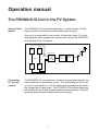

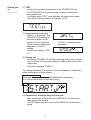
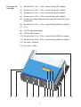
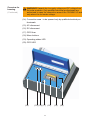
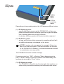

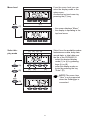

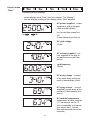

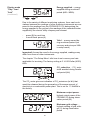
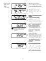
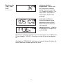

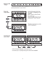
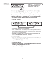
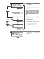
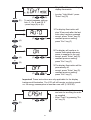

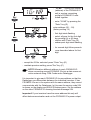
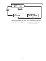

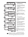
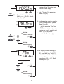


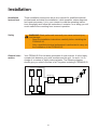

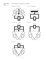

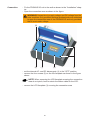
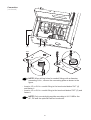


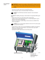

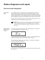
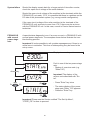
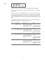


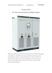

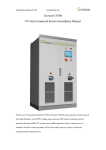


![Fronius Primo:, , [42,0426,0204,PB]](http://vs1.manualzilla.com/store/data/006066638_1-53eaca308649d96bdc628a0452b266c5-150x150.png)