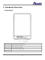
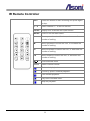
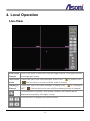
1
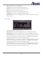
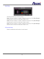
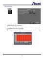
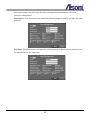
4 Channels Linux-Based Standalone Network Video Recorder NVR604LX User’s Manual Date: 5/21/2012 Firmware Version: V1.0.25 Content Content ....................................................................................................................................... 1 1. Introduction ......................................................................................................................... 3 Key Feature .............................................................................................................................. 3 2. Product Specifications ....................................................................................................... 3 3. Hardware Overview............................................................................................................. 6 Front Panel ............................................................................................................................... 6 Rear Panel ............................................................................................................................... 7 IR Remote Controller ................................................................................................................ 8 4. Local Operation................................................................................................................... 9 Live-View .................................................................................................................................. 9 Configuration .......................................................................................................................... 11 Camera Setup ..................................................................................................................... 11 Record Setup ...................................................................................................................... 16 Alarm Setup ........................................................................................................................ 17 Network Setup .................................................................................................................... 19 Authority Setup ................................................................................................................... 25 Disk Management ............................................................................................................... 27 System Setup ..................................................................................................................... 29 NVR Playback ........................................................................................................................ 33 Time Search ....................................................................................................................... 33 Event Search ...................................................................................................................... 34 Playback ............................................................................................................................. 35 Backup ................................................................................................................................ 36 System Log ......................................................................................................................... 37 5. Remote Access ................................................................................................................. 38 Search and Setup IP Address for NVR ................................................................................... 38 Live-View ................................................................................................................................ 40 Configuration .......................................................................................................................... 45 1 System ................................................................................................................................ 45 User Management .............................................................................................................. 46 System Upgrade ................................................................................................................. 47 Network Setting .................................................................................................................. 48 PPPoE Setting .................................................................................................................... 49 DDNS Setting ..................................................................................................................... 50 Mail / FTP Setting ............................................................................................................... 52 DHCP Server ...................................................................................................................... 54 NVR Setting ........................................................................................................................ 55 6. Backup and Playback ....................................................................................................... 56 Play the Recorded File in NVR’s HDD.................................................................................... 56 Play the Backup File ............................................................................................................... 58 Support List of Hard Disk Drive .............................................................................................. 60 2 1. Introduction Key Feature H.264 decompression format support. Real-time Display and Playback. Support 1080P (1920x1080) Camera for each channel. Audio Streaming/ Audio recording. Graphic User Interface. Support time-point backup function under network remote control mode. User can select any time period to process backup from remote side. Support time-search and event-search function under network remote control mode. Up to four online clients for independent remote control; individual live-time, play-back and time-search function available. Support Static/ DHCP IP and PPPoE, DDNS. Powerful mobile surveillance function, support JAVA, Blackberry, iPhone and Windows mobile. Support log function. 2. Product Specifications Video Mode Multiplex Record & Display Channel Max. 4 CH Support IP Camera H.264, MJPEG Compression Mode Support IP Camera Resolution Up to 1920 x 1080 Record & Display Frame Rate Up to 30FPS @ NTSC per channel Split Screen 1, 4 Video Output VGA output (D-Sub connector) Audio Audio Input 1 Microphone in (3.5mm phone jack) Audio Output 1 Earphone out (3.5mm phone jack) Audio Streaming Real-time audio 3 Audio Recording Yes Recording Recording Format H.264 Recording Video Resolution Depends on the streaming from IP camera, up to 1920x1080 Recording Frame Rate Depends on the streaming from IP camera, up to 30FPS @ NTSC per channel Recording Mode Manual / Schedule / Event Playback and Search Playback Speed Fast Forward: X2, X4, X8, X16, X32, X64 Fast Rewind: X8 Frame by Frame Playback Pause Time Search Yes Event Search Yes OSD and Control Interface On Screen Display and Setup Graphic User Interface on locally display Mouse Control Yes IR Remote Controller Yes Web Interface Remote access via IE browser, up to 4 clients simultaneously Storage and Backup Device Internal HDD SATA HDD x 2, for recording External USB Device USB Stick/HDD/ Burner, for backup Network Ethernet 100/1000 Base-T Network Protocol HTTP, TCP/IP, RTP/RTSP, 3GPP, SMTP, FTP, PPPoE, DHCP (Server & Client), DDNS, NTP, UPnP E-Mail Yes FTP Yes Alarm System Motion Detection Yes Video Loss Detection Yes Alarm Recording Yes Pre-alarm Recording Yes Buzzer Warning Yes Other Functions PTZ Control Yes Digital Zoom Yes 4 Privacy Mask Yes Password Protection Yes Firmware Upgrade Upgraded from USB, or from remote IE browser Web browsing requirement OS Windows 2000, XP, Vista, Windows 7 Web Browser Microsoft IE V7.0 (32-bit) or above Suggested Hardware Intel Core 2 Duo 1.66GHz, RAM: 1GB Graphic card: 128MB onboard RAM * Specifications are subject to change without notice 5 3. Hardware Overview Front Panel USB Ports: To connect mouse or USB device. HDD LED: Status indicator of Hard disk. REC LED: Status indicator of recording. Power LED: Status indicator of power on/off. IR Sensor: To receive the control signal from IR remote controller. 6 Rear Panel Open/ Lock: The clip to open or lock the top cap. Fan: Cooling fan. VGA Output: Connect to LCD monitor for locally display (D-Sub connector). Wire Saddle: Wire saddle. Power Connector: To connect the included power adapter. Audio Output: The 3.5mm phone jack allows connect to earphone or an amplified speaker, you can hear the voice of the NVR. Audio Input: The 3.5mm phone jack allows connect to a passive-type of microphone, the voice will be transferred to the IP camera. Network Connector: RJ-45 connector, Gigabit Ethernet port. 7 IR Remote Controller REC Press this button to start recording and press again to stop. 1~4 Select channel 1 ~ 4 with full screen. QUAD Display all 4 channels with quad screen. MENU Enter or exit the Main Menu. ▲ Move upward to select the icon, or increase the number of setting. ► Move rightward to select the icon, or increase the number of setting. ▼ Move downward to select the icon, or decrease the number of setting. ◄ Move leftward to select the icon, or decrease the number of setting. Enter selected items. COPY Switch channel format. Fast rewind playback. Picture by picture forward playback. Fast forward playback. Play back recorded video. Stop the playback. 8 4. Local Operation Live-View View Single Channel Click on the video of channel to view the single channel. Click again will back to multiple-split screen. Turn On/Off Audio There is an icon on the video indicates “Audio is ON” , or “Audio is OFF” . Click on this icon to turn on/off the audio of channel. Chatting to Channel There is an icon on the video indicates “Chatting is ON” , or “Chatting is OFF” . Click on this icon to turn on/off the chatting function of channel. Click this button to perform “Auto Switch” function, the channel will be displayed sequentially. Click again to stop. Click the button to display the related channel. 9 Click this button to display channels with 4-split screen. Click the button to pop-up the PTZ control panel. Click this button again to disable this function. Note: This function is only available for the PTZ camera or video server. Click this button to display the information of hard disk drive. In single channel mode, click this button and then use mouse to draw a range to zoom-in or zoom-out the video. Click this button again to disable this function. Click this button to display in full screen mode. Click on screen again will back to normal mode. Click this button to turn on or off the audio broadcast. You can talk to all channels when this function is ON. The icon on the video indicates “Audio broadcast is ON” - , or “Audio broadcast is OFF” - Click this button to enter the Playback Setup menu. Click this button to stop the manual recording. Click this button to start the manual recording. Click this button to enter the Setup menu. 10 . Configuration In Live-view mode, click button to enter the Setup menu. Camera Setup CAMERA 11 IPCam Setup 1~4: Click and select the channel to setup. Enable: Click the checkbox to decide performing the connection or not. IP Address: Use the virtual keypad to input the IP address of the IP camera or video server. Port: Use the virtual keypad to input the HTTP port number of the IP camera or video server. User: Use the virtual keypad to input the administrator’s login user name of the IP camera or video server. Password: Use the virtual keypad to input the administrator’s login password of the IP camera or video server. State: After click [Connect IPCAM] button, the connection status of the IP camera or video server will reveal among this column. [Connect IPCAM] button: After input the above information, click this button to connect to the IP camera or video server. [IPCam Quick Search]: Click this button to perform the “Search IP camera” function. 12 Click [Search Device] button, NVR will search the IP camera or video server which IP address is setup as the same domain as NVR’s IP address. Moreover, click the found device from the list can import the device information to the channel automatically without any manual key-in step. IPCam Video Setup 1~4: Click and select the channel to setup. Resolution: Click pull-down list to change the resolution of connecting device. Quality: Click pull-down list to change the image quality of connecting device. Frame Rate: Click pull-down list to change the frame rate of connecting device. IPCam Image Setup 1~4: Click and select the channel to setup. Display: Enable or disable the camera display on the screen or not. 13 Title: Setup the title of connecting device. Contrast: Click ◄ or ► to change the Contrast level. Brightness: Click ◄ or ► to change the Brightness level. Hue: Click ◄ or ► to change the Hue level. Saturation: Click ◄ or ► to change the Saturation level. Sharpness: Click ◄ or ► to change the Sharpness level. Switch Dwell: Click ◄ or ► to change the time (in second) while performing “Auto Switch” function. Motion Setup 1~4: Click and select the channel to setup. Relay Dwell: Click ◄ or ► to change the relay time or disable relay function. Buzzer Dwell: Click ◄ or ► to change the buzzer time or disable buzzer function. Area1 Sensitivity: Click the checkbox to enable or disable the detection of this area. Click ◄ or ► to change the sensitivity of detection. Click [Motion Area Setup] to draw the area for detect, the motion area is drawn in blue. Area2 Sensitivity: Click the checkbox to enable or disable the detection of this area. Click ◄ or ► to change the sensitivity of detection. Click [Motion Area Setup] to draw the area for detect, the motion area is drawn in green. Area3 Sensitivity: Click the checkbox to enable or disable the detection of this area. Click ◄ or ► to change the sensitivity of detection. Click [Motion Area Setup] to draw the area for detect, the motion area is drawn in red. 14 Mask Setup 1~4: Click and select the channel to setup. Area1: Click the checkbox to enable or disable the mask area. Click [Area Setup] to draw the area for mask, the mask area is drawn in blue. Area2: Click the checkbox to enable or disable the mask area. Click [Area Setup] to draw the area for mask, the mask area is drawn in green. Area3: Click the checkbox to enable or disable the mask area. Click [Area Setup] to draw the area for mask, the mask area is drawn in red. IPCam Audio Setup Enable or disable the audio function of each channel. 15 Record Setup RECORD Pre-Alarm Record Time: Click ◄ or ► to change the recording time of pre-alarm. The available value is from 0~30 seconds. Post-Alarm Record Time: Click ◄ or ► to change the recording time of post-alarm. The available value is from 5~99 seconds. Record Mode: Click pull-down list to change the recording mode. There are 3 modes: Manual, Schedule and Alarm trigger. 16 Alarm Setup ALARM Alarm Trigger Setup Alarm Auto Switch: Click the pull-down list to change the display mode when an alarm is triggered. When the alarm is triggered, the screen will switch to full screen, split screen or disable. Video Loss Detection: Click the pull-down list to enable or disable the “Video Loss” as an alarm. When the video loss is detected, the alarm will trigger. 17 Alarm Output Setup Video Loss Buzzer Time: Click ◄ or ► to change the buzzer time when video loss is detected. The available value is from 5~99 seconds. Video Loss Relay Time: Click ◄ or ► to change the relay time when video loss is detected. The available value is from 5~99 seconds. Alarm Event Setup There are six sort of events can be selected. When the selected items are happened and triggered, the alarm will be activated. 18 Network Setup NETWORK IP Address Setup IP Mode: Click the pull-down list to change the IP mode to Static IP or DHCP. IP Address: Use the virtual keypad to input the IP address of NVR. NetMask: Use the virtual keypad to input the subnet mask of the network. Gateway: Use the virtual keypad to input the IP address of default gateway. DNS1/ DNS2: Use the virtual keypad to input the IP address of DNS (Domain Name Server). WebPage Port: Use the virtual keypad to input the HTTP port of NVR. 19 PPPoE Setup PPPoE Setting: Click the pull-down list to enable or disable the PPPoE connection. User Name: Use the virtual keypad to input the user name (ADSL account) which provided from local ISP. Password: Use the virtual keypad to input the ADSL password which provided from local ISP. Password Confirm: Use the virtual keypad to input the password again to confirm. State: Present the current status of PPPoE connection. Send Mail After Dialed: Click the pull-down list to enable or disable this function. This device will send a mail with the Subject to a specific mail account when dialed successfully. Subject: Use the virtual keypad to input the subject of the Email will be sent. DDNS Setup DDNS Enable: Click the checkbox to enable or disable the DDNS function. 20 DDNS Server: Click the pull-down list to select DDNS provider. Host Name: Use the virtual keypad to input the registered host name (domain name) from the DDNS provider. User Name: Use the virtual keypad to input the login user name from the DDNS provider. Password: Use the virtual keypad to input the login password from the DDNS provider. Update Interval: Use the virtual keypad to input a period of time to update IP address. State: This field will display the message to indicate the status of DDNS service. The message will be: Updating: Information update. Idle: Stop service. DDNS registered successfully, now log by http://<hostname (username)>.<provider>.com: DDNS registration successful, can now link to the NVR with this URL address. Update Failed, the name is already registered: The hostname or username has already been used. Please change it. Update Failed, the name is already registered. Update Failed, please check your internet connection. Mail Setup Enable: Click the checkbox to select which event should send mail when it is triggered. Mail Server: Use the virtual keypad to input the IP address or URL of the send-mail server. 21 SMTP Port: Use the virtual keypad to input the port of the mail service. Default is 25. User Name: Use the virtual keypad to input the user name of the sender to login mail server and send the mail. Password: Use the virtual keypad to input the password of the sender to login mail server and send the mail. Sender’s Mail: Use the virtual keypad to input the sender’s mail address. Receiver’s Mail: Use the virtual keypad to input the receiver’s mail address. BCC Mail: Use the virtual keypad to input the mail address to receive the mail also. Subject: Use the virtual keypad to input the subject of the Email will be sent. FTP Setup Enable: Click the checkbox to select which event should send message to FTP server when it is triggered. FTP Server: Use the virtual keypad to input the IP address or URL of the FTP server. User Name: Use the virtual keypad to input the user name to login FTP server. Password: Use the virtual keypad to input the password to login FTP server. FTP Port: Use the virtual keypad to input the port of the FTP service. Default is 21. Path: Use the virtual keypad to input the file path on FTP server to save the sent file. 22 DHCP Server Setup Enable: Click the checkbox to enable or disable DHCP Server function. When the function is activated, the NVR can be treated as the DHCP server. The NVR will assign or distribute one of the IP address which is according to the setup IP address range (start and end IP Address.) to the connecting IP camera or video server (these devices must enable DHCP function as well). Start IP Address: Use the virtual keypad to input the start IP Address of DHCP server. End IP Address: Use the virtual keypad to input the end IP Address of DHCP server. Lease Time: Click ◄ or ► to change the lease time of DHCP server. UPNP Port Forwarding Setup Enable: Click the checkbox to enable or disable the “UPnP Port Forwarding” function. This function provides an easy way to configure the NAT (Network Address Translation) in router. If the router equips “UPnP Port Forwarding” function too, the NVR will ask the router to open the “External HTTP Port” and “External RTSP Port” for the NVR automatically. Therefore, you don’t need to configure the Port Forwarding 23 manually. Note: Not all routers equip “UPnP Port Forwarding” function. External HTTP Port: Use the virtual keypad to input the External HTTP Port. External RTSP Port: Use the virtual keypad to input the External RTSP Port. 24 Authority Setup AUTHORITY HDD Format: Click the checkbox to enable or disable the authority of HDD Format function. If enable this function, the user has to input password while performing HDD format. Anonymous User Login: Click the checkbox to enable or disable the authority of anonymous user login. If enable this function, the user does not have to input the username/ password and can view the Live-view via IE browser. Password Protection: Click the checkbox to enable or disable the authority of password protection. Keyboard Lock: Click the checkbox to enable or disable the operation of control bar which is on the right side of Live-view screen. The control bar cannot work when keyboard lock is activated. User Management 25 Among this page, user can setup the user management permission and the user authority management. Permission: Click this button will open the following page to modify and alter the user authority. Add User: Click this button will open the following page to distribute the authority and the permission for the new user. 26 Disk Management DISK Overwrite Mode: Click the pull-down list to enable or disable overwrite function. Hard Disk Full Warning: Click the pull-down list to change value with non-overwrite mode. When the ratio of remain space is below the value, it will enable audible alarm (If Audible alarm of Buzzer of Alarm Setup is ON). Auto Deletion: Click the pull-down list to enable or disable auto deletion function. Reserve Day: Click ◄ or ► to setup the reserve day. While enable auto deletion function, the data will be removed when reserve day is exceed the setting. The value can be setup between 1~30 days. Storage Information Click this button will open the following page to present the information of storage device. 27 Format HDD Click this button will open the following page, input the user name and password and then format the HDD. 28 System Setup SYSTEM NVR Name: Use the virtual keypad to input and assign the name to NVR. NVR ID: Click ◄ or ► to assign the ID for NVR. Language: Click the pull-down list to change the NVR language. Date Format: Click the pull-down list to change the date format. There are DD/MM/YYYY, YYYY/MM/DD and MM/DD/YYYY three modes. Version: The firmware version of the NVR. Software Update Click this button will open the following page, user can perform firmware update. 29 Configure Setup Click this button will open the following page. Click the checkbox to select which item can be setup by user. User can also load the setting to factory default, load the configure from USB and backup configure to USB. Time Setup Click this button will open the following page. [SYNC] button in “Time” block: Click this button can adjust and synchronize the time of NVR as the system time of PC. [SYNC] button in “NTP Setup” block: After enable the checkbox and then click this button, the time of NVR will synchronize to the NTP Server. Year/ Month/ Time: Click ◄ or ► to manually adjust the time of NVR. 30 Daylight Saving Time Setup Click this button will open the following page. After enable the daylight saving time function, the user can use the pull-down list to select the start time and the end time to perform daylight saving time. Status Display Setup Click this button will open the following page. Click the checkbox to enable or disable the item. The selected item will be displayed on Live-view screen. 31 Monitor Adjust Click this button will open the following page. Click ◄ or ► to adjust the monitor related setting, and select the monitor resolution of the VGA output. 32 NVR Playback In Live-view mode, click button to enter the Playback Setup menu. Time Search Time Search Select the date from the calendar and then observe the table on bottom. If this day contains the recorded data, the boxes in table will become to red. Click on the box to start the playback. 33 Event Search Event Search Click the event log item shown on the list to start the playback. Moreover, user can click [Event Filter] button to show the following page, select the specific event option to filter the event that shown on the list. 34 Playback Click on Video Click on the video of channel to view the single channel. Click again will back to multiple-split screen. Turn On/Off Audio There is an icon on the video indicates “Audio is ON” , or “Audio is OFF” . Click on this icon to turn on/off the audio of channel. Click this button to backup the playing recorded video (.264 video backup) and click this button again to finish the backup. For performing the single image backup (.Y42 single image backup), click to pause the playback and then click this button to backup the necessary image. Click this button to display channels with 4-split screen. Click the button to display the related channel. 35 Click this button and then use mouse to draw a range to zoom-in or zoom-out the video. Click this button again to disable this function. Click this button to display in full screen mode. Click on screen again will back to normal mode. Click the button to control the playback. Backup The Playback Setup menu also provides the backup function. Backup Device: Click the pull-down list to select the connected USB storage. Start Time/ End Time: Click ◄ or ► to change the start and end time for backup. Select Channel: Click the checkbox to select the channel for backup. After setup the above settings, click [Backup Now] button to start the backup. 36 System Log System Log System log reserves all of the system record. The maximum log quantity is 2000. To perform the further log filter action, click [Log Filter] button to show the following page. Select the specific event option to filter the log that shown on the list. 37 5. Remote Access The NVR has built-in web server, user can link to the NVR via IE browser, and the Live-view, playback, backup and configure the NVR remotely. Please follow the next pages to configure and do the remote access. Search and Setup IP Address for NVR IP Search is a utility that provides an easier, more efficient way to configure the IP address and network settings of the NVR and network camera in Local Network (LAN). It even provides a convenient way to set the network settings for multiple devices simultaneously. The software can be installed from the attached software CD. 1. Once IP Search has been successfully installed on the computer, double click the “IP Search” icon on the desktop. 2. IP Search searches all the network devices which connect to the intranet and lists on the window. Click [Search] button to search again. 3. From the list, select the device with the MAC Address that corresponds to the device that is to be configured. 4. Click and select one of the network devices, the network configuration of this device will show on the bottom, filling in the IP Address, Subnet Mask, Gateway and the others. 5. Click [Set] button to complete the configuration settings and save into the device. 6. Wait for 1 minute to let the device update the settings, and then click [Search] button 38 again to re-search the network devices. 7. Click and select the network device listed on the window and click [Open Web] button. It will open an IE browser and connect to this device directly. 39 Live-View Start the IE browser, type the IP address of the NVR in the address field: http://<IP of NVR> If the “HTTP Port” has been changed from “80”, type the URL as: http://<IP of NVR>:<HTTP Port> After link to the camera, it will show a dialogue box. Key-in the user name and password to log-in and open the web page of camera. The default user name and password are “admin” and “admin”. For the first time to view the camera video via IE, it will ask you to install the ActiveX component. If the installation failed, please check the security setting for the IE browser. 1. In IE, click on [Tools] [Internet Options…] 2. Click on [Security] Tab [Custom Level…] 3. In Security Settings, under [Download unsigned ActiveX controls], select “Enable” or “Prompt”. 4. In Security Settings, under [Initialize and script ActiveX controls not marked as safe], select “Enable” or “Prompt”. 5. When pop-up window with warning message, click [Yes] to save the settings. 40 1 2 3 4 5 When popup the following dialogue box, click [Yes]. 41 The web page of the NVR shows as following. If you are using IE 8.0 or above, please click “Compatibility View” icon to make this web page works properly: ② ① ⑦ ④ ③ ⑥ ⑤ Configuration : Go into the configuration page to set the parameters if necessary. Online Visitor : Shows how many users connect to this NVR. The maximum connecting user is 4. Status Bar : Shows system date/time and the status. Advanced Options : Right-click on the video, a window will be pop-up and list some advanced options, the options are: 42 Snapshot CHx : Click this option to take the snapshot and save it into the local PC. It will ask you where to save the file. Performance : Click this option and then select the speed to display the video. Use Overlay : After enable this option, the video will be displayed by using the hardware accelerator of display card. This will reduce the CPU loading and enhance the performance. Note: some display cards have incompatible issue with Overlay function. If the video is abnormal, please disable this option. Play Audio : Click this option to play the audio of this channel. Click again to turn off it. Playback Control : Click these buttons will perform the Playback functions. Function Buttons : Click these buttons will perform the following functions. Time-Point Backup : Click this button to download and backup the recorded video from NVR. Select the start and end time and then click [Save] button. It will ask you where to save the file. Note: the backup video can only be played by “A6Viewer.exe”, you can download this software in “Configuration” Page. Record : Click this button to manually record the video into the local PC. It will ask you where to save the video. Click on [Stop] button will stop the recording. Note: the recorded video can only be played by “A6Viewer.exe”, you can download this software in “Configuration” Page. 43 Full Screen : Click this button to view the video in full screen mode. Click this button again, or press the Esc key on keyboard, it will back to normal mode. 4-Split : Display 4 channels simultaneously. Single Channel : Display single channel one by one. You can also double-click the channel to enlarge it. PTZ Control : Click these buttons will perform the following functions. Pan / Tilt the camera: Click the direction buttons. Move camera back to the home position: Click Speed Adjust the speed of the camera movement: Select the speed from the pull-down list, higher value is faster. Zoom Adjust the zoom ratio: Pan/Tilt Control Click button. or button to zoom-in or zoom-out the camera. Auto Pan Preset Point Click Perform the Auto Pan function: to start “Auto Pan”, or click to stop “Auto Pan”. Select the preset point from the pull-down list, move the camera to the position as your wish, Set / Change Preset Point: and then click [Save] button to set the preset. Select the preset from pull-down list and then Go to Preset Point: click [Go], camera will go to the position. 44 Configuration System System Information Server Information Server Name: You can type a name into this field to identify this device. MAC Address: The MAC address of the Ethernet network card in the device. NTP Time Setting Time Zone: The time zone setting that has been setup in NVR. This setting cannot be configured remotely. NTP Server: The IP address or URL of the NTP server. After set up, click [Apply] to save the settings. 45 User Management You can add, remove and manage the users in this page. User Management HDD Format Password Check Enable or disable whether check the password to do the HDD format process. Anonymous User Login To allow user visit this device without login. Select to enable or disable this function. After set up, click [Apply] to save the settings. Add User To add a new user, click [Add User] button to open the pop-up window. Input the username, password and select the permission, and then click [OK] to add the user. User List This table lists the current users. Edit: To change the username and password, click [Edit] and modify the user in the pop-up window. Remove: To remove the user, click [Remove]. 46 System Upgrade This page allows user to upgrade firmware and restore the factory default settings. System Upgrade Firmware Upgrade The firmware can be upgraded online. To update the firmware, click [Browse…] to select the new firmware file, and then click [Upgrade] to the procedure. Load Default To load the factory defaults, click [Load] and then click [Yes] on the prompted window. To load the settings from previous backup settings, click [Browse…] to select the setting file, click [Load] and then click [Yes] on the prompted window. Backup Settings To backup the settings from NVR, click [Download] and select the location to store the file. 47 Network Setting Network Setting IP Assignment DHCP: If this device behinds a router and the router provides DHCP service, using DHCP, this device will get all network parameters from the router automatically. Static: Assign IP address, subnet mask, gateway, and DNS manually. HTTP Port: Set the port for HTTP connection. The default is “80”, change the port if you want to use router’s NAT (Network Address Translation) to make this device can be linked from Internet. UPnP Port Forwarding The “UPnP Port Forwarding” function provides an easy way to configure the NAT (Network Address Translation) in router. If the router equips “UPnP Port Forwarding” function too, this device will ask the router to open the “External HTTP Port” and “External RTSP Port” for this device automatically. Therefore, you don’t need to configure the Port Forwarding manually. Note: Not all routers equip “UPnP Port Forwarding” function. The device will report whether this function is successful after click [Apply] button. After set up, click [Apply] to save the settings. 48 PPPoE Setting If this device connects to an ADSL modem directly and want to use PPPoE connection, set the parameters in this page. PPPoE Setting PPPoE Connection Select [Enable] to use PPPoE. Type in user name and password for the ADSL connection. Send E-mail After Dialed If select [Enable], when connect to the Internet via PPPoE, this device will send a mail with the Subject to a specific mail account, this mail contains the public IP address of the ADSL connection. E-mail Subject The subject of the E-mail will be sent. After set up, click [Apply] to save the settings. 49 DDNS Setting This device supports DDNS, set the parameters in this page. DDNS Setting DDNS Setting There are several DDNS providers can be selected. Select the provider from the pull-down list, input Hostname, User name, Password and the Schedule Update time, and then click [Apply] to connect to the DDNS provider. Status This field will display the message to indicate the status of DDNS service. Updating: Information update. Idle: Stop service. DDNS registered successfully, now log by http://<hostname (username)>.<provider>.com: DDNS registration successful, can now link to the NVR with this URL address. Update Failed, the name is already registered: The hostname or username has 50 already been used. Please change it. Update Failed, the name is already registered. Update Failed, please check your internet connection. 51 Mail / FTP Setting To send out the event video to E-mail or FTP, please set up the configuration first. Mail / FTP Mail Setting Motion / Alarm: Select which event should be informed by Email. Send Mail Server: The IP address or URL of the send-mail server. Mail Port: The port of the mail service. Default is 25. User Name / Password: The user name and password of the sender to login mail server and send the mail. Sender’s Mail: The sender’s mail address. Receiver’s Mail: The receiver’s mail address. BCC Mail: The mail address to receive the mail also. 52 FTP Setting Motion / Alarm: Select which event should be informed to FTP. FTP Server: The IP address or URL of the FTP server. User Name / Password: The user name and password to log in the FTP server. FTP Port: The port of the FTP service. Default is 21. Store Path: The path to save the sent file. After set up, click [Apply] to save the settings. 53 DHCP Server Enable: Click the checkbox to enable or disable DHCP Server function. When the function is activated, the NVR can be treated as the DHCP server. The NVR will assign or distribute one of the IP address which is according to the setup IP address range (start and end IP Address.) to the connecting IP camera or video server (these devices must enable DHCP function as well). Start IP Address: Input the start IP Address of DHCP server. End IP Address: Input the end IP Address of DHCP server. Lease Time: Input the lease time of DHCP server. After set up, click [Save] to upload and save the settings into NVR. 54 NVR Setting In this page you can configure all settings in the NVR. After set up, click [Save] to upload and save the settings into NVR. 55 6. Backup and Playback The NVR provides a software is named “A6Viewer.exe”, this software is running under Windows, it can play the following files: The recorded file in NVR’s HDD. The recorded file that is backup by using USB device. The recorded file that is backup by using IE web browser. The snapshot file that is taken in web page of NVR by using IE web browser. You can find the “A6Viewer.exe” in attached CD, or download it from the web page of NVR in “Configuration” “Player”. Moreover, while perform the USB backup, this software will be included in the USB device automatically. Play the Recorded File in NVR’s HDD 1. Remove the HDD from NVR, and then connect the HDD to PC. 2. Run “A6Viewer.exe”, click [File] and then select [HDD Play]. 56 3. Click the pull-down list under “HDD Select” to select the HDD. 4. Select the date and time, and then click [Time Search] or [Event Search] to begin the searching. 5. Click on the desired video to play it. 6. You can convert the video to AVI file during playback, just click [Save AVI] button, and then select the folder and filename to save it. Click [Stop AVI] will stop the conversion. 57 Play the Backup File The “A6Viewer.exe” can also play the backup file in USB device and PC. 1. If you want to play the backup file in USB device, insert it to PC. 2. Run “A6Viewer.exe”, click [File] and then select [File Play]. 3. Click [Open] button under “File Select” to select the location contains the backup file. 4. Select the date and time, and then click [Time Search] or [Event Search] button. 58 5. Click on the desired video to play it. 6. You can convert the video to AVI file during playback, just click [Save AVI] button, and then select the folder and filename to save it. Click [Stop AVI] will stop the conversion. 59 Support List of Hard Disk Drive Brand Model Capacity Others SEAGATE ST380815AS 80 GB 7200 10 ST3160815AS 160 GB 7200 10 STM3250820AS 250 GB 7200 10 ST3250310SV 250 GB SV35.3 ST3400620AS 400 GB 7200 10 ST3500320SV 500 GB SV35.3 ST3500410SV 500 GB SV35.5 ST3500320AS 500 GB 7200 11 ST3500418AS 500 GB 7200 12 ST3500312CS 500 GB Pipeline HD .2 ST3750640AS 750 GB 7200 10 ST3750330AS 750 GB 7200 11 ST31000333AS 1 TB 7200 11 ST31000340AS 1 TB 7200 11 ST31000340NS 1 TB Barracuda ES.2 ST31000340SV 1 TB SV35.3 ST31000322CS 1 TB Pipeline HD .2 ST31000525SV 1 TB SV35.5 ST31000524AS 1 TB (SATA III) 7200 12 ST1500DL003 1.5 TB (SATA III) Barracuda LP ST31500341AS 1.5 TB 7200 11 ST32000542AS 2 TB Barracuda LP WD1600AAJS 160 GB 7200 CB WD2500AAKS 250 GB 7200 CB WD2500AVVS 250 GB 7200 GP WD3200AVVS-73L2B0 320 GB 7200 GP WD5000AACS 500 GB 7200 GP WD5000AVVS 500 GB 7200 GP WD5000AAKS 500 GB 7200 CB WD 60 HITACHI WD5002ABYS 500 GB 7200 RE WD5000AAKX 500 GB (SATA III) Caviar Blue WD6400AAKS 640 GB 7200 BLUE WD6400AVVS 640 GB 7200 GP WD7500AACS 750 GB 7200 GP WD7500AVVS 750 GB 7200 GP WD10EACS 1 TB 7200 GP WD10EADS 1 TB Caviar Green WD10EVDS 1 TB Green Power WD10EVVS 1 TB 7200 GP WD10EARS 1 TB Caviar Green WD10EALX 1 TB (SATA III) Caviar Blue WD15EADS 1.5 TB 7200 GP WD15EARS 1.5 TB 7200 GP WD15EURS 1.5 TB 7200 GP WD5000AVDS-63U7B0 1.5 TB 7200 GP WD15EVDS 1.5 TB 7200 GP WD20EADS 2 TB 7200 GP WD20EVDS-63T3B0 2 TB 7200 GP WD20EARS 2 TB Caviar Green WD20EURS 2 TB 7200 GP WD30EURS 3 TB CE-GP HDS721616PLA380 160 GB 7200 HDT725025VLA380 250 GB 7200 HDT725032VLA360 320 GB 7200 HDP725050GLA360 500 GB 7200 HCP725050GLA380 500GB 7200 HDT721010SLA360 1 TB 7200 HDS721010CLA332 1 TB 7200 HDS722020ALA330 2 TB 7200 61