1
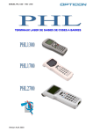
User’s Manual
Laser Terminal PHL 1700
Cradle IRU 1700
USER’S
MANUAL
PHL 1700
LASER TERMINAL
/ IRU 1700
CRADLE
CAUTION: This user’s manual may be revised or
withdrawn at any time without prior notice.
Copyright 2000, Opticon Sensors Europe B.V.
All rights reserved.
This manual may not, in whole or in part, be copied,
photocopied, reproduced, translated or converted to
any electronic or machine readable form without
prior written consent of Opticon Sensors Europe.
Limited warranty and disclaimers
By opening the package of this product you agree to
become bound by the liability and warranty conditions
as described below.
Under all circumstances this manual should be read
attentively, before installing and or using the product.
In no event, Opticon Sensors Europe will be liable
for any direct, indirect, consequential or incidental
damages arising out of use or inability to use both
the hardware and software, even if Opticon has been
informed about the possibility of such damages.
A serial number appears on all Opticon products.
This official registration number is strictly related to
the device purchased. Make sure that the serial
number appearing on your Opticon device has not
been removed. Servicing by our Repair Department
can only be carried out under warranty.
All Opticon products are warranted for a period of
one year after purchase, covering defects in material
and workmanship. Opticon will repair or, at its opinion,
replace products that prove to be defective in material
or workmanship under proper use during the warranty
period.
Opticon will not be liable in case modifications are
made by the customer. In such case the standard
repair charge will be applicable. The standard charge
for repair will also be applicable in case no defect is
found at all. These rules also apply for products that
are still under warranty. Therefore, you are advised
to have the product specifications always at hand.
Trademarks used are property of their respective
owners
PHL-ver6-sv / printed 03 03
CONTENTS
page
1
INTRODUCTION
3
2
INSTALLATION
4
2.1
UNPACKING
4
2.2
2.2.1
2.2.2
2.2.3
2.2.4
2.2.5
DETAILED VIEW
Dimensions of terminal
Details of terminal
Display of terminal
Dimensions of cradle
Details of cradle
5
5
5
6
7
7
2.3
2.4
2.4.1
2.4.2
HANDLING PRECAUTIONS
ASSEMBLY
Terminal
Cradle
8
9
9
9
2.5
INSTALLING,
REPLACING AND CHARGING
10
Required batteries
11
When to replace or recharge the
main battery?
11
When to replace the backup
battery?
11
How to remove the main battery? 11
How to install the main battery
12
How to recharge the rechargeable
battery pack in the cradle?
12
How to (re)place the backup battery
in the terminal?
13
BATTERIES
2.5.1
2.5.2
2.5.3
2.5.4
2.5.5
2.5.6
2.5.7
2.6
2.6.1
2.6.2
2.6.3
13
13
13
2.6.4
2.6.5
INSTALLING IN A SYSTEM
Power supply for cradle
DIP switch settings on cradle
Connect cradle to computer/
modem
Connect network of cradles
Terminal on cradle
3
OPERATION OF THE TERMINAL 15
4
SCANNING BAR CODES
16
4.1
4.2
4.3
SCAN POSITION
Reading the bar codes
If you have problems with the
read operation
16
16
13
13
13
16
USER’S
MANUAL
PHL 1700
LASER TERMINAL
/ IRU 1700
CRADLE
page
5
PIN OUT
17
5.1
5.2
5.3
17
17
5.4
RS232C cable for terminal PHL1700
Modem cable for terminal PHL1700
RS485 cable for network of cradle
IRU1700
RS232 cable for cradle IRU1700
17
17
6
SPECIFICATIONS
18
6.1
6.1.1
6.1.2
6.1.3
6.1.4
6.1.5
6.1.6
6.2
6.2.1
6.2.2
6.2.3
6.2.4
6.2.5
SPECIFICATIONS TERMINAL
Electrical specifications
Optical specifications
Physical specifications
Functionality
Environmental specifications
Supported symbologies
SPECIFICATION CRADLE
Cradle models
Electrical specifications
Functionality
Environmental specifications
Physical specifications
18
18
18
18
18
19
19
19
19
19
19
19
19
7
TROUBLESHOOTING
20
7.1
7.2
7.3
7.4
7.5
COMMUNICATION PROBLEMS
READ OPERATION PROBLEMS
BATTERY CHARGING PROBLEMS
TERMINAL PROBLEMS
CRADLE PROBLEMS
20
20
21
22
22
8
PRODUCT ORDERING
INFORMATION
23
The general use and functioning of the
terminal together with the cradle will be
described in this manual.
The exact behavior of the terminal
depends on the user application that is
running. For instructions about applications
please consult the documentation of
that software.
1
INTRODUCTION
This terminal is a compact, programmable
handheld terminal, and is well suited for a
variety of indoor portable applications. It has a
built-in laser scanner that can scan all popular
bar code labels at varying distances.
User’s applications can be downloaded to the
terminal to adapt the terminal to the user’s
situation.
Operating power is supplied by the main
battery. The main battery may consist of a
rechargeable Ni-MH battery pack (to be
charged in cradle), or dry cell batteries, either
non-rechargeable or rechargeable (to be
charged in an external charger).
The cradle can be equipped with a transceiver
function only, for terminals with dry cell batteries,
this will be sufficient. The cradle can also be
equipped with both transceiver and charger.
The charger is needed for terminals with a
rechargable battery pack.
The IrDA interface on the terminal enables
you to communicate with other devices that
use IrDA communication, like portable
computers, notebooks and organisers.
Additionally a RS232 cable can be used.
The RS232 cable can be used for direct
communication between the (host) computer
system and the terminal, for example to
download software to the terminal.
Please read this manual carefully
before using the terminal, to maximise
the efficiency of this terminal.
3
USER’S
MANUAL
PHL 1700
LASER TERMINAL
/ IRU 1700
CRADLE
Do not remove the label !
On the back of every unit you will find a label.
The label is attached by the manufacturer and
includes information about the function it
supports and a serial number.
Do not remove it.
PHL1600-10
2
part nr:
O2500000010
serial nr: 000001
battery: LR6x2 or Ni-MH,
CR2032x1
rating:
DC 3V,3V
2
supply 0.48W
IRU-1600 transceiver/charger
part nr: O2520000015
serial nr: 000001
SPECIMEN
input: DC 5V
4A
INSTALLATION
2.1 UNPACKING
When you remove the packing, please check
for any physical damage. We recommend that
you save all packing material, as it should be
used whenever you need to ship your terminal
(eg. for service). Damage due to improper
repacking is not covered by the warranty.
Apart from the terminal or cradle, additional
items might be ordered and supplied.
If there are any missing parts please contact
your supplier.
RS232 download cable for terminal
Modem cable for terminal
Protective bag for terminal
RS232 cable for cradle
RS485 cable for cradle
Modem cable for cradle
PHL1700: Terminal
IRU1700: Cradle
Terminal,
can be delivered as:
model with dry cell
batteries
model with rechargeable
battery pack
Cradle body:
can be delivered as:
model SV
model T
model T/C
Battery case,
depending on the model,
there are 2 options:
Battery case with
2x AA-size dry cell
penlite batteries
AC adaptor
depending on the model:
9V DC adaptor
for model SV and T
5V DC adaptor
for model TC
NiMH rechargeable
battery pack (1 x)
Wall mount panel + screws
Backup battery
Hand strap
4
Additional items
only supplied if ordered
Walll mount spacer +
screws + base plate
USER’S
2.2 DETAILED VIEW
2.2.1 Dimensions of terminal
MANUAL
PHL 1700
LASER TERMINAL
/ IRU 1700
CRADLE
1. Reading window
laser beam for barcode reading will be
emitted from here
2. Optical interface window
for infra red communication
3. LCD Display
for displaying information
4. LED indicator
can be used to indicate results, for example
bar code reading /status of communication
2.2.1 Details of terminal:
5. Trigger key definable by user’s application
typical use: read key, switches laser beam
on for barcode reading
6. Quick keys definable by user’s application
typical use: menu scroll keys or yes/no input
7. Power key right key, NOT definable
for switching power On/Off
Control keys definable by user’s application
for controlling basic functions
typical use as below
CLR : Cancel input
BS : Back space
S
: Shift key
“S”on the LCD display indicates
the terminal is in the shift mode
8. Character keys definable by user’s application
typical use: for input of alpha-numeric and
punctuation characters
9. ENT key definable by user’s application
typical use: for confirming input
10. Function keys definable by user’s application
user programmable keys, to be used
together with shift key.
typical use as shown on next page
11. Battery case cover
for housing main battery
12. RS-232C connector
for connecting external device, or for system
expansion, through Opticon RS232 cable
13. Hand strap pillar
for attaching hand strap.
14. Charging contacts
only for the model with rechargeable
battery pack.
5
USER’S
MANUAL
PHL 1700
LASER TERMINAL
/ IRU 1700
CRADLE
Description of the function keys
2.2.3 Display of terminal
In the shift mode, back light on/off, contrast
adjustment, and cursor movement can be
done by these keys.
The user’s application can give different
definitions to the keys
The liquid crystal display of the terminal is
typically used to show program prompts,
instructions and data, as defined in the user’s
application.
shift mode
functions:
F1 (-)
F2 (DEL)
F3 (SP)
F4 (BL)
F5 (<--), F6 (-->)
F7 ( ), F8 ( )
The display has the following default options:
input minus sign
delete one character
input space
toggle with back light
move cursor
adjust contrast
Special purpose symbols in display:
The symbols will be shown in the bottom part
of the display and indicate status.
Description of the display indicators
Main Battery indicator
Off: Sufficient battery power
On: Battery low.
Replace battery immediately.
Backup Battery indicator
Off: Sufficient battery power
On: Battery low.
Replace battery immediately.
Alpha mode on
(Shift-key activated)
Backlight
The display is provided with a backlight.
When the backlight is turned on, the power
consumption increases. To extend the life time
of your batteries use the backlight as little as
possible.
6
USER’S
2.2.4 Dimensions of the cradle
MANUAL
PHL 1700
LASER TERMINAL
/ IRU 1700
CRADLE
1. RS 232 C socket
for connecting to PC or modem, through
Opticon RS232 cable
2. RS 485 socket
for connecting another cradle in multi-drop
RS485 network, through Opticon RS485
cable
2.2.5 Details of cradle
3. LED indicator
indicating status of:
POWER
red : power on
green: terminal is on cradle
SD/RD
red : receive data
green: send data
BATT *
red : charging battery
green: charging is ready
*) BATT status is only for model TC and SV
4. Switch for terminal detection
to detect if a terminal is placed on the
cradle
5. DC input socket
input for AC adaptor
6. Power switch
7. DIP switches
setting parameters of the infra red interface
switches are located behind the cover
8. Data Transmission
Interface for optical data transmission
9. Contact for recharging
only for the model SV and TC
10. Battery spare slot for recharging
quick charge NiMH pack
only for the model transceiver/charger
11. Refresh switch
refresh-discharge NiMH pack
only for the model transceiver/charger
12. Wall mounting holes
7
USER’S
MANUAL
PHL 1700
LASER TERMINAL
/ IRU 1700
2.3 HANDLING PRECAUTIONS
CRADLE
Use of the terminal
Operate the terminal keys by
pressing them lightly with your
fingertips or with something soft
and round.
Pressing the keys with a sharp
pointed object (for eg. a ballpoint) can damage the keys.
To avoid malfunctioning and to ensure years
of trouble free operation, pay attention to the
following:
General use
Do not use or leave the product
in extremely hot areas - like
direct sunlight, near a heater,
or in a car - or in areas that are
very cold, humid, moistured or
dusty.
Avoid temperature changes.
Sudden temperature changes
can cause condensation to form
on the terminal. Using the terminal while condensation is present can cause malfunction.
Always wait until the condensation
clears naturally before attempting
operation.
Do not expose the product to
rain or water splash
!
Do not subject the the product
to very strong impact, do not
throw or drop the terminal from
large heights.
Do not leave the terminal in an
area where static charge is accumulated, or near devices where
electromagnetic emission is generated.
Do not allow a mechanical
shock to the product.
General cleaning instructions
!
Clean the exterior by wiping it
with a soft, dry cloth. Do not
use much water.
The charging contacts of
terminal and cradle must stay
as clean as possible to maintain optimal charging capacity.
Do not use thinner, white spirit
or other solvents. These can
discolour the case and the keys
and has a negative effect on
the lifetime of the keys.
Use of the cradle
Do not place any other product than the
PHL 1700 terminal in the IRU 1700 cradle.
Cleaning of the cradle
Avoid touching the contacts in the cradle.
Do not use water when cleaning the cradle.
This can cause malfunction in the chargers.
8
Do not place any objects on top
of the terminal. Do not lay the
terminal face down.
Doing so can cause accidental
operation of the [PW] key or
[ENTER] key, which can discharge
your batteries or change settings
you do not want to be changed.
Cleaning of the terminal
Clean the optical interface window periodically.
Maintenance
There are no user-serviceable
parts inside the terminal or the
cradle. So do not try to take it
apart.
The manufacturer will not be
liable for any damage caused
by the customer.
In case of malfunction that can not be solved
by the trouble-shooting instruction in the
appendix, please consult our service
department.
USER’S
2.4 ASSEMBLY
Follow the next steps to make your terminal
ready for installation in a system, that is
described further in the manual.
MANUAL
PHL 1700
LASER TERMINAL
/ IRU 1700
CRADLE
Wall mounting instructions
First mount the wall
mount panel on the
cradle.
2.4.1. Terminal
To avoid drop use the hand strap.
Fix the small cord of the
strap around the
pillar.
Insert the handle
in the thin loop.
!
Do not swing the
terminal around.
Start with a full battery
To be sure you start with a full battery,
charge the battery pack according to the
instructions in the next chapter.
Click the battery pack into the terminal,
as instructed in the next chapter.
Locate the place for
mounting and attach
the base plate by
tape.
Mark the position of
the holes of the base
plate. (ref. 1)
Remove the base
plate.
Screw in the screws
with spacers on the
marked positions.
(ref. 2)
Align the body with its
mounting holes to the
spacers. (ref. 3)
Slide down the body
and fix it on the wall.
2.4.2 Cradle
Place for mounting.
Place the cradle in normal office
conditions.
Avoid a place under strong light.
Otherwise IrDa communication may be
disturbed.
Wall mount panel
When the cradle is mounted on the wall, the
wall mount panel will keep the terminal on its
position. As a second function the panel will
protect the IrDa window from both terminal
and cradle from direct sunlight.
For power connection read the ‘installing in a
system’ part further in the manual.
9
USER’S
MANUAL
PHL 1700
LASER TERMINAL
/ IRU 1700
2.5 INSTALLING, REPLACING
AND CHARGING BATTERIES
Wrong use of batteries might cause
serious damage
to the terminal or to the cradle.
In order to avoid damage
it is very important to take notice
of the instructions.
!
!
Follow the instructions for installing,
changing and removing the batteries
very strictly.
The products are not warranted for
damage, defects, malfunction or loss of
data, resulting from incorrect use of
batteries.
Only use recommended batteries.
When other batteries are used, defects or
other problems can occur. Before installing
(new) batteries, please make sure you are
using the recommended batteries.
!
Do not make a mistake regarding the
polarity (+ , -) of the battery.
The terminal will not work when the
polarity is incorrect.
!
Never remove the main battery pack
while the terminal is turned on.
Doing so can cause data in the terminal
to be deleted.
!
!
10
Insert full batteries before use of the
terminal.
When you do not use the terminal for
a long time, make sure the main
battery has enough capacity.
When there is not enough capacity the
backup battery will be used up.
CRADLE
2.5.1 Required batteries
The terminal needs both main battery and
backup battery for operation.
Main Battery
The main battery can consist of:
Rechargeable Opticon battery pack (NiMH),
to be recharged when placing the terminal
PHL1700 in the cradle IRU1700.
Dry cel Opticon batteries (Alkaline).
To be used together with Opticon battery
case for dry cell batteries.
These batteries are not rechargeable.
Other batteries. All batteries have to be
used together with Opticon battery case
for dry cell batteries.
Batteries that are not supplied by Opticon
must be AA-size and absolutely leakproof.
If rechargeable batteries are used, they
need to be recharged by a separate
battery charging device.
Opticon recommends to use Opticon batteries
(Opticon rechargeable battery pack or Opticon
dry cell batteries) only.
Backup Battery
Use only one type of battery for backup:
Backup battery:
CR2032 Li (Lithium, button type).
USER’S
MANUAL
2.5.2 When to replace or recharge the
main battery?
There are 2 reasons for replacing (or charging)
the main battery;
as soon as possible after the battery
indicator
appears on the display.
when you are not using the terminal for an
extended period.
For instructions of (re)placing the main battery
see paragraph 2.5.4 and 2.5.5.
For instructions for charging the rechargeable
battery pack see paragraph 2.5.6.
2.5.3 When to replace the backup
battery?
When low battery mark
appears,
replace the battery without delay.
PHL 1700
LASER TERMINAL
/ IRU 1700
CRADLE
2.5.5 How to install the main battery
Before installing a battery case with penlite batteries:
Make sure you use
the right battery size.
Place 2 batteries in
the battery holder
aligning plus (+) and
minus (-) ends as
shown on the battery
holder.
The instructions for installing the battery pack
are also applicable for the battery holder with
penlite batteries.
Remove the battery
case cover. Press the
shaped part
with some force, and
pull it up.
For instructions of (re)placing the backup
battery see paragraph 2.5.7.
2.5.4 How to remove the main battery?
Remove the battery
case cover. Press the
shaped part
with some force, and
pull it up.
Remove the entire
battery case cover.
Make sure that the
direction of the
battery case is correct
and put the battery
case in.
Remove the entire
battery case cover.
Fit battery case cover.
To take the battery
case out, pull one side.
11
USER’S
MANUAL
PHL 1700
LASER TERMINAL
/ IRU 1700
2.5.6 How to recharge the rechargeable
battery pack in the cradle?
CRADLE
2.5.7 How to (re)place the backup battery
in the terminal?
!
Make sure that the main battery
is full enough while changing the
backup battery.
!
Only use CR2032 Li
(Lithium, button type) battery.
Charging battery pack inside terminal
Applicable for cradle model SV and TC:
Place the terminal in the cradle.
The battery will be charged during approx.
4 hours.
The application in the terminal determines the
indication of the charging procedure as (if
applicable) shown to the user.
Charging separate battery pack in cradle’s
spare slot
Applicable for cradle model TC:
Quick charge
Place the rechargeable battery pack in the
battery holder on the cradle.
After checking the battery status (indicated
by blinking green LED), the recharging
starts (indicated by by a solid blinking red
LED).
After approx. 1 hour the charging is
completed. (indicated by a solid blinking
green LED)
Refresh discharge
A rechargeable battery has an so called ‘memory
effect’, which deteriorates full charging when
recharging is executed before the battery
capacity becomes empty. When the memory
effect is recognised, activate the refresh
discharge. Use this feature sparingly, when too
often used, it may damage the battery.
Place the rechargeable battery pack in the
battery holder on the cradle.
Press the refresh switch and discharging
starts (indicated by an orange LED)
The discharge completes in approx. 4 hours,
and the quick charge follows immediately.
Remove the battery
case cover. Press the
shaped part
with some force, and
pull it up.
Remove the entire
battery case cover.
Open the lid of the
holder for the backup
battery.
If applicable:
Remove old battery,
using a pointed
object for easy
removal.
Make sure that the
positive side of the
(new) backup battery
is pointed upwards.
Place the backup
battery.
Close the holder
Close the battery
case cover.
12
USER’S
MANUAL
PHL 1700
LASER TERMINAL
/ IRU 1700
CRADLE
2.6 INSTALLING IN A SYSTEM
2.6.3 Connect cradle to computer/modem
!
Exercise caution at all times when
working with AC-powered equipment.
!
Turn off your devices before
installation.
!
Because of the special pin-out of the
connectors, use the cables supplied
by the manufacturer.
!
When you need another cable for a
certain device, that is not supplied,
contact your supplier to purchase the
right cable. In case another cable is
used, take notice of the pin-out
specifications further in this manual.
2.6.1 Power supply for cradle
!
Make sure that you use the right
power supply.
Use for model T and SV: 9V DC adaptor
Use for model TC: 5V DC adaptor
2.6.2 Dip switch settings on cradle
Setting the DIP switches on or off will result in
enabled or disabled functions of the cradle.
(see table on next page)
Make sure power is switched off.
Open the cover of the DIP switches on the
bottom of the cradle in order to reach the
DIP switches.
Connection sequence (see diagram and
dipswitch settings on next page)
Shutt off the computer.
Make sure cradle is disconnected.
Place the cradle in normal office conditions,
avoid a place under strong light (1).
Set proper baudrate on cradle (2), use
same baudrate as set on computer.
Connect the interface cable (3).
Connect the power supply (4) and power up
by power switch.
Power up the computer.
2.6.4 Connect network of cradles
(see diagram on next page)
Only 1 cradle in the network will be
connected to the PC through one RS232
cable. On this cradle the DIPswitch for
RS232 connection must be enabled.
Through this connection all cradles can
communicate to the PC.
A maximum of 16 cradles can be connected
in a network through RS485 cables. For the
cradles that are not directly connected to
the PC the DIPswitch for RS232 connection
must be set to off.
All cradles need to have the same baudrate,
for model SV to be set by dipswitch.
The first and the last cradle in the network
must have the termination resistors set by
DIPswitch.
2.6.5 Terminal on cradle
!
Do not place any other product than
the PHL1700 terminal in the IRU1700
cradle.
Place the terminal on the cradle as shown in
the illustration:
(Indicator on cradle: green LED)
13
USER’S
MANUAL
PHL 1700
LASER TERMINAL
/ IRU 1700
CRADLE
6
6
1
2
3
4
5
ON
1
2
3
4
5
ON
*) see DIP switch table on next page
**) see power voltage on previous page
14
USER’S
MANUAL
PHL 1700
LASER TERMINAL
/ IRU 1700
3
OPERATION OF
THE TERMINAL
CRADLE
Dip switch settings for cradle IRU-1700
model T and TC:
ON
DIP
SWITCH
FUNCTIONS
ON
OFF
1 2 3 4 5 6 7 8
SW 1
RS 232
ON for connection
in use
not
in use
SW 2
SPARE
--
--
SW 3
SPARE
--
--
SW 4
SPARE
--
--
SW 5
SPARE
--
--
SW 6
SPARE
--
--
SW 7
RS485
TERMINATOR
in use
not
in use
SW 8
RS485
TERMINATOR
in use
not
in use
DIP SWITCH
OFF ON
Dip switch settings for cradle IRU-1700
model SV:
1 2 3 4 5 6
DIP
SWITCH
FUNCTIONS
ON
OFF
SW 1
RS 232
ON for connection
in use
not
in use
SW 2
RS485
TERMINATOR
in use
not
in use
SW 3
RS485
TERMINATOR
in use
not
in use
SW 4
BAUDRATE *
--
--
SW 5
BAUDRATE *
--
--
SW 6
BAUDRATE *
--
--
OFF
DIP SWITCH
OFF ON
*)
BAUDRATE
SW
4
SW
5
SW
6
1200
OFF
OFF
OFF
2400
ON
OFF
OFF
4800
OFF
ON
OFF
9600
ON
ON
OFF
19200 (default)
OFF
OFF
ON
38400
ON
OFF
ON
115200
OFF
ON
ON
ON
ON
ON
AUTO (PC controlled)
The functionality of the terminal is determined
by software, the so-called user application,
that is running on the terminal.
Usually, the terminal is not equipped with
software and has no functionality. At first the
user application must be loaded before the
terminal can be used for barcode scanning.
Tools for developing a user application on the
PC for use on the terminal, as supplied by
Opticon are:
Application Generator
PotStar (Limited or Professional)
C language: Microtec ANSI-C compiler
and C library for handheld terminals.
The user application must be downloaded
from the PC into the terminal. You can use the
cradle, an RS232 cable or an infrared adapter
for communication between the terminal and
the PC. A program on the PC will send the
user application to the terminal, where it is
stored in FlashROM memory.
When the functionality of the terminal is defined
by the application it is ready for operation.
In a typical application you will press the trigger
key and scan a bar code label as described in
the next chapter. Scanned data and data
entered from the keyboard is stored in the
terminal's RAM. The user application can use
this data in subsequent steps.
The collected data can be transmitted to the PC
for further processing. For data transmission
you can use the cradle, an RS232 cable or an
infrared adapter to connect the terminal to the
PC.
15
USER’S
MANUAL
PHL 1700
LASER TERMINAL
/ IRU 1700
CRADLE
The terminal is a Class I laser product conforming
to the strictest laser safety standards.
However, we recommend that you avoid looking
directly into the laser beam emitter, or pointing
the laser beam directly into someone’s eyes.
4
SCANNING
BAR CODES
!
Please take care of the handling
precautions.
!
Please make sure that the terminal is
installed according to the installation
instructions.
!
Never remove the main battery pack
while the terminal is turned on.
Doing so can cause data in the terminal
to be deleted or corrupted.
Fit the bar code in the laser beam from
margin to margin and pass the scanner
downward over the bar code, as shown in the
scan position illustration.
X
X
X
X
incorrect read
scan positions
4.1 Scan Position
When reading a small bar code, decrease the
distance between the terminal and the bar
code. For larger bar codes, position the terminal
so that the bar code fits into the laser beam.
When reading a very high density bar code,
decrease the distance between the terminal
and the bar code. For a low density bar code,
increase the distance between the terminal
and bar code.
4.2 Reading the bar codes
The scanning sequence is defined by the
user’s application. A typical sequence is:
Press the [PW] key to turn power on.
Check the display for the message:
READ BAR CODE
Point the terminal to the bar code and
press the Trigger key.
Point the laserbeam to the barcode as
shown in the scan position illustration.
The barcode will be read and the reading
results will be indicated.
16
good read
scan position
X
X
A ‘Good Read’ means that the scanner has
effectively recognised and decoded the bar
code. In most cases, the application program
will provide an indicator signal or a buzzer
signal to indicate a good read to the user.
When the read is incorrect you can try again,
paying attention to the instructions stated
below.
4.3 If you have problems with the read
operation
Change the angle between the bar code
and the terminal.
Change the distance between the bar
code and the terminal.
If the bar code is larger than the laser
beam, try moving the terminal a bit further
away from the bar code.
USER’S
5
MANUAL
PHL 1700
LASER TERMINAL
/ IRU 1700
CRADLE
PIN-OUT
5.1 RS232C cable for terminal PHL1700
5.2 Modem cable for terminal PHL1700
5.3 RS485 cable for network of cradle
IRU1700
5.4 RS232 cable for cradle IRU1700
5.1
5.2
1
25
9
1
RS232
cable
DB 9
female
Modular
plug
(10 pins)
Signal
DB 9
connector
Female
Signal
1
2
3
4
5
6
7
8
9
10
DC IN
DC IN
TxD
RxD
RTS
CTS
DTR
DSR
GND
GND
2
3
8
7
6
4
5
-
RxD
TxD
CTS
RTS
DSR
DTR
GND
-
5.3
Network
cable
RS485
1
1
1
1
6
6
Modem
cable
DB 25
male
Modular
plug
(10 pins)
Signal
DB 25
connector
Male
Signal
1
2
3
4
5
6
7
8
9
10
DC IN
DC IN
TxD
RxD
RTS
CTS
DTR
DSR
GND
GND
2
3
4
5
20
6
7
-
RxD
TxD
CTS
RTS
DSR
DTR
GND
-
5.4
1
1
9
9
Modular
plug
(6P6)
Modular
plug
(6P6)
Signal
1
2
3
4
5
6
2
3
4
5
-
RD+
RDSD+
SD-
RS232
cable
DB 9
DB 9
male
Signal female
(cradle)
(PC)
3
2
6+1
5
4
8
7
TxD
RxD
DSR
GND
DTR
CTS
RTS
2
3
4
5
6+1
7
8
Signal In/Out Note
(cradle)
RxD
TxD
DTR
GND
DSR
RTS
CTS
OUT
IN
OUT
OUT
not used
ON (fixed)
not used
ON (fixed)
17
USER’S
MANUAL
PHL 1700
LASER TERMINAL
/ IRU 1700
CRADLE
6.1.2 Optical specifications
Light source
6
650 nm visible laser diode
Scan rate
100 scans/sec
Decode rate
100 decodes/sec
Reading width
60 mm at 30 mm
98 mm at 100 mm
Resolution at PCS 0,9 0.15 mm (6mil)
Depth of field
SPECIFICATIONS
0 - 140 mm (at PCS 0.9, res. 0.25)
6.1.3 Physical specifications
Dimensions (l x w x d) 172 x 62 x 44 mm
6.1 SPECIFICATIONS TERMINAL
6.1.1 Electrical specifications
Main battery
Main battery
operating time
rechargeable pack: Ni-MH
dry cell: Alkaline penlite
optional: other 2 x AA-size
penlite
Ni-MH: When making every 5
seonds 1 scan with 1 sec
laserbeam on and 0.2 sec.
green LED on and 0.2 sec.
buzzer on, operating time is:
approx. 34 hours
Alkaline: When making every 5
seonds 1 scan with 1 sec
laserbeam on and 0.2 sec.
green LED on and 0.2 sec.
buzzer on, operating time is:
approx. 67 hours
Different operation conditions
affect the operating time
Use of other penlite batteries
affect the operating time
Backup battery
Lithium (CR2032)
Backup battery
operating time
If fully charged:
4 months backup time
Battery
management
Charging method
18
Low voltage indicated on the
terminal display.
When battery is low the terminal
switches off automatically.
Rechargeable Ni-MH pack in
terminal via cradle
Replacement Ni-MH pack in
cradle
Case material
ABS
Weight
body (excl. battery): 180 g
Direct cable (optional) RS232 - DB9 female
6.1.4 Functionality
Memory
ROM: 32 kB
FlashROM (for O/S and
program): 256 kB
fast RAM: 2kB
battery backed up S-RAM
(for data): 1 or 2 MB
Microprocessor
16-bit
Real time clock
Quartz RTC, time and date
programmable, leap year
handling, (accuracy + 60 sec./month)
Display
96x48 Pixels
graphic LCD with backlight
Character fonts:
4/8 lines x 16 characters
Keyboard
27 keys total
(26 keys user definable)
8 Function keys
Alpha/Numeric mode
Trigger mode
Manual
Programming
Functionality is provided by user
application. The application may
be downloaded from PC via
cable, com port or IrDA.
Interfaces supported
RS232 by direct cable
RS232 by cradle
IrDA on terminal
Transmission speed
RS232 direct cable:
2400 - 115200 baud
RS232 cradle:
2400 - 38400 baud
IrDA terminal:
2400 - 115200 baud
USER’S
MANUAL
6.1.5 Environmental specifications
Temperature
-10 - +40 oC in operation
-20 - +60 oC in storage
Humidity
(non condensing)
20 - 80 % in operation
20 - 90 % in storage
Shock: drop:
1.5 m drop onto concrete surface
Shock: vibration:
cycle for X,Y,Z.
10 - 50 Hz with 1G for 30 min,
Ambient light rejection
fluorescent 3.000 lux max.
direct sun 50.000 lux max.
Emission
According to EN50081, part 1
Immunity
According to EN50082, part 1
Protection against
dust and moisture
According to IEC529, IP 42
Safety, Laser class
According to IEC825,
Class I laserproduct
6.1.6 Supported symbologies
Chinese Post 2of5
Codabar incl. ABC and CX
Code 39
Code 93
Code 128
EAN-8 incl. +2,+5
EAN-13 incl. +2,+5
IATA
Industrial 2of5
Interleaved 2of5
Italian Pharmaceutical
Laetus
Matrix 2of5
MSI/Plessey
UK/Plessey
S-Code
Telepen
UPC-A incl. +2,+5
UPC-E incl. +2,+5
PHL 1700
LASER TERMINAL
/ IRU 1700
CRADLE
6.2 SPECIFICATIONS CRADLE
6.2.1 Cradle models
model T: use for communication
model SV: use for communication / charging
battery in terminal
model TC: use for communication / charging
battery in terminal / charging battery in spare slot
6.2.2 Electrical specifications
Battery charging time
(transceiver/charger)
when battery in terminal:
4 hours extra charge with
70% nominal capacity
when battery in spare
battery slot: 1 hour full charge
6.2.3 Functionality
Interfaces supported
RS232
RS485
Serial communication
RS232 Baudrate:
1200 - 38400
RS485 Baudrate:
1200 - 38400
Transmission modes
Half duplex RS232
Half duplex RS485
Parity
Odd, Even, None
6.2.4 Environmental specifications
Temperature
0 - +40 oC in operation
-20 - +70 oC in storage
Humidity
(non condensing)
30 - 85 % in operation
30 - 90 % in storage
Shock: vibration:
10 - 50 Hz with 1G for 30 min,
cycle for X,Y,Z.
Emission
According to EN50081, part 1
Immunity
According to EN50082, part 1
6.2.5 Physical specifications
Dimensions (l x w x d) 228 x 116 x 97 mm (desk top)
Case material
ABS
Weight
(excl. cables)
model SV: 475 g
model T: 500 g
model TC : 525 g
Standard connector
RS232 - D Sub 9P Female
RS485 - 6 pins modular plug
19
USER’S
MANUAL
PHL 1700
LASER TERMINAL
/ IRU 1700
CRADLE
7.1 COMMUNICATION
PROBLEMS
No communication from the cradle to the
device, or data is transmitted distorted or
corrupted.
7
?
Power indicator of the cradle is not green.
Clean the optical interface window of the
cradle and/or terminal, and try again.
Check all cables.
When the power indicator is still not
green, the cradle needs service.
?
No data transmitted.
The cradle will only work if connected to
a PC.
?
Data is corrupted, or no data is
transmitted.
Is the proper baudrate selected?
The computer needs the same baudrate
as the terminal.
Is the baudrate between the min. and max.
value?
For RS 232 : baudrate 1200 - 38400
For RS 485 : baudrate 1200 - 38400
TROUBLE
SHOOTING
This chapter contains information on solving
problems you may encounter when using the
terminal and/or cradle. If problems occur, first
carry out some general checks, before verifying
the problem with the descriptions in this chapter.
General checks:
Make sure everything is installed properly
Check the power supply of all devices
Is the read window of the terminal clean?
Is the optical window of the cradle clean?
Are the bar code labels readable, eg. not
damaged or poorly printed?
If the equipment still does not work after these
checks have been performed, please verify if
one of the problems described in this chapter
applies to the problem you have with the
scanner.
It is possible that you may not solve the
problems, despite our descriptions. In this
instance, please contact your dealer or
Opticon.
The terminal looses data when the battery
pack is removed for a short period.
?
When the terminal needs to be repaired,
please ensure that the label with the serial
number is still present. If sending the terminal
or cradle, please use the original packing to
minimise the chances of damage.
The backup battery is empty.
Replace the Lithium CR2032 battery with a
new one.
7.2 READ OPERATION
PROBLEMS
When the terminal has a problem with reading the label:
?
20
The resolution of the bar code is too high.
Decrease the distance between the bar
code and the terminal.
USER’S
?
The angle between the label and the
terminal is too high.
Change the angle between the bar code
and the terminal.
MANUAL
PHL 1700
LASER TERMINAL
/ IRU 1700
CRADLE
When a rechargeable battery pack is placed
in the cradle (model TC), the main battery is
not charged.
?
Green LED indicator is not turned on not
flashing.
Check cradle type (TC)
The cradle needs a rechargeable battery
pack to charge. When a battery holder for
dry cell batteries is used, charger does not
work at all.
The battery pack in the terminal is not
empty enough. The battery voltage has to
be lower than 2.6 V.
The battery voltage reaches 4 V. The voltage
for charging should be between 2 - 4 V.
If the battery temperature reaches 45oC,
the charger will stop charging immediately.
The cradle is waiting for the proper
temperature (0-40oC) and will then
continue.
?
The distance is too far or too close.
Change the distance between the bar
code and the terminal.
?
The bar code is larger than the laser
beam.
Try moving the terminal a bit further away
from the bar code.
?
The read window is dirty.
Clean the read window of the terminal.
?
The read window is scratched.
The terminal needs service.
?
The type of the bar code label is not
enabled.
Enable the bar code symbology in the
application program.
?
Green LED indicator keeps flashing.
The battery is too cold or too warm.
The cradle is waiting for the proper
temperature (0-40oC) and will then
continue.
7.3 BATTERY CHARGING
PROBLEMS
?
The rechargeable battery pack is still not
charged. Red LED indicator keeps on.
The charger for the battery pack is
probably defect.
Put the battery pack in the terminal and
charge it in the terminal charger.
The cradle will need service, but can still
operate for a while.
When the terminal is placed in the cradle
(model SV or TC), the main battery is not
charged.
Check cradle type (model SV or TC)
The cradle needs a rechargeable battery
pack to charge. When a battery holder for
dry cell batteries Is used, the charger
does not work at all.
There is no contact between the terminal
and the cradle. Try again to place the
terminal properly, or clean the contacts.
Replace the battery pack and try again.
?
Backupbattery is empty.
?
Indicator in the display of the terminal is on:
Replace the Lithium CR2032 battery with a
new one.
Terminal is still not charged. Red LED
indicator on terminal is turned on
The charger for the terminal is probably
defect. Take the battery pack out of the
terminal and charge it in the battery pack
charger (model TC). The cradle will need
service, but can still operate for a while.
21
USER’S
MANUAL
PHL 1700
LASER TERMINAL
/ IRU 1700
CRADLE
7.4 TERMINAL PROBLEMS
Terminal does not respond to keypresses,
while the display stays on.
?
Message “Application halted” or
“No application installed” is shown.
There is no user’s application for PHL1700
loaded in the terminal. Contact your
supplier.
?
For example pressing the shift key does
not toggle the shift indicator.
There is a flaw in the application program.
Disconnect the battery pack, and place it
then back in.
The terminal will be in off-state.
Activate the system menu and restart the
application, or download new application.
If problems appears continously contact
the supplier of the user’s application.
Terminal gets no power, when pressing the
powerkey.
?
The main battery is exhausted.
Replace the battery pack, or charge the
terminal in the cradle.
Laser stays off, when pressing the triggerkey.
?
Power is off.
The triggerkey is no powerkey. Press the
powerkey to get power.
If the terminal is not used the scanner will
switch off all functions. Press the powerkey
to reactivate.
?
Laser temperature has become too high.
The laser is switched off automatically,
when thelaser temperature becomes above
50oC. Wait until the temperature has dropped.
22
Terminal does still not operate and needs a
service
Send the terminal to your supplier for service,
paying attention to the limited warranty.
7.5 CRADLE PROBLEMS
Indications on the cradle.
?
Power indicator of cradle is off
No power supply. Check the adaptor.
When the adaptor is good, the cradle
needs service.
Cradle does still not operate and needs a
service
Send the cradle to your supplier for service,
paying attention to the limited warranty.
USER’S
8
MANUAL
PHL 1700
LASER TERMINAL
/ IRU 1700
CRADLE
PRODUCT
ORDERING
INFORMATION
Apart from the terminal, additional items
might be ordered.
Apart from the cradle, additional items
might be ordered.
Article Code
Terminal
PHL 1700-10 (1MB)
PHL 1700-20 (2MB)
A73700R0010
A73700R0030
Battery Pack for terminal
Rechargeable Battery Pack O2510000020
Dry Cell Battery Pack Assy O2510000030
(assy = case holder + penlite batteries)
Battery Case Holder
Q2510000060
Penlite Batteries
PBA30000010
Cables for terminal
RS232 cable DB 9 female O2500000020
Modem cable DB 25 male O2500000030
Protective Bags for terminal
Leather bag
O2510000050
Leather bag clip
O2510000060
Nylon bag
O2510000070
Software development tools
Microtec
ANSI-C cross compiler
C-library for
handheld terminals
Application Generator
Potstar Limited
Application Generator
Potstar Professional
Article Code
Cradle
IRU-1700-SV
A74040N0001
IRU-1700-T TRANCEIVER O2520000010
IRU-1700-T/C
TRANC./CHARGER
O2520000015
Power Supply for cradle
5V DC adaptor
for model T and SV
9V DC adaptor
for model TC
Euro Cable
Cables for cradle
RS232 cable DB 9 female
Adapter
DB25 female/DB9 male
Modem cable DB 25 male
RS485 cable
A50100N0020
A50200N0020
A79000N0030
O2520000020
P10AT000040
O2520000040
O2520000050
O8010000010
D4030000020
D6010000010
D6020000010
23
USER’S
MANUAL
PHL 1700
Opticon Article Code
O0220000020
24
LASER TERMINAL
/ IRU 1700
CRADLE