1
Advanced User Guide
Type 1202
Flex Focus
Ultrasound Systems
English
BB1946-L
January 2014
For Professional Users Only
LEGAL MANUFACTURER
BK MEDICAL
Mileparken 34
2730 Herlev
Denmark
Tel.:+45 4452 8100 / Fax:+45 4452 8199
www.bkmed.com
Email: [email protected]
The serial number of a BK Medical product contains information about the year of manufacture. To
obtain the date of manufacture of a product, please contact your BK Medical representative or write to
us at the email address above, including the product's serial number (SN number).
BK Medical Customer Satisfaction
Input from our customers helps us improve our products and services. As part of our customer
satisfaction program, we contact a sample of our customers a few months after they receive their orders.
If you receive an email message from us asking for your feedback, we hope you will be willing to
answer some questions about your experience buying and using our products. Your opinions are
important to us. You are of course always welcome to contact us via your BK Medical representative or
by contacting us directly.
If you have comments about the user documentation, please write to us at the email address above. We
would like to hear from you.
•
•
•
Scanner Software
NOT FAULT TOLERANT. THE SOFTWARE IS NOT FAULT TOLERANT. BK Medical HAS
INDEPENDENTLY DETERMINED HOW TO USE THE SOFTWARE IN THE DEVICE, AND MS HAS
RELIED UPON BK Medical TO CONDUCT SUFFICIENT TESTING TO DETERMINE THAT THE
SOFTWARE IS SUITABLE FOR USE.
EXPORT RESTRICTIONS. You acknowledge that Windows XP Embedded is of US-origin. You agree to
comply with all applicable international and national laws that apply to Windows XP Embedded, including the
U.S. Export Administration Regulations, as well as end-user, end-use and country destination restrictions issued
by U.S. and other governments. For additional information on exporting Windows XP Embedded, see http://
www.microsoft.com/exporting/
The Flex Focus 1202 Ultrasound System is closed. Any modification of or installation of software to the system
may compromise safety and function of the system. Any modification of or installation of software without written
permission fromBK Medical will immediately void any warranty supplied by BK Medical. Such changes will also
void any service contract and result in charges to the customer for restoration of the original Flex Focus 1202
Ultrasound System.
Trademarks:
DICOM is the registered trademark of the National Electrical Manufacturers Association for its standards publications
relating to digital communications of medical information.
FireWire is a trademark of Apple Computer, Inc.
HistoScanning is a trademark of Advanced Medical Diagnostics SA.
Curve and Kick are trademarks of Brainlab.
Microsoft and Windows are registered trademarks of Microsoft Corporation in the United States and other countries.
Pro Package, VFI and Vector Flow Imaging are trademarks of BK Medical.
© 2014 BK Medical
Information in this document may be subject to change without notice.
Contents
Chapter 1
Before You Begin . . . . . . . . . . . . . . . . . . . . . . . . . . . . . . . . . . . . . . . . . . . . . . . . . . . . . . . . . . 11
Chapter 2
The User Interface . . . . . . . . . . . . . . . . . . . . . . . . . . . . . . . . . . . . . . . . . . . . . . . . . . . . . . . . . 13
Working with the Monitor. . . . . . . . . . . . . . . . . . . . . . . . . . . . . . . . . . . . . . . . . .
Selecting a Transducer . . . . . . . . . . . . . . . . . . . . . . . . . . . . . . . . . . . . . . . . .
Selecting an Examination Type . . . . . . . . . . . . . . . . . . . . . . . . . . . . . . . . . .
Patient Information . . . . . . . . . . . . . . . . . . . . . . . . . . . . . . . . . . . . . . . . . . . .
Document Browser . . . . . . . . . . . . . . . . . . . . . . . . . . . . . . . . . . . . . . . . . . . .
Measurements and Image Data. . . . . . . . . . . . . . . . . . . . . . . . . . . . . . . . . . .
Workflow Tabs . . . . . . . . . . . . . . . . . . . . . . . . . . . . . . . . . . . . . . . . . . . . . . .
Keyboard and Touch Control Panel . . . . . . . . . . . . . . . . . . . . . . . . . . . . . . .
13
14
14
15
15
15
15
18
Chapter 3
Controls on the Monitor . . . . . . . . . . . . . . . . . . . . . . . . . . . . . . . . . . . . . . . . . . . . . . . . . . . 19
Chapter 4
Working with the Image . . . . . . . . . . . . . . . . . . . . . . . . . . . . . . . . . . . . . . . . . . . . . . . . . . . 27
Selecting the Imaging Plane . . . . . . . . . . . . . . . . . . . . . . . . . . . . . . . . . . . . .
Freezing the Image . . . . . . . . . . . . . . . . . . . . . . . . . . . . . . . . . . . . . . . . . . . . . . .
Partial Freeze and the Update Key . . . . . . . . . . . . . . . . . . . . . . . . . . . . . . . .
Split Screen . . . . . . . . . . . . . . . . . . . . . . . . . . . . . . . . . . . . . . . . . . . . . . . . . . . . .
Simultaneous Imaging . . . . . . . . . . . . . . . . . . . . . . . . . . . . . . . . . . . . . . . . .
Labels and Bodymarks . . . . . . . . . . . . . . . . . . . . . . . . . . . . . . . . . . . . . . . . . . . .
Labels . . . . . . . . . . . . . . . . . . . . . . . . . . . . . . . . . . . . . . . . . . . . . . . . . . . . . .
Bodymarks . . . . . . . . . . . . . . . . . . . . . . . . . . . . . . . . . . . . . . . . . . . . . . . . . .
Cine . . . . . . . . . . . . . . . . . . . . . . . . . . . . . . . . . . . . . . . . . . . . . . . . . . . . . . . . . . .
Using Cine . . . . . . . . . . . . . . . . . . . . . . . . . . . . . . . . . . . . . . . . . . . . . . . . . .
Using Cine in M-Mode or Doppler Mode . . . . . . . . . . . . . . . . . . . . . . . . . .
Video Display . . . . . . . . . . . . . . . . . . . . . . . . . . . . . . . . . . . . . . . . . . . . . . . . . . .
The Video Window and Picture in Picture (PiP). . . . . . . . . . . . . . . . . . . . . . . . .
Using the Video Window . . . . . . . . . . . . . . . . . . . . . . . . . . . . . . . . . . . . . . .
Using PiP . . . . . . . . . . . . . . . . . . . . . . . . . . . . . . . . . . . . . . . . . . . . . . . . . . .
Chapter 5
Making Measurements . . . . . . . . . . . . . . . . . . . . . . . . . . . . . . . . . . . . . . . . . . . . . . . . . . . . 37
Measurements and Calculations . . . . . . . . . . . . . . . . . . . . . . . . . . . . . . . . . . . . .
Making a Measurement – General Procedure . . . . . . . . . . . . . . . . . . . . . . .
B-Mode and Color Mode Measuring Tools . . . . . . . . . . . . . . . . . . . . . . . . .
Doppler Mode Measuring Tools. . . . . . . . . . . . . . . . . . . . . . . . . . . . . . . . . .
Chapter 6
27
27
28
28
28
29
29
30
31
31
32
33
33
33
34
37
37
38
45
Documentation . . . . . . . . . . . . . . . . . . . . . . . . . . . . . . . . . . . . . . . . . . . . . . . . . . . . . . . . . . . 49
What are Documents? . . . . . . . . . . . . . . . . . . . . . . . . . . . . . . . . . . . . . . . . . . . . .
HIPAA Compliance. . . . . . . . . . . . . . . . . . . . . . . . . . . . . . . . . . . . . . . . . . . . . . .
Saving Documents – Capturing Images and Video Clips . . . . . . . . . . . . . . . . . .
Capturing 2D Images . . . . . . . . . . . . . . . . . . . . . . . . . . . . . . . . . . . . . . . . . .
Video Clips – Capturing while Imaging. . . . . . . . . . . . . . . . . . . . . . . . . . . .
Capturing 3D Data Sets . . . . . . . . . . . . . . . . . . . . . . . . . . . . . . . . . . . . . . . .
Saving Reports . . . . . . . . . . . . . . . . . . . . . . . . . . . . . . . . . . . . . . . . . . . . . . .
49
49
49
50
50
50
50
3
Local Patient Archiving System . . . . . . . . . . . . . . . . . . . . . . . . . . . . . . . . . . . . .
Reviewing Documents. . . . . . . . . . . . . . . . . . . . . . . . . . . . . . . . . . . . . . . . . . . . .
The Document Browser . . . . . . . . . . . . . . . . . . . . . . . . . . . . . . . . . . . . . . . .
Viewing and Editing Video Clips. . . . . . . . . . . . . . . . . . . . . . . . . . . . . . . . .
Viewing Exported Documents on the System . . . . . . . . . . . . . . . . . . . . . . .
Viewing Exported Documents on an External Computer . . . . . . . . . . . . . .
Exporting Data. . . . . . . . . . . . . . . . . . . . . . . . . . . . . . . . . . . . . . . . . . . . . . . . . . .
HIPAA Compliance and Exporting Data . . . . . . . . . . . . . . . . . . . . . . . . . . .
Copying to a CD/DVD or USB Storage Device. . . . . . . . . . . . . . . . . . . . . .
Archiving to a CD/DVD or Network Drive . . . . . . . . . . . . . . . . . . . . . . . . .
Using CD/DVDs. . . . . . . . . . . . . . . . . . . . . . . . . . . . . . . . . . . . . . . . . . . . . .
Using USB Storage Devices. . . . . . . . . . . . . . . . . . . . . . . . . . . . . . . . . . . . .
Using a Network Drive. . . . . . . . . . . . . . . . . . . . . . . . . . . . . . . . . . . . . . . . .
The Archive Window (Examination List and Patient Information) . . . . . . . . . .
Patient Information . . . . . . . . . . . . . . . . . . . . . . . . . . . . . . . . . . . . . . . . . . . .
Examination List. . . . . . . . . . . . . . . . . . . . . . . . . . . . . . . . . . . . . . . . . . . . . .
Deleting Documents or Exams from the System . . . . . . . . . . . . . . . . . . . . .
Starting a New Examination from the Examination List . . . . . . . . . . . . . . .
Pausing and Later Resuming an Examination . . . . . . . . . . . . . . . . . . . . . . .
Password Protection of the Patient Archiving System . . . . . . . . . . . . . . . . .
Hard Disk Quota. . . . . . . . . . . . . . . . . . . . . . . . . . . . . . . . . . . . . . . . . . . . . .
Reports. . . . . . . . . . . . . . . . . . . . . . . . . . . . . . . . . . . . . . . . . . . . . . . . . . . . . . . . .
Creating a Report . . . . . . . . . . . . . . . . . . . . . . . . . . . . . . . . . . . . . . . . . . . . .
Editing a Report . . . . . . . . . . . . . . . . . . . . . . . . . . . . . . . . . . . . . . . . . . . . . .
Printing a Report. . . . . . . . . . . . . . . . . . . . . . . . . . . . . . . . . . . . . . . . . . . . . .
Saving a Report to the Local Patient Archiving System . . . . . . . . . . . . . . .
Printing Documents or Images on the Monitor . . . . . . . . . . . . . . . . . . . . . . . . . .
Printing Thumbnail Images . . . . . . . . . . . . . . . . . . . . . . . . . . . . . . . . . . . . .
Printing Images Displayed on the Monitor. . . . . . . . . . . . . . . . . . . . . . . . . .
Using a Transducer Button . . . . . . . . . . . . . . . . . . . . . . . . . . . . . . . . . . . . . .
...............................................................
Chapter 7
Imaging Modes . . . . . . . . . . . . . . . . . . . . . . . . . . . . . . . . . . . . . . . . . . . . . . . . . . . . . . . . . . . 69
Imaging Modes . . . . . . . . . . . . . . . . . . . . . . . . . . . . . . . . . . . . . . . . . . . . . . . . . .
Adjusting the Thermal Index Limit. . . . . . . . . . . . . . . . . . . . . . . . . . . . . . . . . . .
B-Mode . . . . . . . . . . . . . . . . . . . . . . . . . . . . . . . . . . . . . . . . . . . . . . . . . . . . . . . .
Focus. . . . . . . . . . . . . . . . . . . . . . . . . . . . . . . . . . . . . . . . . . . . . . . . . . . . . . .
Gain . . . . . . . . . . . . . . . . . . . . . . . . . . . . . . . . . . . . . . . . . . . . . . . . . . . . . . .
Zoom. . . . . . . . . . . . . . . . . . . . . . . . . . . . . . . . . . . . . . . . . . . . . . . . . . . . . . .
Depth . . . . . . . . . . . . . . . . . . . . . . . . . . . . . . . . . . . . . . . . . . . . . . . . . . . . . .
Gray Scales . . . . . . . . . . . . . . . . . . . . . . . . . . . . . . . . . . . . . . . . . . . . . . . . . .
Combination Modes . . . . . . . . . . . . . . . . . . . . . . . . . . . . . . . . . . . . . . . . . . .
AMA – Automatic Mode Adjustment . . . . . . . . . . . . . . . . . . . . . . . . . . . . .
Tissue Harmonic Imaging (True Echo Harmonics – TEH) . . . . . . . . . . . . .
Color Mode and Power Mode . . . . . . . . . . . . . . . . . . . . . . . . . . . . . . . . . . . . . . .
Color Submodes . . . . . . . . . . . . . . . . . . . . . . . . . . . . . . . . . . . . . . . . . . . . . .
Color Coding of Flow. . . . . . . . . . . . . . . . . . . . . . . . . . . . . . . . . . . . . . . . . .
Independent D-Mode/C-Mode Steering . . . . . . . . . . . . . . . . . . . . . . . . . . . .
Color Box . . . . . . . . . . . . . . . . . . . . . . . . . . . . . . . . . . . . . . . . . . . . . . . . . . .
4
51
51
51
53
53
54
55
55
55
55
56
58
58
59
60
60
62
63
63
64
65
65
65
67
67
67
67
68
68
68
68
69
69
70
70
71
72
72
73
73
74
75
76
76
77
77
77
Color Scales . . . . . . . . . . . . . . . . . . . . . . . . . . . . . . . . . . . . . . . . . . . . . . . . .
Vector Flow Imaging (VFI). . . . . . . . . . . . . . . . . . . . . . . . . . . . . . . . . . . . . . . . .
Using VFI . . . . . . . . . . . . . . . . . . . . . . . . . . . . . . . . . . . . . . . . . . . . . . . . . . .
Arrow Flow Indicators for VFI . . . . . . . . . . . . . . . . . . . . . . . . . . . . . . . . . .
Streamlined VFI Workflow . . . . . . . . . . . . . . . . . . . . . . . . . . . . . . . . . . . . . . . . .
Assisted Doppler Gate Placement . . . . . . . . . . . . . . . . . . . . . . . . . . . . . . . .
Angle Correction . . . . . . . . . . . . . . . . . . . . . . . . . . . . . . . . . . . . . . . . . . . . .
Assisted Doppler Steering . . . . . . . . . . . . . . . . . . . . . . . . . . . . . . . . . . . . . .
Inverting the Doppler Spectrum . . . . . . . . . . . . . . . . . . . . . . . . . . . . . . . . . .
Selecting the Appropriate Scale/PRF . . . . . . . . . . . . . . . . . . . . . . . . . . . . . .
Assisted Volume Flow Rate Estimation. . . . . . . . . . . . . . . . . . . . . . . . . . . .
Asymmetric Doppler Gate Cross . . . . . . . . . . . . . . . . . . . . . . . . . . . . . . . . .
Outline of VFI Workflow . . . . . . . . . . . . . . . . . . . . . . . . . . . . . . . . . . . . . . .
Doppler Mode – Spectral Doppler . . . . . . . . . . . . . . . . . . . . . . . . . . . . . . . . . . .
Turning Doppler Mode On or Off . . . . . . . . . . . . . . . . . . . . . . . . . . . . . . . .
Adjusting the Doppler Mode Image . . . . . . . . . . . . . . . . . . . . . . . . . . . . . . . . . .
Doppler Indicator . . . . . . . . . . . . . . . . . . . . . . . . . . . . . . . . . . . . . . . . . . . . .
Independent D-Mode/C-Mode Steering . . . . . . . . . . . . . . . . . . . . . . . . . . . .
Doppler Trace (Automatic Curve Tracing) . . . . . . . . . . . . . . . . . . . . . . . . .
Sweep Speed. . . . . . . . . . . . . . . . . . . . . . . . . . . . . . . . . . . . . . . . . . . . . . . . .
M-Mode. . . . . . . . . . . . . . . . . . . . . . . . . . . . . . . . . . . . . . . . . . . . . . . . . . . . . . . .
The M-Mode Image . . . . . . . . . . . . . . . . . . . . . . . . . . . . . . . . . . . . . . . . . . .
M-Mode Line . . . . . . . . . . . . . . . . . . . . . . . . . . . . . . . . . . . . . . . . . . . . . . . .
M-Mode Image Ruler . . . . . . . . . . . . . . . . . . . . . . . . . . . . . . . . . . . . . . . . . .
Saving a Preset . . . . . . . . . . . . . . . . . . . . . . . . . . . . . . . . . . . . . . . . . . . . . . . . . .
Chapter 8
78
78
80
81
82
82
83
83
83
83
83
84
84
85
85
86
86
87
87
87
87
88
89
89
89
Pro Packages . . . . . . . . . . . . . . . . . . . . . . . . . . . . . . . . . . . . . . . . . . . . . . . . . . . . . . . . . . . . . . 91
Before You Begin . . . . . . . . . . . . . . . . . . . . . . . . . . . . . . . . . . . . . . . . . . . . . . . . 91
If You Perform a Puncture Procedure . . . . . . . . . . . . . . . . . . . . . . . . . . . . . . . . . 91
What Is a Pro Package? . . . . . . . . . . . . . . . . . . . . . . . . . . . . . . . . . . . . . . . . . . . . 91
Presets. . . . . . . . . . . . . . . . . . . . . . . . . . . . . . . . . . . . . . . . . . . . . . . . . . . . . . 91
Measurements . . . . . . . . . . . . . . . . . . . . . . . . . . . . . . . . . . . . . . . . . . . . . . . . . . . 92
Doppler Measurements . . . . . . . . . . . . . . . . . . . . . . . . . . . . . . . . . . . . . . . . . . . . 93
Stenosis. . . . . . . . . . . . . . . . . . . . . . . . . . . . . . . . . . . . . . . . . . . . . . . . . . . . . 94
VF (Volume Flow) . . . . . . . . . . . . . . . . . . . . . . . . . . . . . . . . . . . . . . . . . . . . 95
TAM (Time Average Mean) and TAMX (Time Average Max) . . . . . . . . . 95
RI and PI (Resistance Index and Pulsatility Index) . . . . . . . . . . . . . . . . . . . 96
Real-Time Measurements. . . . . . . . . . . . . . . . . . . . . . . . . . . . . . . . . . . . . . . 97
Noise Limit . . . . . . . . . . . . . . . . . . . . . . . . . . . . . . . . . . . . . . . . . . . . . . . . . . 98
Carotid Velocities . . . . . . . . . . . . . . . . . . . . . . . . . . . . . . . . . . . . . . . . . . . . . 98
Calculations . . . . . . . . . . . . . . . . . . . . . . . . . . . . . . . . . . . . . . . . . . . . . . . . . . . . . 98
Using the Urology Pro Package . . . . . . . . . . . . . . . . . . . . . . . . . . . . . . . . . . . . . 99
Patient Setup for the Urology Pro Package . . . . . . . . . . . . . . . . . . . . . . . . . 99
Measurements. . . . . . . . . . . . . . . . . . . . . . . . . . . . . . . . . . . . . . . . . . . . . . . . 99
Calculating Volumes . . . . . . . . . . . . . . . . . . . . . . . . . . . . . . . . . . . . . . . . . . 99
Calculating PSAD. . . . . . . . . . . . . . . . . . . . . . . . . . . . . . . . . . . . . . . . . . . . 100
Using the Brachy Pro Package . . . . . . . . . . . . . . . . . . . . . . . . . . . . . . . . . . . . . 101
Patient Setup . . . . . . . . . . . . . . . . . . . . . . . . . . . . . . . . . . . . . . . . . . . . . . . . 101
Calculating Volumes . . . . . . . . . . . . . . . . . . . . . . . . . . . . . . . . . . . . . . . . . 101
5
Performing a Biopsy or Puncture Procedure (including Brachytherapy). .
Using the OB, Gyn, and Gyn Follicles Pro Packages . . . . . . . . . . . . . . . . . . . .
Gestational Age and Expected Date of Confinement. . . . . . . . . . . . . . . . .
Patient Setup . . . . . . . . . . . . . . . . . . . . . . . . . . . . . . . . . . . . . . . . . . . . . . . .
Making Measurements . . . . . . . . . . . . . . . . . . . . . . . . . . . . . . . . . . . . . . . .
Calculation Methods. . . . . . . . . . . . . . . . . . . . . . . . . . . . . . . . . . . . . . . . . .
Obstetrics Reports. . . . . . . . . . . . . . . . . . . . . . . . . . . . . . . . . . . . . . . . . . . .
Using the Cardiac Pro Package . . . . . . . . . . . . . . . . . . . . . . . . . . . . . . . . . . . . .
Patient Setup for Cardiac Pro Package . . . . . . . . . . . . . . . . . . . . . . . . . . . .
Making Measurements . . . . . . . . . . . . . . . . . . . . . . . . . . . . . . . . . . . . . . . .
Doppler Mode Measurements . . . . . . . . . . . . . . . . . . . . . . . . . . . . . . . . . .
Chapter 9
Vascular Pro Package . . . . . . . . . . . . . . . . . . . . . . . . . . . . . . . . . . . . . . . . . . . . . . . . . . . . .111
Contents. . . . . . . . . . . . . . . . . . . . . . . . . . . . . . . . . . . . . . . . . . . . . . . . . . . . . . .
Presets . . . . . . . . . . . . . . . . . . . . . . . . . . . . . . . . . . . . . . . . . . . . . . . . . . . . . . . .
Setting up the Patient – Patient ID . . . . . . . . . . . . . . . . . . . . . . . . . . . . . . . . . .
Imaging Controls . . . . . . . . . . . . . . . . . . . . . . . . . . . . . . . . . . . . . . . . . . . . . . . .
B-Mode (2D) . . . . . . . . . . . . . . . . . . . . . . . . . . . . . . . . . . . . . . . . . . . . . . .
Color Mode (CFM). . . . . . . . . . . . . . . . . . . . . . . . . . . . . . . . . . . . . . . . . . .
Doppler Mode. . . . . . . . . . . . . . . . . . . . . . . . . . . . . . . . . . . . . . . . . . . . . . .
Annotations – Labels and Bodymarks. . . . . . . . . . . . . . . . . . . . . . . . . . . . . . . .
Labels . . . . . . . . . . . . . . . . . . . . . . . . . . . . . . . . . . . . . . . . . . . . . . . . . . . . .
Bodymarks . . . . . . . . . . . . . . . . . . . . . . . . . . . . . . . . . . . . . . . . . . . . . . . . .
Measurements and Calculations . . . . . . . . . . . . . . . . . . . . . . . . . . . . . . . . . . . .
Using the Calculation Package . . . . . . . . . . . . . . . . . . . . . . . . . . . . . . . . . .
Using Reports . . . . . . . . . . . . . . . . . . . . . . . . . . . . . . . . . . . . . . . . . . . . . . . . . .
Capturing and Documenting Images . . . . . . . . . . . . . . . . . . . . . . . . . . . . . . . . .
Cine Review . . . . . . . . . . . . . . . . . . . . . . . . . . . . . . . . . . . . . . . . . . . . . . . .
Capturing Images . . . . . . . . . . . . . . . . . . . . . . . . . . . . . . . . . . . . . . . . . . . .
Copying and Archiving . . . . . . . . . . . . . . . . . . . . . . . . . . . . . . . . . . . . . . .
Printing . . . . . . . . . . . . . . . . . . . . . . . . . . . . . . . . . . . . . . . . . . . . . . . . . . . .
Customization Examples . . . . . . . . . . . . . . . . . . . . . . . . . . . . . . . . . . . . . . . . . .
New Presets . . . . . . . . . . . . . . . . . . . . . . . . . . . . . . . . . . . . . . . . . . . . . . . .
Default Pro Packages and Presets. . . . . . . . . . . . . . . . . . . . . . . . . . . . . . . .
Making a New Screen Key. . . . . . . . . . . . . . . . . . . . . . . . . . . . . . . . . . . . .
Vascular Measurement Abbreviations . . . . . . . . . . . . . . . . . . . . . . . . . . . . . . .
Leg Vein Measurements. . . . . . . . . . . . . . . . . . . . . . . . . . . . . . . . . . . . . . .
Artery Measurements . . . . . . . . . . . . . . . . . . . . . . . . . . . . . . . . . . . . . . . . .
Where to Find More Information . . . . . . . . . . . . . . . . . . . . . . . . . . . . . . . . . . .
Chapter 10
111
111
112
112
112
113
113
114
114
115
116
116
118
119
119
119
120
120
121
121
121
122
124
124
125
127
Cardiac Pro Package . . . . . . . . . . . . . . . . . . . . . . . . . . . . . . . . . . . . . . . . . . . . . . . . . . . . . .129
Contents. . . . . . . . . . . . . . . . . . . . . . . . . . . . . . . . . . . . . . . . . . . . . . . . . . . . . . .
Presets. . . . . . . . . . . . . . . . . . . . . . . . . . . . . . . . . . . . . . . . . . . . . . . . . . . . . . . .
Setting up the Patient – Patient ID . . . . . . . . . . . . . . . . . . . . . . . . . . . . . . . . . .
Imaging Controls . . . . . . . . . . . . . . . . . . . . . . . . . . . . . . . . . . . . . . . . . . . . . . . .
B Mode (2D). . . . . . . . . . . . . . . . . . . . . . . . . . . . . . . . . . . . . . . . . . . . . . . .
M-Mode . . . . . . . . . . . . . . . . . . . . . . . . . . . . . . . . . . . . . . . . . . . . . . . . . . .
Color Mode (CFM). . . . . . . . . . . . . . . . . . . . . . . . . . . . . . . . . . . . . . . . . . .
Doppler Mode. . . . . . . . . . . . . . . . . . . . . . . . . . . . . . . . . . . . . . . . . . . . . . .
6
103
105
105
106
106
106
107
109
109
110
110
129
129
130
130
130
130
131
131
Annotations . . . . . . . . . . . . . . . . . . . . . . . . . . . . . . . . . . . . . . . . . . . . . . . . . . . .
Labels . . . . . . . . . . . . . . . . . . . . . . . . . . . . . . . . . . . . . . . . . . . . . . . . . . . . .
Bodymarks . . . . . . . . . . . . . . . . . . . . . . . . . . . . . . . . . . . . . . . . . . . . . . . . .
Measurements and Calculations . . . . . . . . . . . . . . . . . . . . . . . . . . . . . . . . . . . .
Basic Cardiac Measurements . . . . . . . . . . . . . . . . . . . . . . . . . . . . . . . . . . .
LV V (Left Ventricular Volume) . . . . . . . . . . . . . . . . . . . . . . . . . . . . . . . .
Doppler Measurements. . . . . . . . . . . . . . . . . . . . . . . . . . . . . . . . . . . . . . . .
HR (Heart Rate) . . . . . . . . . . . . . . . . . . . . . . . . . . . . . . . . . . . . . . . . . . . . .
Using Reports . . . . . . . . . . . . . . . . . . . . . . . . . . . . . . . . . . . . . . . . . . . . . . . . . .
Capturing and Documenting Images . . . . . . . . . . . . . . . . . . . . . . . . . . . . . . . . .
Cine Review . . . . . . . . . . . . . . . . . . . . . . . . . . . . . . . . . . . . . . . . . . . . . . . .
Capturing Images . . . . . . . . . . . . . . . . . . . . . . . . . . . . . . . . . . . . . . . . . . . .
Copying and Archiving . . . . . . . . . . . . . . . . . . . . . . . . . . . . . . . . . . . . . . .
Printing Images. . . . . . . . . . . . . . . . . . . . . . . . . . . . . . . . . . . . . . . . . . . . . .
Customization Examples . . . . . . . . . . . . . . . . . . . . . . . . . . . . . . . . . . . . . . . . . .
Creating a Custom Keyboard Key for M-Mode. . . . . . . . . . . . . . . . . . . . .
Customizing Labels and Bodymarks Using Advanced Mode . . . . . . . . . .
FATE (Focus Assessed Transthoracic Echocardiography) . . . . . . . . . . . . . . . .
Preset . . . . . . . . . . . . . . . . . . . . . . . . . . . . . . . . . . . . . . . . . . . . . . . . . . . . .
FATE Measurements . . . . . . . . . . . . . . . . . . . . . . . . . . . . . . . . . . . . . . . . .
Where to Find More Information . . . . . . . . . . . . . . . . . . . . . . . . . . . . . . . . . . .
Chapter 11
132
132
133
133
133
134
136
137
137
138
138
138
138
139
140
140
140
140
141
141
142
Neuro Pro Package . . . . . . . . . . . . . . . . . . . . . . . . . . . . . . . . . . . . . . . . . . . . . . . . . . . . . . .145
Contents . . . . . . . . . . . . . . . . . . . . . . . . . . . . . . . . . . . . . . . . . . . . . . . . . . . . . .
Presets . . . . . . . . . . . . . . . . . . . . . . . . . . . . . . . . . . . . . . . . . . . . . . . . . . . . . . . .
Setting up the Patient – Patient ID . . . . . . . . . . . . . . . . . . . . . . . . . . . . . . . . . .
Imaging Controls . . . . . . . . . . . . . . . . . . . . . . . . . . . . . . . . . . . . . . . . . . . . . . . .
B Mode (2D). . . . . . . . . . . . . . . . . . . . . . . . . . . . . . . . . . . . . . . . . . . . . . . .
Color Mode (CFM). . . . . . . . . . . . . . . . . . . . . . . . . . . . . . . . . . . . . . . . . . .
Doppler Mode. . . . . . . . . . . . . . . . . . . . . . . . . . . . . . . . . . . . . . . . . . . . . . .
Annotations – Labels and Bodymarks. . . . . . . . . . . . . . . . . . . . . . . . . . . . . . . .
Labels . . . . . . . . . . . . . . . . . . . . . . . . . . . . . . . . . . . . . . . . . . . . . . . . . . . . .
Bodymarks . . . . . . . . . . . . . . . . . . . . . . . . . . . . . . . . . . . . . . . . . . . . . . . . .
Measurements and Calculations . . . . . . . . . . . . . . . . . . . . . . . . . . . . . . . . . . . .
Distance . . . . . . . . . . . . . . . . . . . . . . . . . . . . . . . . . . . . . . . . . . . . . . . . . . .
Freehand Measurements – Area and Circumference . . . . . . . . . . . . . . . . .
Volume . . . . . . . . . . . . . . . . . . . . . . . . . . . . . . . . . . . . . . . . . . . . . . . . . . . .
Using Reports . . . . . . . . . . . . . . . . . . . . . . . . . . . . . . . . . . . . . . . . . . . . . . . . . .
Capturing and Documenting Images . . . . . . . . . . . . . . . . . . . . . . . . . . . . . . . . .
Cine Review . . . . . . . . . . . . . . . . . . . . . . . . . . . . . . . . . . . . . . . . . . . . . . . .
The Document Browser . . . . . . . . . . . . . . . . . . . . . . . . . . . . . . . . . . . . . . .
Capturing Images . . . . . . . . . . . . . . . . . . . . . . . . . . . . . . . . . . . . . . . . . . . .
Copying and Archiving . . . . . . . . . . . . . . . . . . . . . . . . . . . . . . . . . . . . . . .
Printing Images. . . . . . . . . . . . . . . . . . . . . . . . . . . . . . . . . . . . . . . . . . . . . .
Customization Examples . . . . . . . . . . . . . . . . . . . . . . . . . . . . . . . . . . . . . . . . . .
New Presets . . . . . . . . . . . . . . . . . . . . . . . . . . . . . . . . . . . . . . . . . . . . . . . .
Default Pro Packages and Presets. . . . . . . . . . . . . . . . . . . . . . . . . . . . . . . .
Making a New Screen Key. . . . . . . . . . . . . . . . . . . . . . . . . . . . . . . . . . . . .
Customizing Labels and Bodymarks Using Advanced Mode . . . . . . . . . .
145
145
146
146
146
147
148
148
148
150
150
150
151
151
151
152
152
152
152
153
153
154
154
154
155
155
7
Imaging with Brainlab. . . . . . . . . . . . . . . . . . . . . . . . . . . . . . . . . . . . . . . . . . . .
Contact with the Company . . . . . . . . . . . . . . . . . . . . . . . . . . . . . . . . . . . . .
Setting Up the Equipment. . . . . . . . . . . . . . . . . . . . . . . . . . . . . . . . . . . . . .
Connecting to Brainlab Curve™ or Kick™ Cranial Navigation System. .
Where to Find More Information . . . . . . . . . . . . . . . . . . . . . . . . . . . . . . . . . . .
Chapter 12
3D Imaging . . . . . . . . . . . . . . . . . . . . . . . . . . . . . . . . . . . . . . . . . . . . . . . . . . . . . . . . . . . . . .161
Introduction to 3D Ultrasound. . . . . . . . . . . . . . . . . . . . . . . . . . . . . . . . . . . . . .
3D License. . . . . . . . . . . . . . . . . . . . . . . . . . . . . . . . . . . . . . . . . . . . . . . . . . . . .
Controlling Transducer Movement . . . . . . . . . . . . . . . . . . . . . . . . . . . . . . . . . .
System-Controlled Positioning. . . . . . . . . . . . . . . . . . . . . . . . . . . . . . . . . .
Transducers 2050, 2052 and 8838 . . . . . . . . . . . . . . . . . . . . . . . . . . . . . . .
The Magnetic Wheel Mover. . . . . . . . . . . . . . . . . . . . . . . . . . . . . . . . . . . .
Untracked Freehand Acquisition . . . . . . . . . . . . . . . . . . . . . . . . . . . . . . . .
3D Imaging Overview . . . . . . . . . . . . . . . . . . . . . . . . . . . . . . . . . . . . . . . . . . . .
Preparations . . . . . . . . . . . . . . . . . . . . . . . . . . . . . . . . . . . . . . . . . . . . . . . . . . . .
Adjusting the Image Capture Settings. . . . . . . . . . . . . . . . . . . . . . . . . . . . . . . .
ROI (3D Region of Interest). . . . . . . . . . . . . . . . . . . . . . . . . . . . . . . . . . . .
3D Capture Settings . . . . . . . . . . . . . . . . . . . . . . . . . . . . . . . . . . . . . . . . . .
Acquisition . . . . . . . . . . . . . . . . . . . . . . . . . . . . . . . . . . . . . . . . . . . . . . . . . . . .
Viewing a 3D Data Set . . . . . . . . . . . . . . . . . . . . . . . . . . . . . . . . . . . . . . . . . . .
Enhancing a 3D View. . . . . . . . . . . . . . . . . . . . . . . . . . . . . . . . . . . . . . . . .
3D Layout Options . . . . . . . . . . . . . . . . . . . . . . . . . . . . . . . . . . . . . . . . . . .
Working with the 3D Image . . . . . . . . . . . . . . . . . . . . . . . . . . . . . . . . . . . . . . .
Manipulating the Volume. . . . . . . . . . . . . . . . . . . . . . . . . . . . . . . . . . . . . .
Annotating a 3D View . . . . . . . . . . . . . . . . . . . . . . . . . . . . . . . . . . . . . . . .
User Views . . . . . . . . . . . . . . . . . . . . . . . . . . . . . . . . . . . . . . . . . . . . . . . . . . . .
The 6 Data Presentation Views . . . . . . . . . . . . . . . . . . . . . . . . . . . . . . . . . . . . .
Cube View . . . . . . . . . . . . . . . . . . . . . . . . . . . . . . . . . . . . . . . . . . . . . . . . .
Render View . . . . . . . . . . . . . . . . . . . . . . . . . . . . . . . . . . . . . . . . . . . . . . . .
MIP View . . . . . . . . . . . . . . . . . . . . . . . . . . . . . . . . . . . . . . . . . . . . . . . . . .
Transparency View. . . . . . . . . . . . . . . . . . . . . . . . . . . . . . . . . . . . . . . . . . .
4-Up View . . . . . . . . . . . . . . . . . . . . . . . . . . . . . . . . . . . . . . . . . . . . . . . . .
6-Up View . . . . . . . . . . . . . . . . . . . . . . . . . . . . . . . . . . . . . . . . . . . . . . . . .
Save, Capture and Close . . . . . . . . . . . . . . . . . . . . . . . . . . . . . . . . . . . . . . . . . .
Chapter 13
161
161
162
162
162
162
162
163
164
165
165
165
166
167
167
167
168
168
169
170
170
171
173
175
175
175
176
176
DICOM . . . . . . . . . . . . . . . . . . . . . . . . . . . . . . . . . . . . . . . . . . . . . . . . . . . . . . . . . . . . . . . . . . .177
DICOM on the System . . . . . . . . . . . . . . . . . . . . . . . . . . . . . . . . . . . . . . . . . . .
New Patient Information from a DICOM Worklist . . . . . . . . . . . . . . . . . . . . .
Saving or Printing to a DICOM Network . . . . . . . . . . . . . . . . . . . . . . . . . . . . .
Filenames of Documents Exported in DICOM Format . . . . . . . . . . . . . . .
Archiving to a PACS . . . . . . . . . . . . . . . . . . . . . . . . . . . . . . . . . . . . . . . . .
Reports . . . . . . . . . . . . . . . . . . . . . . . . . . . . . . . . . . . . . . . . . . . . . . . . . . . .
Deleting a Document . . . . . . . . . . . . . . . . . . . . . . . . . . . . . . . . . . . . . . . . .
Discontinuing an Examination with an MPPS Server . . . . . . . . . . . . . . . .
8
156
156
156
157
160
177
177
177
177
178
178
179
179
Appendix A
Glossary . . . . . . . . . . . . . . . . . . . . . . . . . . . . . . . . . . . . . . . . . . . . . . . . . . . . . . . . . . 181
Appendix B
Measurement Abbreviations . . . . . . . . . . . . . . . . . . . . . . . . . . . . . . . . . . . . . . . . . . 187
Appendix C
Setting Up and Customizing Your System. . . . . . . . . . . . . . . . . . . . . . . . . . . . . . . 207
Pro Package and Presets . . . . . . . . . . . . . . . . . . . . . . . . . . . . . . . . . . . . . . . . . . 207
Doppler and M-Mode Monitor Layout . . . . . . . . . . . . . . . . . . . . . . . . . . . . . . . 209
User-Defined Keys . . . . . . . . . . . . . . . . . . . . . . . . . . . . . . . . . . . . . . . . . . . . . . 209
Assigning User-Defined Keys . . . . . . . . . . . . . . . . . . . . . . . . . . . . . . . . . . 211
Customizing Key Brightness, Mouse Controls and Depth Control . . . . . . 211
System Setup . . . . . . . . . . . . . . . . . . . . . . . . . . . . . . . . . . . . . . . . . . . . . . . . . . . 212
General Setup . . . . . . . . . . . . . . . . . . . . . . . . . . . . . . . . . . . . . . . . . . . . . . . 212
Clip Storage and Cine Setup. . . . . . . . . . . . . . . . . . . . . . . . . . . . . . . . . . . . 214
3D Setup . . . . . . . . . . . . . . . . . . . . . . . . . . . . . . . . . . . . . . . . . . . . . . . . . . . 217
Printer Setup . . . . . . . . . . . . . . . . . . . . . . . . . . . . . . . . . . . . . . . . . . . . . . . . 217
Password Setup. . . . . . . . . . . . . . . . . . . . . . . . . . . . . . . . . . . . . . . . . . . . . . 220
Network Archiving . . . . . . . . . . . . . . . . . . . . . . . . . . . . . . . . . . . . . . . . . . . 220
Version Information . . . . . . . . . . . . . . . . . . . . . . . . . . . . . . . . . . . . . . . . . . 221
Video I/O Setup . . . . . . . . . . . . . . . . . . . . . . . . . . . . . . . . . . . . . . . . . . . . . 221
Battery Support Setup. . . . . . . . . . . . . . . . . . . . . . . . . . . . . . . . . . . . . . . . . 223
Miscellaneous System Setup . . . . . . . . . . . . . . . . . . . . . . . . . . . . . . . . . . . 224
Measurements . . . . . . . . . . . . . . . . . . . . . . . . . . . . . . . . . . . . . . . . . . . . . . . . . . 226
User-Defined Measurements . . . . . . . . . . . . . . . . . . . . . . . . . . . . . . . . . . . 227
Curves. . . . . . . . . . . . . . . . . . . . . . . . . . . . . . . . . . . . . . . . . . . . . . . . . . . . . 231
Miscellaneous Measurement Setup . . . . . . . . . . . . . . . . . . . . . . . . . . . . . . 234
Marks (Bodymarks, Labels, Puncture Guides) . . . . . . . . . . . . . . . . . . . . . . . . . 235
Bodymark Setup . . . . . . . . . . . . . . . . . . . . . . . . . . . . . . . . . . . . . . . . . . . . . 236
Label Setup . . . . . . . . . . . . . . . . . . . . . . . . . . . . . . . . . . . . . . . . . . . . . . . . . 236
Transperineal Matrix, Brachy Matrix and Ruler, and Programmable Puncture
Guide Setup . . . . . . . . . . . . . . . . . . . . . . . . . . . . . . . . . . . . . . . . . . . . . . . . 237
Miscellaneous Marks Setup . . . . . . . . . . . . . . . . . . . . . . . . . . . . . . . . . . . . 241
Licenses . . . . . . . . . . . . . . . . . . . . . . . . . . . . . . . . . . . . . . . . . . . . . . . . . . . . . . . 242
Importing and Exporting System Configurations . . . . . . . . . . . . . . . . . . . . . . . 243
Importing or Exporting Presets. . . . . . . . . . . . . . . . . . . . . . . . . . . . . . . . . . 245
DICOM Setup . . . . . . . . . . . . . . . . . . . . . . . . . . . . . . . . . . . . . . . . . . . . . . . . . . 248
Appendix D
Redefining Screen Keys – Label, Bodymark, and Measurement. . . . . . . . . . . . . 249
Other Settings . . . . . . . . . . . . . . . . . . . . . . . . . . . . . . . . . . . . . . . . . . . . . . . 250
Appendix E
Configuring the Flex Focus 1202 . . . . . . . . . . . . . . . . . . . . . . . . . . . . . . . . . . . . . .
Before You Begin . . . . . . . . . . . . . . . . . . . . . . . . . . . . . . . . . . . . . . . . . . . . . . .
Configuration Mode . . . . . . . . . . . . . . . . . . . . . . . . . . . . . . . . . . . . . . . . . . . . .
Key Definitions (Redefining an Existing Key) . . . . . . . . . . . . . . . . . . . . .
Unavailable Spaces. . . . . . . . . . . . . . . . . . . . . . . . . . . . . . . . . . . . . . . . . . .
The Imaging Tabs . . . . . . . . . . . . . . . . . . . . . . . . . . . . . . . . . . . . . . . . . . . . . . .
Special 3D Mode Tab . . . . . . . . . . . . . . . . . . . . . . . . . . . . . . . . . . . . . . . . .
Measure and Mark Tabs . . . . . . . . . . . . . . . . . . . . . . . . . . . . . . . . . . . . . . . . . .
Documentation Tab . . . . . . . . . . . . . . . . . . . . . . . . . . . . . . . . . . . . . . . . . . . . . .
Patient Dialog . . . . . . . . . . . . . . . . . . . . . . . . . . . . . . . . . . . . . . . . . . . . . . . . . .
253
253
253
253
255
255
256
256
256
257
9
Display Areas and Info Boxes . . . . . . . . . . . . . . . . . . . . . . . . . . . . . . . . . . . . . . 257
Prioritizing the Display of Measurements and Settings . . . . . . . . . . . . . . . 259
Creating a New Pro Package in Configuration Mode . . . . . . . . . . . . . . . . . . . . 259
Index
10
261
Chapter 1
Before You Begin
This user guide is for all versions of the Flex Focus 1202 Ultrasound System.
Instructions apply to systems with a keyboard and systems with a touch screen and
touch control panel.
The Flex Focus 1202 User Guide includes an overview of all the documentation
available for the system, including different user guides.
NOTE: You must read the Safety chapter in the Flex Focus 1202 User Guide before
working with the system.
About this
guide
This guide takes you deeper into the functionality and potential of the Flex Focus
1202 Ultrasound System.
NOTE: Some of the functionality and options described in this guide may not be
available with your version of the system.
Questions About the System
Where to Find the Answers
What are the various parts of the monitor
display?
“The User Interface” on page 13
Is there an alphabetical list of all the
controls on the system?
“Controls on the Monitor” on page 19
How do you make measurements and
calculations for an image, and what
measurement tools are available?
“Making Measurements” on page 37
How do you manage the images, clips, 3D
data sets, and reports that are made on the
system?
“Documentation” on page 49
What imaging modes are available on the
Flex Focus?
“Imaging Modes” on page 69 and “3D
Imaging” on page 163
What is an examination type, and how does
it help with imaging?
“Pro Packages” on page 91
How does DICOM® work with the Flex
Focus?
“DICOM” on page 179
What do various abbreviations mean?
“Glossary” on page 183
Can the Flex Focus be customized and
how?
“Setting Up and Customizing Your System”
on page 209, and “Redefining Screen Keys –
Label, Bodymark, and Measurement” on
page 251,
How do you configure the system?
“Configuring the Flex Focus 1202” on
page 255
Flex Focus 1202 Advanced User Guide (BB1946-L)
Before You Begin
11
12 Chapter 1
January 2014
Flex Focus 1202 Advanced User Guide (BB1946-L)
Chapter 2
The User Interface
Working with the Monitor
This chapter introduces you to each part of the monitor (Fig 2-1).
Touch control
panel and the
touch pad
For a description of the keyboard or the touch control panel information, see Getting
Started with Flex Focus. The touch control panel information also describes how to
use the touch pad to move the cursor on the monitor.
The first 3 steps for imaging are:
1 Select a transducer.
2 Select an examination type.
3 Enter the patient information.
You work in the upper part of the monitor to perform these step, as shown in Fig 2-1.
Select exam type
Enter patient information
Select
transducer
Documentation
panel or browser
Measurement
data
Image data
Imaging
mode tabs
Advanced key
Workflow tabs
NOTE: Keyboard is a fourth workflow tab available
on systems with a touch control panel.
Figure 2-1. The monitor user interface for the Flex Focus 1202.
Flex Focus 1202 Advanced User Guide (BB1946-L)
The User Interface
13
Selecting a Transducer
From the drop-down list, select the transducer that you will use for imaging. Only
transducers properly connected to the system appear on the list.
Selecting an Examination Type
The examination type configures your monitor for imaging. An examination type
consists of a Pro Package (predefined monitor settings) and a preset (predefined
image processing settings). The names of the examination types indicate where they
are best suited: urology, gynecology, and so on.
NOTE: Pro Packages are indicated by brighter white text. Yellow text indicates the
selected Pro Package and preset (Uro Prostate and Prostate M in this picture).
Pro Package
Defines monitor setup
such as tabs, screen
controls, measurements,
labels, bodymarks,
reports. Yellow (Uro
Prostate) indicates the
chosen Pro Package.
preset
Defines settings for image
processing such as
transducer frequency, gain,
etc.
NOTE: A measurement that is set up for one preset in a Pro Package will be available
in all presets for that Pro Package.
Accessing
other Pro
Packages
If you need access to measurements or functions available in other Pro Packages, you
can click the Pro Package name instead of a preset name. This will not affect the
image setup itself.
The list of Pro Packages displayed depends on which transducers are connected to
the system. If the Pro Package you need is not listed, click Pro Package...
2. Choose from the
list of other Pro
Packages for
additional
measurements,
labels, etc.
1. Click Pro Package...
Figure 2-2. Finding a Pro Package from the list of all Pro Packages.
For information about examination types, see Chapter 8, “Pro Packages” on page 91.
14 Chapter 2
January 2014
Flex Focus 1202 Advanced User Guide (BB1946-L)
Patient Information
After you select the transducer and exam type for your imaging, click the patient
information area at the top of the monitor. (It might say Enter Patient or contain a
patient name or NoID). You can also press the Patient key on the keyboard. A
window opens where you can enter patient information. The fields that are available
for entering patient information depend on the examination type.
NOTE: If you are capturing an image or clip, or using 3D, you must enter a patient
name and ID.
You can configure the patient information area to show the information you want.
See Appendix E, “Configuring the Flex Focus 1202”.
Document Browser
For information about using the Document Browser, see Chapter 6,
“Documentation” on page 49.
Measurements and Image Data
For information about making and using measurements on the system, see Chapter 5,
“Making Measurements” on page 37.
For information about working with the image, see Chapter 4, “Working with the
Image” on page 27.
If measurement data are covered by workflow tabs, minimize the tabs by clicking the
top tab.
Customizing
You can customize which measurement and image data are displayed, where they are
displayed on the monitor, and the font size for measurements. For more information
about this customization, see Appendix E, “” on page 255 or consult your BK
Medical representative.
Workflow Tabs
Workflow tabs follow a typical workflow of a patient examination. The workflow
tabs open automatically as needed so that only relevant controls are displayed.
The tabs are at the bottom of the monitor and are often minimized when you start the
system. Click to open them up.
•
•
•
•
The Image tab is on top when you are imaging.
When you freeze an image, the Measure and Mark tab opens so you can make
measurements or annotations.
When you want to copy, print, or archive documents, or make a report, open the
Documentation tab.
The Keyboard tab opens a full keyboard panel on the lower part of the monitor.
(Only available on systems with the touch control panel.)
Minimize all tabs by clicking the top workflow tab. Maximize all tabs by clicking
any tab. To open a workflow tab that is not on top, click it.
Flex Focus 1202 Advanced User Guide (BB1946-L)
The User Interface
15
Most on-screen controls are grouped and displayed as screen keys on the appropriate
workflow tabs. You can always click a tab to see its controls.
Advanced
By default, only the controls relevant for the situation are displayed.
Click Advanced to display all available controls for any of the tabs.
NOTE: Advanced must be on to access Customize, which is where you configure
settings as described in “Setting Up and Customizing Your System” on page 209.
The Image Tab
The Image tab is on top when you start to image.
Imaging
mode
subtabs for
the Image tab
Screen keys on the Image workflow tab are grouped on various imaging mode tabs,
visible at the top of the workflow tab. Click on an imaging mode tab to open it and
see and use its keys.
NOTE: If an imaging mode tab is active, but its tab is not on top, click the tab to open
it and use its keys. If you click the imaging mode tab that is on top, you turn off that
imaging mode.
The imaging mode subtabs for Image are
•
•
General: controls for B-mode
Color: controls for color mode and power mode
•
•
Doppler: controls for spectral Doppler mode
M-mode: controls for M-mode.
NOTE: An imaging mode tab (for example, M-mode) is available only when the
examination type is set up to include that mode.
Capturing a 3D data set is initiated by the 3D key on the keyboard or by the 3D
controls on the Image tab.
3D Tab
3D images
Viewing and manipulating a 3D data set can be considered virtual imaging – an
additional step in the workflow. When you have captured or recalled a 3D data set, a
3D workflow tab appears. It may be divided into 2 subtabs, which appear at the top
of the tab area, similar to imaging mode tabs.
For information about 3D imaging, see Chapter 11, “3D Imaging” on page 163.
Measure and Mark Tab
The Measure and Mark tab opens when you freeze the image.
It contains controls for the measurements and annotations that are set up for the
examination type.
More
16 Chapter 2
Click More Meas., More Bodymarks or More Labels to see more measurements
or annotations than are immediately shown on individual screen keys.
January 2014
Flex Focus 1202 Advanced User Guide (BB1946-L)
Down arrows
indicate lists
The down arrow on the right of a screen key indicates that clicking the key opens a
menu to choose from.
NOTE: The More screen keys are only visible when Advanced is on.
Figure 2-3. The More screen keys on the Measure and Mark tab.
Redefining
Screen Keys
Accessing any
measurement
label, or
bodymark
screen key
If the Measure and Mark tab does not contain a screen key you need, you can
redefine one of the screen keys. (See Appendix D, “Redefining Screen Keys – Label,
Bodymark, and Measurement”.)
You can access any measurement from any measurement screen key.
To access any measurement:
1 Click Advanced.
2 Click the circle in the top right corner of a key to open the Key Definition Menu
and click the word(s) that name the measurement, not the circle next to it. (See
Appendix D, “Redefining Screen Keys – Label, Bodymark, and
Measurement”.)
This is handy for a measurement that is used only occasionally.
You can do the same thing for label and bodymark screen keys.
Documentation Tab
After acquiring the image and making measurements, use the Documentation tab
for saving, reviewing, or deleting the images and reports you made.
Keyboard Tab
On systems with touch control panels, you can select a keyboard tab to display a full
keyboard panel on the lower part of the monitor.
Keyboard
panel opens
when you
need it
You can press any active button or slider on the monitor as needed. When a box opens
that requires you to enter text, for example Patient ID information, the keyboard
panel opens automatically. Type the information that is required, and then press
another workflow tab to close the keyboard panel.
Using two
keys at the
same time
When using a physical keyboard, you may need to use two keys at one time for
certain results. For example, pressing Shift and A results in an upper-case A. For the
same result on the on-screen keyboard, you press the keys one at a time: first Shift,
Flex Focus 1202 Advanced User Guide (BB1946-L)
The User Interface
17
then A. This method applies to the Ctrl, Alt, Shift, and Fn keys. When you press one
of these keys, it lights up and remains lit until you press another key to complete the
typing.
NOTE: For systems with the touch control panel, the on-screen keyboard is
automatically displayed whenever the system requires that you type text. When you
have entered the necessary information, click on the keyboard tab or in an unused
area at the side of the image; the keyboard is minimized and you can use the touch
screen or touch pad to move the cursor again.
Keyboard and Touch Control Panel
The keyboard control keys and the touch control panel are described in Getting
Started with Flex Focus.
Typing Special Letters or Accents
Some special letters are available as keys on the keyboard. In addition, 4 accents are
available on the Accent key.
Figure 2-4. The Accent key.
To use the Accent key, press the key and THEN press the letter that is to be accented.
Examples:
18 Chapter 2
To write this
Press this
Then press this
➶ (or ↔)
Accent
o (or Shift + o, for O)
è or (È)
Shift + Accent
e (or Shift + e, for E)
ñ (or Ñ)
fn+ Accent
n (or Shift + n, for N)
ê (or Ê)
Shift + fn+ Accent
e (or Shift + e, for E)
January 2014
Flex Focus 1202 Advanced User Guide (BB1946-L)
Chapter 3
Controls on the Monitor
This chapter contains a list of all on-screen controls in alphabetical order for easy
reference. Some on-screen controls only appear when Advanced is turned on or
when the system has been set up to display them. See Appendix C, “Setting Up and
Customizing Your System” and Appendix D, “Redefining Screen Keys – Label,
Bodymark, and Measurement”. Not all of the controls in the list can be configured
by the user.
Monitor Control
Function
%d ]
Set the frame number for the end of a cine loop.
[ %d
Set the frame number for the beginning of a cine loop.
2D Filter
Set amount of color information smoothing in Color or Power mode.
3D
Turn 3D imaging on or off.
3D Frames
Display the number of frames.
ACI
Turn Angular Compound Imaging on or off to reduce speckle and optimize the ultrasound
image. ACI is only supported for some transducers.
NOTE: If ACI is turned on, you cannot select number of focal zones.
Advanced
Make all available controls on a tab visible.
All
Select all documents in the browser.
AMA
Automatic Mode Adjustment automatically adjusts certain parameters, including Line
Density, to optimize the image for either frame rate or resolution. Can be used in B-mode,
Color mode and Doppler mode.
Angle
In Doppler mode, correct the Doppler angle.
In 3D, measurement of angle.
Archive
Send to PACS (DICOM), to a network drive, or to a staging area to be burned to a CD/DVD.
Area
3D area measurement.
Arrow
Display an arrow on the image.
Arrow Size
Adjust size and space between the arrows in VFI mode.
Auto
In B-mode, reset overall gain and TGC curve to the default setup for the preset.
NOTE: The TGC sliders do not move when you do this. Therefore, the shape of the TGC
curve on the monitor may not correspond to the relative position of the sliders on the
control panel.
In Doppler mode, reset the range and baseline to prevent aliasing and to optimize the
display of the Doppler spectrum.
NOTE: The keyboard, except for the Freeze key, is disabled while the scale and baseline
are being adjusted. This may take a few seconds.
Autofocus
Ensure that the focal range is centered in the displayed image.
Flex Focus 1202 Advanced User Guide (BB1946-L)
Controls on the Monitor
19
Monitor Control
Function
Auto Scale
Automatic Scale/PRF adjustment.
B Color
Select a color to tint the B-mode image.
Biopsy
Display a puncture line or brachy matrix.
Bodymark
Place a bodymark on the image.
Brightness
Adjust monitor brightness.
Burn CD ...
Burn documents from the staging area to CD/DVD.
C Baseline
Reposition the Color mode baseline (offset the Doppler color scale) to help with aliasing
problems.
Cancel
Cancel the current procedure or action.
Capture
Save image (if image is frozen) or clip (if imaging) to system hard disk. You must have
entered a patient ID to do this.
Capture Multiple Start capturing a sequence of a pre-defined number of clips.
Clips
CFM Steer
Change color box steering angle in Color and Power mode.
Cine Play
Play a cine loop.
Clear All
Clear all measurements, labels, and annotations or 3D sculpting.
Close
Close the 3D Viewer.
Color Level
Adjust color level in the 3D Viewer.
Color Off
Remove the color (flow information) while you are imaging in Color or Power mode. Use
this to remove the color temporarily, while keeping the Color box and other settings.
Color Prty
Adjust the priority given to color (flow information). High color priority gives color in more
areas; low color priority reduces the number of areas that are colored.
Copy
Copy the selected images to a CD/DVD or USB memory device. An option is available to
copy without Patient ID. For HIPAA compliance, this option is recommended.
Cube
3D Cube view.
Customize
Open setup windows for customizing the system.
D Baseline
Reposition the Doppler mode baseline to help with aliasing problems. The frequency axis
is updated to match the spectrum.
Delete
Delete the documents selected in the browser.
Depth
Adjust depth. In 3D, adjust sculpting depth.
Depth -
Decrease maximum tissue depth shown (increase image magnification). You can configure
this so that it decreases magnification.
Depth +
Increase maximum tissue depth shown (decrease image magnification). You can configure
this so that it increases magnification.
D. Freq.
Change Doppler frequency.
20 Chapter 3
January 2014
Flex Focus 1202 Advanced User Guide (BB1946-L)
Monitor Control
Function
Direction
Set direction of a 3D data acquisition.
Display
Sculpture
Display 3D sculpture.
Distance
Measure distance in 3D.
Doppler Depth
Doppler Gate depth.
Dyn. Range
Adjust contrast (dynamic range). Lower dynamic range = higher contrast. Higher dynamic
range = lower contrast.
Edge
Edge enhancement. Emphasize contours in B-mode image so that edges stand out more
clearly.
End Exam
End current examination.
ETD
Enhanced Tissue Definition (speckle reduction algorithm). ETD can be set at 5 different
levels ranging from subtle speckle reduction (level 1) to strong reduction (level 5). The
default level is 3; level 0 turns ETD off.
NOTE: ETD is not applied to M-mode image when imaging in B+M mode.
Exam List
Open the Examination List in the Archive window.
Extended Res.
Extended Resolution. Obtain better spatial resolution of the image at the cost of a lower
frame rate.
Extent
Set extent of a 3D data acquisition.
Filter
Adjust 3D Filter.
Frame
Select a frame of the cine clip.
Freeze/
Unfreeze
Freeze all images on the monitor or start imaging (image update) again.
Freq (B Freq,
C Freq, P Freq)
Select imaging (transmitted) frequency (B-mode or Doppler). The current B-mode imaging
frequency is displayed on the screen key. (If harmonic imaging is turned on, the displayed
frequency (H) is the receiving frequency.
Full Size
Maximize the size of the image.
Gain (B Gain,
C Gain, P Gain,
D Gain, M Gain)
Lighten or darken the image in the different imaging modes. When image is frozen, use
Post Gain.
Gray Level
Adjust gray level in 3D viewer.
Harmonic
Tissue harmonic imaging on and off. When you turn it off, B-mode imaging resumes with
the frequency, gain, dynamic range, and so on, that you were using previously.
Hospital Name
On the image tab, click Advanced. On the System tab, enter name of hospital or
institution.
Hue
Adjust hue in 3D viewer.
Import Licenses
Import license keys from a file.
Flex Focus 1202 Advanced User Guide (BB1946-L)
Controls on the Monitor
21
Monitor Control
Function
Invert
In Color mode, invert color coding of flow information so that flow towards the transducer
appears blue and flow away from the transducer appears red. In Doppler mode, invert the
spectrum on the monitor.
Join
Join 2 clips.
L/R
Change the left-right image orientation of all modes in the selected view.
Label
Select a label to put on the image.
Layout
Set the layout for a Doppler/M-mode split screen: vertical or horizontal.
Lines
You can select the line density of the ultrasound image for B-mode, Color mode, and Power
mode.
NOTE: You can set different line densities for a mode used (by itself, in the case of B-mode)
or in different combinations.
Login .../Logout
Log on to and log out of the network using network username and password. Requires that
password protection is enabled.
Luminance
Adjust luminance in 3D Viewer.
Measurement
Line Size
Select measurement line size.
MI
Set the maximum allowed mechanical index.
More
On the Measure and Mark tab, display additional measurements, bodymarks, or labels.
(Advanced must be on to view the More buttons.)
Mover
Select mover used for 3D data acquisition.
Multibeam
Increase the frame rate or the line density by receiving signals from several directions.
New
New 3D volume.
Next
Go to next volume slice.
New Exam
Start new examination.
Noise Cutoff
Setup of color map in B-mode.
Noise Limit
Change the noise limit. You can reduce the noise (high frequency disturbances) in the data
to improve the accuracy of automatically traced curves. Low noise limits cut out less noise;
high limits cut out more.
Noise Reject
Reduce noise in the image, particularly in vascular imaging.
None
Deselect all documents in the browser.
Number of
Angles
Set the number of angles for angular compound imaging (ACI).
Opac
Specify the transparency (opacity) of a structure in 3D rendering view.
Orientation
Display or hide orientation markers in 3D volumes.
Pan
Double-click in the image to select and drag it.
22 Chapter 3
January 2014
Flex Focus 1202 Advanced User Guide (BB1946-L)
Monitor Control
Function
Patient ID
and
Patient Name
Individual patient ID (such as social security no.).
NOTE: You must enter a patient ID to capture an image or clip, or to use 3D. Patient name
and ID are saved in the patient archive.
Patients with at Search entry in patient archive. The types are: Image, Clip, 3D and Report.
least one exam of
type...
Pause Exam
Pause an exam.
Persist
Set the persistence level of the ultrasound image in B-mode, Color mode, and Power mode.
In the Flex Focus 800*, if you use AMA, the system uses motion-compensated persistence
instead of the usual persistence.
Photo
Adjust the photorealistic parameter used in 3D rendering view. This can only be used on
gray scale volumes.
Plane
With biplane and multiplane transducers, toggle between imaging planes.
Play
Play cine loop.
Post Gain
Adjust the gain of a frozen image. See Gain.
Preset
Select a preset.
Presets
Open menu of presets for enhanced viewing of 3D volumes.
Prev
Go to previous volume slice.
Print
Print the selected documents.
Pro Package
Select a Pro Package.
Real-Time
Turn Real-Time measurements on and off, and select the one you want.
Redo
Redo measurements and annotations.
Report
Open a report for the current examination.
Res/Hz
Set number of focus zones and frame rate.
Reset
Reset the preset to the factory default values.
Rest Position
3D acquisition rest position.
Sample Volume
Resize the Doppler gate to change the area over which Doppler information is collected.
Save...
Save the current setup as a new preset.
Scale
Vary the PRF (pulse repetition frequency) to select the range of Doppler velocities
(frequencies) that are displayed in the spectrum and/or color-coded. Restricting the range
allows you to see velocity differences (within the range) in more detail.
NOTE: The wall filter value will be changed automatically when you change the PRF value.
Sculpture
Turn sculpting of the 3D cube on and off.
Flex Focus 1202 Advanced User Guide (BB1946-L)
Controls on the Monitor
23
Monitor Control
Function
Shots Per Est.
Adjust the number of pulses transmitted in each waveform packet at the expense of
decreasing the frame rate.
NOTE: The Color mode shots may not be the same in B+Color mode as in
B+Color+Doppler. Similarly, the Power mode shots may not be same in B+Power mode as
in B+Power+Doppler. Changes you make in one case will not affect the other case.
Simultan
Set split-screen view to images simultaneously. (Color or Power mode can be in only one of
the views.)
Size
Make the image bigger or smaller.
Smooth
Set how much smoothing is applied to the displayed Doppler spectrum.
Spacing
Set spacing of a 3D data acquisition.
Span
Set the extent of the rotation of a 3D volume.
Speed
Set the speed of the cine movie.
Split
Split the screen horizontally or vertically to display 2 imaging views at the same time.
Steering
Change the Doppler beam angle in Color, Power, and Doppler modes.
Step
Set the volume measurement step size.
Store Image on
PACS
Store the image on a PACS (Picture Archiving and Communications System).
Submode
Select Color or Power submode.
Sweep
In D-mode, set the sweep speed to change the number of cycles of the spectrum displayed
on the full time axis. In M-mode, set the speed at which the M-mode image sweeps across
the monitor.
Sync. Steer
Independent D-mode/C-mode steering.
Thickness
Set thickness in photo and non-photo mode in 3D.
Time
Set duration of a 3D data acquisition.
Timer
Start or stop a timer on the monitor.
Trace
Activate automatic Doppler curve tracing and specify the type: Peak, Mean+Peak, or Mean.
NOTE: Real-Time measurements must be turned on. See Real-Time.
Transducer
Select a transducer.
U/D
Change the up-down image orientation of all modes in the selected view.
NOTE: When you change image orientation, you may need to adjust the TGC settings for
the B-mode image.
Undo
Undo latest action for measurements, annotations, or sculpting.
Update
See update on control panel. Toggle between B-mode and Doppler.
USB Eject...
Click to eject USB device (flash memory) safely – the system then notifies you when it is safe
to remove the device without risk of losing data. If more than one USB device (flash
memory) is connected, all will be ejected.
User Views
Open a menu of user-defined views in 3D volume.
24 Chapter 3
January 2014
Flex Focus 1202 Advanced User Guide (BB1946-L)
Monitor Control
Function
VF (real-time)
Activate assisted volume flow estimation.
Video
Activate video-in.
Video Setup...
Adjust video-in settings.
View
On the Documentation tab, view the selected document from the document browser.
In 3D mode, select how the 3D volume is displayed.
Volume
Adjust the volume of the audio signal in Doppler mode.
In 3D, measure 3D volume.
Wall Filter
Turn the wall filter on (in Color, Power, or Doppler mode) and set the cut-off frequency.
Width
Narrowing the image width allows for greater frame rate without a loss of image resolution.
With some transducers, you can increase the width beyond 100% to expand the field of
view.
Wire Frame
Display wire frame on 3D volume.
Xtal / Plane
Change crystal on 2052. Change imaging plane on 8848.
Zoom
Zoom 3D volume.
Flex Focus 1202 Advanced User Guide (BB1946-L)
Controls on the Monitor
25
26 Chapter 3
January 2014
Flex Focus 1202 Advanced User Guide (BB1946-L)
Chapter 4
Working with the Image
Depending on which system you have, you can work with an image (measuring,
resizing, etc.) using
•
The trackball and its keys to point or click and drag.
•
•
•
Special keys on the keyboard.
The keyboard (the physical keyboard or the on-screen keyboard).
Features on the touch control panel.
Selecting the Imaging Plane
If you are using a transducer with more than one plane, you can select the imaging
plane (T for transverse, S for sagittal, or E for endfire). The current imaging plane
(T, S, or E) is displayed at the top of the monitor next to the transducer type number.
To select the imaging plane:
•
Press the appropriate button on the transducer. For details, see the user guide for
the transducer.
or
•
Click T, S, or E (whichever is displayed) on the monitor and select the value you
want.
or
•
TGC settings
Press the Scanning Plane key or click Plane to toggle through the planes.
NOTE: When you change image orientation U/D, you may need to adjust the TGC
settings for the B-mode image. See “TGC” on page 71.
Freezing the Image
When you press the Freeze key or click Freeze, all images on the monitor are frozen.
If you press again, the image returns to its previous state.
NOTE: Some functions are not available when the image is frozen and some are
available only when the image is frozen. If a control you want to use is dimmed
indicating that it is unavailable, try freezing or unfreezing the image.
Date and
time of frozen
image
When you freeze the image, the date and time displayed on the monitor are also
frozen, so the time displayed on a printed image is the time the image was frozen, not
the time it was printed.
Flex Focus 1202 Advanced User Guide (BB1946-L)
Working with the Image
27
Partial Freeze and the Update Key
You can only do a partial freeze when you are imaging in Doppler mode as well as
one or more 2D modes (B-mode, color, and power) – duplex or triplex imaging. In
partial freeze, either the Doppler image or the 2D-mode image is frozen. You can
toggle between the two images in a partial freeze.
To start partial freeze:
•
Press the Update key.
The partial freeze state starts with all 2D-modes frozen and Doppler mode
imaging.
While the partial freeze is active, press the Update key to toggle the display between
the 2 states, which are
•
•
Doppler mode frozen; 2D-modes imaging.
2D-modes frozen; Doppler mode imaging.
To unfreeze both views:
•
Press (long) the Update key.
Split Screen
You can split the screen horizontally or vertically to display 2 views side by side or
one over the other.
•
•
If you are using a single-plane transducer, the 2 views contain the same imaging
view.
If you are using a biplane transducer, each view displays the image from one
imaging plane.
•
Adjust
parameters in
full-screen
If simultaneous imaging is turned on, both views can be imaging.
NOTE: If you adjust parameters in one view, the other view is not changed. Make
image adjustments before you split the screen.
To split the screen or remove a split:
•
Click Split and select Vertical, Horizontal, or Off (or press (long) the Split
key).
NOTE: In the Uro Prostate Pro Package, you cannot select split orientation. The Split
screen key works like the Split key on the keyboard.
To select one of the views:
•
Click in the view you want to select (or press the Split key).
Simultaneous Imaging
The 2 views in a split screen can both be imaging simultaneously; in this case,
freezing and unfreezing affect both images.
To turn simultaneous imaging on and off:
•
28 Chapter 4
Click Simultan.
January 2014
Flex Focus 1202 Advanced User Guide (BB1946-L)
Color or
Power in one
view only
Saving split
setup
NOTE: In simultaneous split-screen imaging, only one of the views can contain Color
or Power mode. Therefore, if one view has B+Color or B+Power, the other view
contains only a B-mode image.
You can save a simultaneous split setup (which image is in which part of the monitor)
as part of a preset.
Labels and Bodymarks
On stored
images
In addition to annotating an image during an examination, you can add annotations
(labels and bodymarks) to archived images and to individual frames of archived clips
from the same type of ultrasound system.
NOTE: Labels and bodymarks change color when being manipulated. They turn gold
when you are able to work with them. When they are blue, they can be moved. When
in position and the cursor is not nearby, they are gray.
Labels
Labels provide a practical way to identify or explain an image. You can
•
Place text labels anywhere on the ultrasound image.
•
•
Add more than one label to an image.
Type labels directly on the image or select a pre-defined label. When you type,
labels are auto-completed from the list of pre-defined labels.
Change the label to have the opposite orientation word (right/left, up/down,
upper/lower, anterior/posterior).
•
To select a label:
1 On the Measure and Mark tab, click the label you want. (If you don’t see the
one you want, click More Labels – visible when Advanced is on.)
2 Use the trackball to move the label and then click when it is in the correct
position.
To change an orientation word in a label to its opposite (right/left, up/down,
upper/lower, anterior/posterior):
1 Select the label.
2 Press +/- on the keyboard (either + or - will work).
The orientation word will be replaced by its opposite.
To move a label that you have already positioned:
•
Click it and drag it to the new position. Click again when the label is where you
want it.
To remove a label:
•
Click (long) the label you want to remove.
To edit a label on the image:
•
Click the label on the image and type the changes you want.
Flex Focus 1202 Advanced User Guide (BB1946-L)
Working with the Image
29
Bodymarks
Bodymarks are small bitmaps depicting parts of the body. You can place a bodymark
anywhere on the ultrasound image.
You can set up a user-defined key to place a frequently-used bodymark. See
“Assigning User-Defined Keys” on page 213.
An imaging plane indicator can be placed on the bodymark to show the imaging
position.
Imaging plane indicator
Figure 4-1. Bodymark with imaging plane indicator.
Imaging
plane
indicator
The imaging plane indicator consists of a long bar and small square. The orientation
of the bar indicates the orientation of the probe on the body, and the square indicates
the part of the probe that corresponds to the upper left of the image on the monitor.
Using Bodymarks
To place a bodymark on the image:
1 On the Measure and Mark tab, click the bodymark you want. (If you don’t see
the one you want, click More Bodymarks – visible when Advanced is on).
The bodymark appears on the monitor with an imaging plane indicator.
2 Drag and click the imaging plane indicator to position it; and use the +/- key to
rotate it.
To move a bodymark:
1 Click it or click near it, so that a frame around it turns blue.
2 Drag it to the position you want, and click again.
To replace a bodymark:
To replace an existing bodymark with a different one, click the new bodymark on the
Measure and Mark tab.
To remove a bodymark from the monitor:
•
Point at the bodymark and click (long).
Unless you delete it or replace it with a new one, a bodymark will remain on the
monitor until you change Pro Packages or begin to image a new patient.
30 Chapter 4
January 2014
Flex Focus 1202 Advanced User Guide (BB1946-L)
Adjusting the Imaging Plane Indicator
To adjust the imaging plane indicator:
•
On the Measure and Mark tab, click the bodymark.
You can then
•
•
Drag the imaging plan indicator with the trackball
Rotate by pressing the +/- key
Click again when the imaging plane indicator is the way you want it.
Cine
Cine (image review) lets you review a series of the most recently recorded B-mode,
B+Color mode, B+M-mode, or B+Doppler mode images.
Freeze the image and turn the B-Mode key to scroll backward or forward through
the series.
Images are constantly being saved and stored for review. When the storage capacity
is reached, the oldest images are discarded as new ones are stored. The number of
images that can be stored for review varies, depending on such factors as image
resolution and size.
Images in a clip must be comparable. Therefore, changing certain parameters that
affect the image will cause already-stored images to be discarded. If this happens,
there will not be a full set of images to be reviewed until the storage has had time to
fill again.
You can change some of the settings for the CINE function. For information about
changing Cine functions, see “Clip Storage and Cine Setup” on page 216.
Using Cine
To use the Cine function:
•
Freeze the image, and when the Measure and Mark tab opens, click
Advanced.
Cine indicators are displayed at the upper right of the tab, depending on the
active pro package.
Flex Focus 1202 Advanced User Guide (BB1946-L)
Working with the Image
31
2. Click here to set the frame
as start or stop frame
1. Scroll here to select a
start or stop frame
Scroll here to
select a
particular frame
to view or to
scroll through
the images
Start marker
Stop marker
3. Click here to play the clip as a
cine loop. Click again to stop it
Figure 4-2. Cine indicators.
Image
(frame)
numbers
NOTE: The most recent image is number 1. In Fig 4-2, the frame indicator shows that
frame #1 of 749 frames is being displayed. The higher the number, the “older” the
frame.
Start and Stop Markers
Set the Start and Stop markers to indicate the range of images to be displayed in Cine
Play. These markers are shown in Fig 4-2.
NOTE: The image chosen for the Start marker must be older (the Frame number must
be higher) than the image chosen for the Stop marker.
Cine Loop
During Cine Play, the image with the highest frame number (oldest) is displayed
first, followed by images with decreasing frame numbers (newer). The current frame
and the total number of frames are displayed above Frame. After the newest image
has been displayed, Cine Play will begin to play the loop again, starting with the
highest frame number.
Using Cine in M-Mode or Doppler Mode
When cine is activated while imaging in M-mode or Doppler mode, a vertical cine
cursor is displayed overlaying the Doppler or M-mode image.
The B-mode image displayed is always the one that corresponds to the position of
the Doppler or M-mode cursor. The image (frame) number in the Frame indicator
corresponds to the B-mode image.
To make measurements on a cine image or save it:
1 When the desired image is displayed, click.
2 Make measurements on the image or save it in the usual way.
NOTE: When you move a cine image after you make a measurement, the measurement
result remains, but the markers disappear (because the underlying image is
different).
32 Chapter 4
January 2014
Flex Focus 1202 Advanced User Guide (BB1946-L)
Video Display
The image can be displayed on an auxiliary video monitor. You can select the video
output mode (including OFF). See “Video I/O Setup” on page 223. (Video output is
not available on all versions of Flex Focus.)
The Video Window and Picture in Picture (PiP)
NOTE: The PiP is an option available only with the Flex Focus 800. For more
information about purchasing the PiP option, see the Product Data sheet. To run the
PiP software, you must have a license from BK Medical. For information about
activating the PiP option, see “Licenses” on page 244.
Picture in Picture (PiP) lets you view two types of images at the same time, on the
same monitor: an ultrasound image and a video image. The video image can come
directly from a camera (endoscope, for example), or it can be played back from a
video recorder.
Using the Video Window
When you display a video image on the monitor (and are not using PiP), the video
image appears in a window that covers the ultrasound image and the on-screen
controls to the left of the image. This large window is called the video window.
To activate the video window:
Video
window
•
Click Video.
To close the video window:
•
Unfreeze
Click Video.
If you unfreeze the ultrasound image, the video window closes if PiP is not turned on.
Changing the Video Setup
The video setup determines how the video image looks.
You can change the video setup while a video image is displayed in the video or PiP
window. You use the Video Setup window (Fig 4-3) to specify the video source (the
connector on the system and the equipment that is attached to it). The video format
(PAL or NTSC) that is set in the General Setup window also affects the video input.
For information about the Video Setup window, see “Video Format” on page 215.
To change the video setup:
•
Click Video Setup.
The Video Setup window appears.
Flex Focus 1202 Advanced User Guide (BB1946-L)
Working with the Image
33
Select video source here – an S-video connector can be connected directly,
but a composite connector needs an adapter. See Connecting Other
Change video brightness, contrast, and saturation here (not available with
Click here to restore default settings for the selected video source
Click here to save current settings as default for the selected video
source
Figure 4-3. The Video Setup window.
NOTE: The equipment names (Camera, VCR, AUX) are just labels so that you can
save setups for different equipment. If you plan to use three different composite video
cameras, then you can use one of the first three options in the table for each camera.
Using PiP
PiP window
When you use PiP (Picture in Picture), there are two image windows on the monitor
– one large and one small. The PiP window is the smaller window. If the main image
on the monitor is an ultrasound image, the PiP window contains an external video
image. If the main image is a video image, the PiP window contains an ultrasound
image.
NOTE: See Warning PIP-1 (about not covering critical information) in the Safety
chapter in the Flex Focus 1202 User Guide.
If the PiP window is outside the image documentation area, it will not appear when
you print the image. You must make sure that the PiP window is in a suitable position
for your purposes.
NOTE: If you archive images through DICOM, you cannot change them afterward. If
the PiP window covers part of the ultrasound image, you may not be able to make
accurate measurements on images archived through DICOM.
To display the PiP window:
•
Click PIP.
The contents of the PiP window when it opens depends on whether the video window
is active (open) when you turn on PiP.
Video Window
PiP Window Contents
Not Active
Video from external video signal
Active
Ultrasound image
Table 4-1. Contents of the PiP window when it opens.
To turn off PiP:
•
Click PIP.
Adjusting the PiP window
The PiP window can be placed anywhere on the monitor. It can have 3 possible sizes.
34 Chapter 4
January 2014
Flex Focus 1202 Advanced User Guide (BB1946-L)
To reposition the PiP window:
1 Click inside the window.
2 Drag the frame to the position you want.
3 Click.
The PiP window moves to the new frame position.
• If you decide you do not want to move the window, click again. The frame is not
selected anymore.
To change the size of the PiP window:
•
Move the cursor so that it is inside the window and press [ +/- ] to increase or
decrease the window size.
or
•
Click inside the PiP window and then press [ +/- ] to increase or decrease the
window frame size. When you are finished, the PiP window changes size to fit
the frame.
Flex Focus 1202 Advanced User Guide (BB1946-L)
Working with the Image
35
36 Chapter 4
January 2014
Flex Focus 1202 Advanced User Guide (BB1946-L)
Chapter 5
Making Measurements
Measurements and Calculations
Each Pro Package contains the measuring tools that you need for the calculations
contained in the package. You use these tools to measure different aspects of the
ultrasound image (and thus the underlying tissue); these measurements are used for
various calculations.
You can make measurements on archived images from the same type of ultrasound
system. The images must be in DICOM format, not .bmp. For information about
format of stored images, see “HIPAA Compliance and Exporting Data” on page 55.
You cannot make measurements on video clips.
Accuracy
For calculation formulas and information about the accuracy of different types of
measurements, see “Clinical Measurements: Ranges and Accuracies” in the Flex
Focus 1202 User Guide and the Technical Data (BZ2100).
To view the list of measurements:
1 Freeze the image.
The Measure and Mark tab opens with some measurements for you to select
(click).
If the measurement you want is not visible, click More Meas. – visible when
Advanced is on – to find more options.
Making a Measurement – General Procedure
The sections following this one contain detailed descriptions for using the various
measuring tools.
Image must
be frozen
NOTE: The image must be frozen to make measurements.
To make a measurement:
1 Click the name of the measurement.
A marker appears on the image.
2
Drag the marker to the position you want and click.
If the measurement requires 2 markers, another one appears.
3
4
Drag the second marker to the position you want and click.
Repeat this until you have positioned all the markers for the measurement.
NOTE: The look of the markers themselves and of any lines that connect them depend
on what you are measuring.
Flex Focus 1202 Advanced User Guide (BB1946-L)
Making Measurements
37
What the Measurements Indicate
Measurement
results
displayed
•
Results – The results of the measurement are displayed (continuously updated)
below the image. The result is color-coded to match a small square next to the
measurement on the image.
•
Depth – While you are positioning the first marker for a distance measurement
in a B-mode or Color mode image, the displayed measurement is the depth of
the marker (distance from the marker to the transducer surface along the scan
line). When a second marker is positioned, the depth is replaced by the
appropriate measurement result.
Clearing Measurements
There are 2 ways to clear a measurement and any current calculations that use the
measurement.
To clear a measurement
•
•
Point at the marker and click (long).
Point at the measurement result and click (long).
You can also clear all the measurements on the monitor at once.
To clear all measurements
•
Press (long) the Measure key.
B-Mode and Color Mode Measuring Tools
This section describes how to make the following types of measurements:
•
•
•
Distance
Perpendicular distances
Angle
•
•
•
•
Circle
Ellipse
Polygon
Freehand drawing of shapes
Distance Measuring Tool
Measuring a
distance
Two markers can be positioned to measure a distance, for example, the length or
width of a structure. When the first marker is positioned, a second one appears for
you to position.
NOTE: Pressing the Measure key starts a distance measurement.
38 Chapter 5
January 2014
Flex Focus 1202 Advanced User Guide (BB1946-L)
Position first marker.
First marker positioned;
Second marker positioned.
Figure 5-1. Positioning 2 markers on a B-mode or Color mode image.
NOTE: The small numbers (1 and 2) shown in Fig 5-1 indicate the order in which the
markers appear. The numbers do not appear like this on the monitor.
Repositioning
a distance
marker
To move a marker after they have all been positioned:
1 Click the marker.
2 Drag it to the new position.
3 Click.
Perpendicular Distances
Measuring
distances at
right angles
Sometimes it is important for one distance to be measured perpendicular (at right
angles) to another distance. In this case, a small square appears at the intersection
point when the two measurement lines are perpendicular to each other.
Angle Measuring Tool
Measuring
angles
On a B-mode or Color mode image, you can measure 1 angle or 2 angles. The angle
measuring tool works slightly different from the other measuring tools. The numbers
in the following instructions refer to the numbers on the markers in Fig 5-2.
To measure an angle:
1 Click Angle.
A marker appears.
2
3
4
5
Position the marker and click.
A second marker appears, with a line connecting the two markers.
Position marker #2 to change the angle of the line. Click.
A third marker appears.
Position marker #3 and click.
A fourth marker appears, with a line connecting it to marker #3.
Position marker #4 to change the angle of the line. Click.
Angle alpha between the two lines is indicated on the image, and the size of the
angle appears as a measurement to the left of the image.
If you have chosen to measure 2 angles, additional markers appear for you to
measure another angle (beta) with the first line.
Flex Focus 1202 Advanced User Guide (BB1946-L)
Making Measurements
39
Position first marker and
click.
Line appears.
Position marker 2 and click.
Marker 3 appears.
Position it and click.
Line appears.
Position marker 4 and click.
Angle alpha is measured.
Marker 5 appears.
Line appears. Position
marker 6 and click.
Angle beta is measured.
Figure 5-2. Using the angle measuring tool to measure two angles.
If you just click and do not move any markers, the default angles are 60º.
To change the angle measurement after all the lines are positioned:
1 Click any marker and move it to change the length or orientation of one of the
lines.
NOTE: If you click somewhere on the measuring tool that is not on a particular
marker, moving the trackball moves marker #1.
Circle Measuring Tool
Measuring a
circle
On a B-mode or Color mode image, you can position 2 markers to measure a circle.
Position the markers in the usual way. As you move the second marker, the circle is
continuously redrawn on the monitor.
Position first marker.
First marker positioned;
position second marker.
Second marker positioned.
Figure 5-3. Using the circle measuring tool.
After the markers have been positioned, you can move any of them by clicking and
dragging to a new location. Click again.
40 Chapter 5
January 2014
Flex Focus 1202 Advanced User Guide (BB1946-L)
Repositioning
a circle
marker
To change the location or size of the circle:
1 Click one of the markers
2 Reposition the marker.
3 Repeat with the other marker, if necessary.
All markers positioned.
First marker selected.
First marker repositioned.
Figure 5-4. Repositioning one of the circle markers.
To move the entire circle without changing its size:
1 Click inside or on the circle.
A symbol (a plus sign with arrows) appears as shown in the center image of Fig
5-5. This symbol means you can move the circle.
2 Drag it.
3 Click again.
Moving a
circle
All markers positioned.
Entire circle selected.
Entire circle repositioned.
Figure 5-5. Moving an entire circle without changing its size.
Ellipse Measuring Tool
Measuring an
ellipse
On a B-mode or Color mode image, you can use three markers to measure an ellipse.
Position the markers in the usual way.
Position first marker.
First marker
positioned; position
second marker.
First and second
markers positioned;
position third
All markers
positioned.
Figure 5-6. Drawing an ellipse.
The first 2 markers determine a line that is used as the axis of rotation if you use the
ellipse to measure volume.
Flex Focus 1202 Advanced User Guide (BB1946-L)
Making Measurements
41
Axis of
rotation
NOTE: The axis of rotation critically affects the calculated volume. Consider the
basic shape of the structure of interest and make sure to place the first 2 markers so
that they define the correct axis of rotation. See Fig 5-7.
Using the shorter distance as axis of
rotation results in an estimated
volume of the shape shown here.
Using the longer distance as axis of
rotation results in an estimated
volume of the shape shown here.
Figure 5-7. The effect of the rotation axis on volume determination.
The third marker is always equidistant from the first 2. Moving it makes the ellipse
broader or narrower. As you move the third marker, the ellipse is continuously
redrawn on the monitor.
Repositioning
an ellipse
marker
After the markers have been positioned, you can move any of them by clicking and
dragging to a new location. Click again. See Fig 5-8.
NOTE: Moving marker 1 or 2 in an ellipse will automatically move marker 3.
All markers positioned.
First marker selected.
First marker repositioned.
All markers positioned.
Third marker selected.
Third marker repositioned.
Figure 5-8. Repositioning markers in an ellipse you have drawn.
42 Chapter 5
January 2014
Flex Focus 1202 Advanced User Guide (BB1946-L)
To move the entire ellipse without changing its size or orientation:
1 Click inside or on the ellipse.
The move symbol – plus sign with arrows – appears.
2 Drag it.
3 Click again.
Not all of the ellipse has to lie within the ultrasound image.
Moving an
ellipse
All markers positioned.
Entire ellipse selected.
Entire ellipse repositioned.
Figure 5-9. Moving an ellipse.
Polygon Measuring Tool
Measuring a
polygon
On a B-mode or Color mode image, you can position several markers to define the
outline of a polygon. Position the markers in the usual way. After you position one
and click it, a new marker appears. A dotted line connecting it to the previously
positioned marker is continuously redrawn as you drag the new marker and click it
to position it.
To delete the marker you have just positioned:
•
Press - on the +/- key.
To undo the deletion:
Closing the
polygon
• Press +.
When you have positioned the final marker you want to use, double-click it to
indicate that it is the final marker in the polygon. A line is drawn from it to the first
marker. No new marker appears after you double-click the final one.
Position first marker.
First marker positioned;
position second marker.
Additional markers
positioned; shape is
automatically closed.
Figure 5-10. Drawing a polygon.
After the markers have been positioned, you can move any of them by clicking and
dragging to a new location. Click again.
Flex Focus 1202 Advanced User Guide (BB1946-L)
Making Measurements
43
Repositioning
a polygon
marker
All markers positioned.
Marker selected.
Marker repositioned.
Figure 5-11. Repositioning one of the markers in a polygon.
To move the entire polygon without changing its size or orientation:
1 Click inside or on the polygon.
The move symbol – plus sign with arrows – appears (as illustrated in the middle
picture in Fig 5-12).
2 Drag it.
3 Click again.
You can move the shape to any location in the view.
Moving a
polygon
All markers positioned.
Entire shape selected.
Entire shape repositioned.
Figure 5-12. Moving a polygon you have drawn.
WARNING If the sides of the polygon intersect (as in forming a curve like a figure eight,
for example), the area calculation is incorrect. In this case, the calculated area of the
polygon is the area of the bigger loop minus the area of the smaller loop.
Freehand Drawing on a B-Mode or Color Mode Image
On a B-mode or Color mode image, you can draw a closed shape freehand.
To draw freehand:
1 Click the measuring tool on the monitor:
A drawing cursor appears.
2 Drag it to where you want to start drawing. Click.
A second marker appears where you clicked.
3 Drag it to draw the shape you want.
Erasing what
you have
drawn
44 Chapter 5
4
To delete backward from the cursor, press - on the +/- key. The cursor is
automatically moved back. To undo the deletion, press +.
When you have finished drawing, click the drawing cursor.
January 2014
Flex Focus 1202 Advanced User Guide (BB1946-L)
The shape is automatically closed by a straight line from the drawing marker to
the first marker (starting point).
Position starting point.
Starting point positioned;
draw trace.
Trace is drawn and shape is
automatically closed.
Figure 5-13. Drawing a freehand shape.
You can move the shape to any location in the view.
Entire shape selected.
Shape drawn.
Entire shape repositioned.
Figure 5-14. Moving a shape you have drawn freehand.
Doppler Mode Measuring Tools
Making measurements on a Doppler mode image is different from measuring on a
B-mode or Color mode image because the Doppler mode image has time as a
dimension. To avoid getting a negative result, successive markers must be positioned
to the right, not the left, of any already-positioned markers.
Positioning 2 Point Markers on a Doppler Mode Image
While you are positioning a marker, 2 cursor lines are displayed. One is horizontal
and one vertical, intersecting at the marker position.
1
2
1
1
2
Position first marker.
First marker positioned;
position second marker.
Second marker positioned;
measurement terminated.
Figure 5-15. Positioning 2 point markers on a Doppler mode image.
Moving point
markers on a
Doppler
mode image
After you position the markers, you can move one of them by clicking it and dragging
it. Click again when you have positioned it where you want it.
Flex Focus 1202 Advanced User Guide (BB1946-L)
Making Measurements
45
2
2
1
2
1
1
All markers positioned.
First marker selected.
First marker re-positioned.
Figure 5-16. Moving a marker you have placed on a Doppler mode image.
You can position the markers anywhere in the Doppler mode image.
The appearance of the markers and whether they are connected by a dotted line
depends on what you are measuring.
Positioning 1 Point Marker on a Doppler Mode Image
If you are measuring something that needs only one marker, position the marker in
the same way as for 2 markers.
Positioning 2 Vertical Line Markers on a Doppler Mode Image
Two vertical line markers can be positioned on a Doppler mode image to measure
intervals.
To position the vertical markers:
1 Click the measuring tool.
A marker appears on the image.
2 Drag this to the position you want. Click.
Another marker appears.
3 Drag it to the correct position. Click.
Position first line.
First line positioned;
position second line.
Second line positioned;
measurement terminated.
Figure 5-17. Positioning vertical markers on a Doppler mode image.
After you position the markers, you can move one of them by clicking it and dragging
it. Click again when you have positioned it where you want it.
All lines positioned.
First line selected.
First line repositioned.
Figure 5-18. Moving a vertical line marker you have placed on a Doppler mode image.
46 Chapter 5
January 2014
Flex Focus 1202 Advanced User Guide (BB1946-L)
Drawing an Outline Curve on a Doppler Mode Image
On a Doppler mode image, you can draw an outline curve freehand.
To draw freehand:
1 Click the measuring tool on the monitor:
A drawing cursor appears.
2
3
Erasing what
you have
drawn
4
Drag it to where you want to start drawing. Click.
A starting point marker appears where you clicked.
Drag the drawing cursor to draw the shape you want. (You can only drag to the
right; you cannot drag to the left.)
To delete backward from the cursor, press - on the +/- key. The cursor is
automatically moved back. To undo the deletion, press +.
When you have finished drawing, click the drawing cursor.
Position starting point.
Starting point positioned;
draw trace.
Trace is drawn.
Figure 5-19. Drawing a freehand curve on a Doppler image.
Flex Focus 1202 Advanced User Guide (BB1946-L)
Making Measurements
47
48 Chapter 5
January 2014
Flex Focus 1202 Advanced User Guide (BB1946-L)
Chapter 6
Documentation
What are Documents?
This chapter describes ways to save, view and delete documents.
There are different types of documents:
•
Images (2D and 3D)
•
•
•
Clips (2D and video)
3D data sets
Reports
In this chapter, the term “document” refers to all of these types of documents unless
a particular type is specified.
HIPAA Compliance
HIPAA (the American Health Insurance Portability and Accountability Act of 1996)
sets standards for handling patient data and medical records in a way that ensures the
privacy and security of all health-care related data. Each hospital or office must set
up procedures to make sure that all information that identifies an individual remains
confidential and safe. Always follow the procedures that have been established for
your workplace.
Information relating to HIPAA compliance can be found in the various parts of this
chapter:
•
•
•
“HIPAA Compliance and Exporting Data” on page 55
“Deleting Documents or Exams from the System” on page 62
“Password Protection of the Patient Archiving System” on page 64
Saving Documents – Capturing Images and Video Clips
You must have a patient ID entered in order to capture images and clips. Normally,
you should enter this before you start imaging. If you have forgotten to enter a patient
ID, and you have already made some measurements on an image, you can, however,
enter the patient ID and not lose the measurement.
To enter patient information for the current image (and measurement):
1 Open the Patient window (see page 60).
2 Enter patient information to start the exam.
3 Click Capture to capture the current 2D frozen image, with any measurements.
If the system is scanning, a clip capture will be started.
Flex Focus 1202 Advanced User Guide (BB1946-L)
Documentation
49
Capturing 2D Images
On the Documentation tab, click Capture to save a 2D image or video clip to the
local patient archiving system. This captures an image if the image is frozen and
captures clips if the image is not frozen.
Video Clips – Capturing while Imaging
There are two ways to capture video clips when the image is not frozen.
You can use the Clip Storage and Cine Setup window (see page 216) to specify (by
setting Forward Capture to be on or off) how your system captures clips. You can
also set the default clip length there.
Forward Capture ON
This is the default setting. You click once to start recording and again to stop
recording.
To record a video clip:
1 On the Image tab, click Capture/Capture Clip to start recording.
2 Click Capture/Capture Clip again to stop recording.
Forward Capture OFF – Capturing What Has Just Happened
If Forward Capture is OFF, you can capture a video clip based on the cine loop of
what has just happened.
To capture a clip of what has just happened:
1 Make sure that Enable forward capture is not checked. See Fig C-5 on
page 217.
2 Click Capture/Capture Clip.
The last 5 to 30 seconds of video data (from the cine loop) is captured and stored.
(You specify the length of the clip in the Clip Storage and Cine Setup window;
see page 217.)
Capture while Not Imaging
It is possible to continue to capture a clip when you freeze the image, or even to start
to capture a clip when the image is frozen. This can be useful if you want to capture
the process of making a measurement, for example. If the system is not set to capture
while not imaging, freezing the image pauses a clip capture that is in progress. You
set up this functionality in the Clip Storage and Cine Setup window on page 217.
Capturing 3D Data Sets
3D data sets are automatically saved to the patient archiving system.
Saving Reports
To save a report to the patient archiving system, click Save in the report.
50 Chapter 6
January 2014
Flex Focus 1202 Advanced User Guide (BB1946-L)
Local Patient Archiving System
The local patient archiving system contains information about patients and
examinations, including comments about patients or documents.
When you capture an image or save a document during an examination, it is saved
directly into the patient archiving system. The document browser is automatically
updated to show the saved documents from the current examination.
NOTE: The patient archiving system can be password-protected. See “Password
Protection of the Patient Archiving System” on page 64.
Reviewing Documents
The Document Browser
Documents
on the system
You use the document browser at the top of the monitor to review and manage images
and other documents stored in the patient archiving system. You can select one or
more documents so that you can view, copy, or archive them.
Externally
stored
documents
You can also use the document browser to review images and other documents stored
or archived on external media, including network drives.
Not for PACS
You cannot use the document browser to review images and other documents stored
on a PACS.
The document browser contains thumbnails of the available documents. Each
thumbnail includes icons and numbers that give information about the document.
If the browser contains so many images that the thumbnails cannot fit on the monitor,
you can use arrows at the left and right end of the document browser to scroll through
the thumbnails.
To enlarge the thumbnails, drag the handle (little box) at the bottom of the document
browser. If the thumbnails cannot all fit in one row, a second handle appears for you
to drag so that the thumbnails are arranged in more than one row.
Click to scroll through
thumbnails
Handle to enlarge
thumbnails
Handle to display thumbnails
on more than one row
Figure 6-1. The handles and scroll arrows in the document browser.
To select or deselect a document:
•
Click the document thumbnail in the browser.
The frame around the document turns blue.
To select or deselect all documents in the browser:
•
On the Documentation tab, click All or None.
Flex Focus 1202 Advanced User Guide (BB1946-L)
Documentation
51
To view a document:
•
Other
documents
on the system
Double-click the thumbnail. (You can also click View, if there is only one
document selected.)
• The frame around the document being viewed turns white.
To see other documents in the patient archiving system, click View Archive. The
Archive window opens. See “Exporting Data” on page 55.
To clear the viewed document from the imaging area:
L and A
• Click Close.
The letters L and A on the thumbnail indicate whether the document is archived
locally or externally. If it is archived both locally and externally, both L and A are
shown. (You must enlarge the thumbnail to see the letters.)
Use the controls on the Documentation tab to manage the documents in the browser.
Some are listed in the following table.
6-
Tool
Function
Report
Open a report for the current examination.
Exam List
Open the Archive window.
Join
Join selected video clips into one large clip. The selected clips are deleted
and replaced by the new large clip. The time label of the new clip is the latest
time of the selected clips.
All
Select all thumbnails in the document browser.
None
Deselects all thumbnails in the document browser.
View
Display the currently selected document (2D image, 2D video clip, 3D data
set, Pro Package report). If more than one document is selected, clicking
View has no effect.
Delete
Delete the currently selected documents (see page 62).
Archive
Place documents in the staging area so that they can be burned on an
archive CD or archive them on a network drive or PACS.
Copy
Copy documents to CD/DVD or USB storage device, with or without patient
ID. For patient security, it is recommended to remove the patient ID. Reports
cannot be copied with the patient ID removed. Documents to be copied to a
CD are placed in a staging area (see “Staging Area” on page 56) so that they
can be collected to be burned on a copy CD/DVD. You can also copy to a
CD/DVD or a USB storage device in DICOM format.
Print
Print selected 2D images or all 2D images from selected patients or
examinations. You can select the printer, including a DICOM printer, if your
system is set up as part of a DICOM network. You cannot print clips, 3D
images, or reports to a DICOM printer or to a video printer.
End Exam
Closes current exam. Click Enter Patient... to start a new exam.
Table 6-1. Documentation screen keys.
52 Chapter 6
January 2014
Flex Focus 1202 Advanced User Guide (BB1946-L)
Viewing and Editing Video Clips
Viewing and Editing a Video Clip on the System
When you view a video clip or cine image, there are special controls at the top of the
Documentation tab that you can use to play, pause, go forward, or go back. You can
also edit the clip.
NOTE: Video clips are not displayed on an external monitor.
Video Clip Control Function
Slider indicates current position in clip. When the clip is paused, you can
click the slider and move back and forth in the clip. See description of
cursors below.
Play, Pause. Only one of these is visible at a time.
Click one of these to move the clip one frame backward or forward.
Work when clip is paused.
Left and right cursors. Click the icon to place the cursor next to the slider
at the current position in the clip. When the cursors are present, as
shown with the slider in the first row of this table, the clip will start from
the position of the left cursor and stop at the right cursor.
Cut. Click this to cut away (remove) the part of the clip that is between
the cursors. Both cursors must be positioned before you cut.
Crop. Click this to remove the part of the clip that is outside the cursor(s).
At least one cursor must be positioned before you crop.
Close Review
Closes the review in the image area. Changes made with Cut and Crop
are stored as a new clip that is added to the examination. After the
review is closed, you can delete the original clip if you want to keep only
the edited one.
Table 6-2. Viewing and editing controls for video clips.
Viewing Exported Documents on the System
Documents that have been archived or copied to external storage media can be
viewed on an ultrasound system.
From
network drive
Documents that have been archived to a network drive can be accessed, just like
documents stored on the system, by selecting an examination in the Archive window.
(See page 55.)
From
CD/DVD or
USB
You can use the document browser to look through documents that you have copied
or archived to a CD/DVD, network drive or USB storage device.
To view externally stored documents:
1 Insert a CD/DVD or insert a USB storage device into the USB connector on the
left side of the keyboard.
2 Click the CD/USB tab at the bottom of the Archive window.
Flex Focus 1202 Advanced User Guide (BB1946-L)
Documentation
53
3
4
A list of the folders on the external storage devices appears.
Click Update in the Archive window.
Click to select a folder.
The document browser is updated with the documents in the selected folder.
Viewing Exported Documents on an External Computer
Formats of Exported Documents
Copied Images Images copied to a CD or USB storage device are stored in DICOM
or .bmp format. In .bmp format, they are labeled with a code that specifies the date
and time the image was captured. For example,
2D_20131022_135426_FV12345.bmp would be the label on an 2D image of patient
FV12345 that was captured on October 22, 2013 at 1:54:26 P.M. (13:54:26). The
label on a DICOM file is the same except that the file extension is .dcm.
Copied Video Clips Video clips can be copied in .avi or DICOM format.
Archived Images and Video Clips Archived images and video clips (including ones
archived on the system) are stored in DICOM format.
Viewing Images on a Computer
NOTE: DICOM format requires a DICOM viewer on your computer.
Copied
documents
Copied images have been exported in DICOM or bmp. format. You select the file you
want to view.
Archived
documents
All archived images, whether on the system or on a CD, network drive or PACS
system, are stored in a DICOM format; you will not be able to read externally
archived documents on a computer unless you have a DICOM viewer.
®
Viewing Video Clips on a Computer
DICOM
format
If the video clip has been exported in DICOM format, you can view it with a DICOM
viewer.
.avi format
If the video clip is not saved in DICOM format, you can still view it on a PC, but you
must have a codec installed on the PC. You can set up the system to export the codec
to an external storage medium. (See page 218.) The codec is exported to a folder
called Codec.
To install the codec on your PC:
1 Use Windows Explorer to view the contents of your external storage medium.
2 Open the folder called Codec.
3 Right-click the file called lagarith.inf and click Install.
The codec is installed.
NOTE: Lagarith version 1.3.27.0 is required.
®
54 Chapter 6
January 2014
Flex Focus 1202 Advanced User Guide (BB1946-L)
Exporting Data
You can copy and archive documents so that they are stored outside the system.
Copying
Copying When you copy a document, only the document is copied. You can copy
documents to a CD/DVD or a USB storage device.
Patient
database
copied with
archiving
Archiving When you archive a document, the patient database is copied along with
the document. This ensures that you have a backup of the patient database as well as
ultrasound images in case anything happens to the system hard disk.
You can archive documents to a CD or a network drive. You can also archive them
to a Picture Archiving and Communications System (PACS).
HIPAA Compliance and Exporting Data
To preserve patient confidentiality when you copy patient data, select the option to
copy images and other documents to a CD or USB storage device without the
identifying patient information: without patient ID.
If you archive to a CD/DVD or network drive, the archive is password-protected, but
you must still be aware that you are exporting confidential data from the system.
Copying to a CD/DVD or USB Storage Device
You can copy documents associated with a patient to a CD/DVD or USB storage
device. The system is set up to copy to one type of device or the other.
You can make more than one copy of a document.
See “Using CD/DVDs” on page 56 and “Using USB Storage Devices” on page 58.
To copy individual documents or all the documents associated with a specific
examination or patient:
1 Click to select the patient, the examination, or the individual documents you
want to copy.
2 Click Copy.
3 Select the destination and whether you want to copy in DICOM format or not.
Copying the document without patient ID is recommended for patient security.
4 The documents are copied to the staging area for burning to a CD/DVD (see
“Staging Area” on page 56) or to the USB storage device.
Archiving to a CD/DVD or Network Drive
To keep a permanent record of documents, you can archive them to a CD/DVD or a
network drive. See “Using CD/DVDs” on page 56 and “Using a Network Drive” on
page 58.
NOTE: Archiving must be done to an empty CD/DVD. After you have archived
documents to a CD, you cannot use the same CD again for archiving.
Flex Focus 1202 Advanced User Guide (BB1946-L)
Documentation
55
You can archive a document to a CD/DVD or network drive only once. This means
that you cannot archive the same document to both a CD/DVD and a network drive.
The system keeps a record of where the document has been archived so that you can
always find an archived document.
To archive all documents for a patient or examination or individual documents:
1 Click to select the patient, the examination, or the individual documents you
want to archive.
2 Click Archive on the Documentation tab.
3 Select the archive location.
If you archive to a CD/DVD, you are asked for a volume name.
Using CD/DVDs
There are certain restrictions about copying and archiving to a CD/DVD:
•
•
•
You cannot burn both archived and non-archived documents to the same
CD/DVD.
You cannot archive to a CD/DVD that is not blank.
Problems can arise if one CD/DVD-burning program has been used to burn data
to a CD/DVD and you try to add new data using a different burning program.
The current system may use a different burning program from the one on older
systems.
NOTE: CD/DVDs are vulnerable, and data may be corrupted when they are saved to
a CD/DVD. After you save, check the CD/DVD to make sure that your data are saved
properly.
Remove the CD/DVD from the system before you turn it off because data can also be
corrupted when the system shuts down.
Supported
CD/DVD
types
We recommend DVD-RW, DVD-R, CD-RW, and CD-R for use with BK equipment.
Be careful when you use the DVD drive. Insert discs carefully. Do not use force.
Staging Area
When you copy or archive to a CD/DVD, the selected documents are not copied
immediately to a CD/DVD. They are moved to a staging area. You can add more files
to the staging area before you burn them to a CD/DVD.
You set the size of the staging area to match the size of the CD/DVD. See “Setting
the CD/DVD Size” on page 216.
Files in the staging area do not disappear when you turn off the system. When you
turn on the system, you are reminded if there are files in the staging area.
If you try to copy or archive documents, and the total, including what is already in
the staging area, is too big to fit on a CD/DVD, you are informed that you cannot
copy the documents to the staging area.
56 Chapter 6
January 2014
Flex Focus 1202 Advanced User Guide (BB1946-L)
Burning a CD/DVD
To burn archives or copies to a CD/DVD:
1 Insert a CD/DVD into the DVD drive.
2 Click Burn CD ...
The following window appears:
Figure 6-2. The Burn CD window.
3
4
If you are burning a copy, you must type a label name.
If you are burning an archive CD, you cannot specify the label name here.
Click Burn.
The progress bar tells you when the burning is finished. The keyboard and onscreen controls are disabled while the CD is being burned.
Reviewing and Deleting Documents in the Staging Area
You can also use the Burn CD window (Fig 6-2) to examine the contents of the
staging area and to delete individual documents or clear all documents.
To review and edit the contents of the staging area:
•
Click Show Details.
The staging area browser appears in the Burn CD window.
Figure 6-3. The staging area browser in the Burn CD window.
The list on the left side contains a list (labeled with the time) of selections you have
put in the staging area.
Flex Focus 1202 Advanced User Guide (BB1946-L)
Documentation
57
If you click an item in the left-hand list, information about the individual documents
it contains appears in the right-hand list.
To view a document in the staging area:
•
Select it in the list on the right and click View.
To delete individual documents from the staging area:
•
Select them (you can select more than one) and click Delete.
Caution: Be sure you have selected the correct documents to delete because they are
deleted from the staging area as soon as you click Delete. You are not prompted to
confirm that you want to delete them.
Clearing the
staging area
To clear all documents from the staging area:
•
Click Clear Staging Area.
Caution: When you clear the staging area, there is a risk of losing data if you have put
something there (for example by clicking Copy) and then deleted it from the local patient
archiving system. You are asked to confirm the deletion.
Caution: Do not delete documents from the local patient archiving system until you have
verified that they have been externally archived successfully.
Using USB Storage Devices
Before you try to copy documents to a USB storage device, make sure that you have
inserted the device into the USB connector.
If the system is set up to copy to a USB storage device, when you click Copy, the
copying starts immediately. (Unlike for CD/DVDs, there is no staging area.) If more
than one USB storage device is connected, choose local volume to copy to from the
list that appears.
NOTE: Some USB storage devices are configured as two partitions (for example, D:
and E:).
Caution: Before you remove the storage device, click USB Eject. You will be notified
when it is safe to remove the storage device (no risk of losing data). If more than one
storage device is connected, both will be ejected.
Using a Network Drive
A network drive can be set up for archiving. See “Network Archiving” on page 222.
Network Password
To access the network drive from the system, you need to log on to the network using
your network username and password. There are 3 ways you can do this:
58 Chapter 6
January 2014
Flex Focus 1202 Advanced User Guide (BB1946-L)
•
•
•
You are prompted for the network username and password each time you try to
access the network.
If you use your network username and password as your system username and
password, you can leave the password field blank (for greater security) when
you set up network archiving. Then when you try to access the network drive
(when you are logged on to the system), the system logs you on with your
system username and password.
If you enter the network username and password when you set up network
archiving, the system remembers it for you and logs you in automatically. This
is the least secure method.
The Archive Window (Examination List and Patient Information)
You use the Archive window together with the document browser to manage all the
documents in the patient archiving system. You can view documents, delete
documents, copy documents, archive documents, and send them to a PACS or
DICOM printer.
The Archive window also contains information about how much space is left on the
system hard disk. See “Hard Disk Quota” on page 65 for more information the hard
disk quota and how to free up space on the hard disk.
To open the Archive window:
1 Press the Patient key or click the patient ID at the top of the monitor.
2 In the window that opens, click the Archive tab.
A list of examinations is displayed, including each examination for each patient.
Each row represents one examination of one patient.
Flex Focus 1202 Advanced User Guide (BB1946-L)
Documentation
59
Patient window.
Enter name and ID here. This
window contains additional
fields, depending on
examination type
Examination List, see below
Free
space
on hard
disk
Filter which
patients are
displayed, see
Table 6-3
Click to edit current
patient
Click to
- save patient details for all examinations or
- start new exam without clearing image or
- discontinue current exam
Figure 6-4. The Archive window with the Examination List and the Patient window.
Patient Information
Edit current
patient
To edit the current patient:
1 Click Edit Patient.
2 If you want the changes to apply to already archived examinations for that
patient, click More, then Save patient details.
If you want to change the details only for the current exam, click Continue
Current Exam.
After you do that, you can click to start a new exam without clearing the image, or to
discontinue the current exam, click More.
If you forgot to enter new patient details before you started imaging, you can keep
the image while you add patient information.
To start a new exam without clearing the image:
•
Click More, then Start new exam without clearing the image.
Examination List
The Examination List contains patient IDs, names, and other information about
patients in the patient archive, including the date of the last examination.
60 Chapter 6
January 2014
Flex Focus 1202 Advanced User Guide (BB1946-L)
Sorting by
columns
You can sort the listed patients according to the information in one of the columns by
clicking the column heading. For example, if you click the Last Name column, the
listed patients will be sorted alphabetically by last name.
To see documents from a particular examination, click the row containing the
examination. (You can select more than one by holding down Ctrl.) The document
browser is updated with the thumbnails of documents of the selected examinations.
You can use the controls below the list to filter the information so that only certain
patients and examinations are displayed (see Table 6-3).
Select this
Enter this in the
next field
Examinations displayed for these
patients
Current patient
Not applicable
The current patient (the one whose ID is
displayed at the top of the monitor)
Patients examined today
Not applicable
All patients that have been examined
today
All patients
Not applicable
All patients
Patients with exams
before...
A date
All patients who have any examination
before the date you enter
Patients with exams after...
A date
All patients who have any examination
after the date you enter
Patients with data
including...
Smith
Patients named Smith, Smiths,
Smithson, Whitesmith and those with
other names containing “Smith”
1975
All patients born in 1975
Patient with patient ID
the exact patient
ID
The patient with a specific patient ID
Patients with comments
including...
“severe” (for
example)
All patients with a patient comment
that contains “severe”
Patients with document
comments including...
“tumor” (for
example)
All patients with a document comment
that contains “tumor”
Not archived
Not applicable
All patients that have no archived
examinations
All archived
Not applicable
All patients with at least one archived
examination
Patients with
uncommitted documents
Not applicable
All patients with uncommitted
documents.
Patients with committed
documents
Not applicable
All patients with committed
documents.
Patients with discontinued
examinations
Not applicable
All patients with discontinued
examinations.
Table 6-3. Ways to select the patients displayed in the Examination List.
Flex Focus 1202 Advanced User Guide (BB1946-L)
Documentation
61
Hiding Part or All of the Examination List
You may not want all patients to be visible when the Examination List is displayed.
You can control which patients appear by setting a filter to be active by default. See
“Miscellaneous System Setup” on page 226.
Deleting Documents or Exams from the System
NOTE: In rare circumstances, you may want to clear (delete) the entire patient
archive from the system. If you do, see “Miscellaneous System Setup” on page 226.
Documents
You can delete documents from the system if they have not been archived externally.
If they have been archived externally, you can delete the documents themselves from
the system, but the patient and the reference to the externally archived documents
remain.
NOTE: You cannot delete a document that is in a queue to be sent to a DICOM device.
Patients
You can delete a patient record from the system if the patient has no externally
archived documents.
To delete one or more documents (archived or non-archived) from the system:
1 Click the images in the document browser to select them.
2 Click Delete on the Documentation tab and confirm that you want to delete the
documents.
The selected documents are deleted. If they were archived before they were
deleted, the examination record, with a reference to where the documents are
archived, remains on the system.
To delete all documents associated with an examination:
1 Click to select the examination. To select more than one row, press Ctrl while
you click.
2 Click Delete on the Documentation tab and confirm that you want to delete the
documents.
The documents associated with the selected examinations are deleted.
NOTE: The examination record itself is never deleted (unless you delete the patient).
To delete an exam with no externally archived documents:
1 Click to select the row containing the exam. To select more than one row, press
Ctrl while you click.
2 Click Delete on the Documentation tab.
You are asked to confirm that you want to delete the exam.
3
62 Chapter 6
Click Yes.
All local documents for the exam are deleted. The exam is deleted in the patient
archive if documents for the patient have not been externally archived (that is,
if they only appeared locally in the patient archiving system).
January 2014
Flex Focus 1202 Advanced User Guide (BB1946-L)
Starting a New Examination from the Examination List
You can start a new examination from the Archive window. If a patient is selected in
the window, the Patient window that opens contains patient data for that patient.
If no patient is selected in the Archive window, the Patient window that opens is
empty.
You can also open the Patient window by clicking the Patient name (or Enter
Patient) at the top of the monitor or pressing the Patient key.
Entering Dates
There are 2 ways to enter dates:
•
Date is red
•
Type the date in the date field. When you click in the field, the displayed date
changes to indicate the correct (numeric) format for entering the date. You must
type in numbers for the day, month, and year even if the date is going to be
displayed with the month spelled out.
If you type a date that is not allowed (for example, type 22 for the month), the
date is displayed in red until you enter a valid date.
Select the date from a calendar. Click the arrow to the right of the date field top
open the calendar.
1. Click the arrows to scroll through month and year.
Right-click (use + side of +/- key to move back and
forth in 10-year steps.
2. Then click to select the day.
Start Exam
After you have filled in the window, click Start Exam (or press Freeze twice) to
start the exam.
Pausing and Later Resuming an Examination
It is possible to pause an exam (for example, while you examine a different patient)
and then resume the exam with the first patient. Refer to the illustration of the
Archive window in Fig 6-4 on page 60 when reading the following procedures.
To pause an examination:
•
Open the Archive window and click Pause Exam.
To resume a paused examination:
1 Open the Archive window.
2 From the Examination List, select an exam with the status Pause.
3 Click Resume Exam.
Flex Focus 1202 Advanced User Guide (BB1946-L)
Documentation
63
Do not use
Start Exam to
resume an
exam
NOTE: Do NOT select a paused exam and click Start Exam to try to resume it.
Clicking Start Exam starts a NEW exam for the patient.
Password Protection of the Patient Archiving System
To help comply with HIPAA standards, the patient archive database on the system
can be password-protected with a user-specific ID (username) and password.
NOTE: If you archive documents to a CD, the database copy on the CD is protected
with a different password. See “Viewing Images on a Computer” on page 54.
If the database on the system is password-protected, when you turn on the system, a
login window appears:
Figure 6-5. The login window.
Enter your system username and password and click OK. To change your password,
see “Password Setup” on page 222.
Not Logged In
If you click Cancel in the window, you can use the system but you cannot use the
patient archiving system or the 3D system. This means you cannot capture images or
clips or 3D data sets. You also cannot see patient information or documents in the
patient archiving system.
If you start the 3D system, the login window appears. If you log in, you are allowed
to use the 3D system (if you have a license for it).
The login window also appears if you try to enter a patient ID when you are not
logged in.
Emergency State
In an emergency, someone without a password may need to use the system and there
may not be time to type in a name and patient ID. In this case, when the login window
appears, click Emergency. This puts the system in the emergency state.
In the emergency state, a default patient ID (“EmergencyID”) is used. You can
capture images and clips, but they will all have “EmergencyID” as the patient ID.
NOTE: If you have clicked Emergency in the login window, do not send pictures to a
PACS because they will be identified as EmergencyID and you will not be able to
identify pictures from different patients.
64 Chapter 6
January 2014
Flex Focus 1202 Advanced User Guide (BB1946-L)
You can log in with your password at any time. When you do that, the emergency ID
disappears and you must enter a patient ID.
Hard Disk Quota
The system hard disk does not have unlimited storage capacity.
The system checks the space on the hard disk each time you enter a new patient ID.
If the hard disk is getting full, you will be notified:
•
•
•
when there is less than 2GB available space on the hard disk.
when there is less than 1.5GB available on the hard disk.
when there is less than 1GB available on the hard disk. At this point, you will
not be allowed to save any more information to the hard disk.
To clear space on the hard disk, you must delete some documents. You can archive
them to a CD, DVD, or PACS (if you have DICOM installed) before you delete them
from the hard disk.
NOTE: If you have archived the documents to a CD/DVD, wait to delete them from
the hard disk until you have successfully burned the archive CD/DVD. See “Using
CD/DVDs” on page 56. If you have archived them to a PACS, make sure that they
have been transferred successfully into the system before you delete them from the
system hard disk.
Reports
Reports are defined for each Pro Package. A report contains information about the
patient and the measurements you have made. You can add remarks, patient
comments and images to a report.
You can save a report to the patient archiving system and view or save it or archive
it in the same way as you view or save other documents. See page 53.
Creating a Report
To create a report:
•
On the Documentation tab, click Report.
Flex Focus 1202 Advanced User Guide (BB1946-L)
Documentation
65
Figure 6-6. An OB report.
The contents of the report will vary, depending on the Pro Package and the
measurements you have made.
If the report has more than one page, click Previous Page and Next Page to navigate
through the pages.
Patient comments are included in a report. You can also add additional remarks.
Adding
remarks
To add a remark to a report:
•
Type in the Remarks area.
Adding Images to a Report
You can set up your system so that you can add all images to a report or only images
that you select to be included. The Miscellaneous System Setup window is
described on page 226.
To add all images to a report:
1 In the Miscellaneous System Setup window, check Include All Images in
Report.
2 Start the exam and save some images, clips, etc.
3 On the Documentation tab, click Report.
All 2D images (but not clips, 3D images or reports) are added to the report.
To add selected images to a report:
1 In the Miscellaneous System Setup window, uncheck Include All Images in
Report.
2 Start the exam and save some images, clips, etc.
3 Select some of the thumbnail images.
4 On the Documentation tab, click Report.
The selected 2D images (but not clips, 3D images or reports) are added to the
report.
Comments put in the Patient window appear in the report.
You can type in up to 4 lines of remarks on the first page of the report.
66 Chapter 6
January 2014
Flex Focus 1202 Advanced User Guide (BB1946-L)
Editing a Report
You can edit a report before you save it.
Deleting
measurements
To delete a measurement from a report:
1 Point at the measurement result in the Measurements column.
If the measurement is one that can be deleted, the measurement value is
highlighted in red and crossed out.
2
Click.
The measurement is removed from the report.
Printing a Report
To print a report:
•
Press the Print key.
The current page of the report is printed. If the report has more than one page,
click Next Page or Previous Page to view other pages of the report and print
them.
NOTE: Reports can be saved as documents or captured as images but cannot be
printed directly from the thumbnails. In either case, open the thumbnail to print from
the monitor.
Saving a Report to the Local Patient Archiving System
To save the report to the local patient archiving system:
•
Click Save on the report.
Printing Documents or Images on the Monitor
You can print documents on a local printer or, if DICOM is installed on your system,
send them to be printed on a DICOM printer. You can also set up an office printer on
a network.
You cannot use an office printer directly with the USB connector on the system. The
only printers you can connect directly to the system are ones listed as approved in the
Product Data information. See also the Safety chapter in the Flex Focus 1202 User
Guide.
Caution: The quality of a printed ultrasound Image may vary, depending on the printer.
Print quality
Flex Focus 1202 Advanced User Guide (BB1946-L)
Documentation
67
Printing Thumbnail Images
To print thumbnail images (including archived ones) without opening them:
Print
thumbnails
without
opening
them
1
2
3
Click the thumbnails you want to print (to select them).
On the Documentation tab, click Print.
Click the printer you want from the dropdown list that appears.
The images are printed.
To open a thumbnail image and then print it:
1 Double-click the thumbnail image to open it.
2 On the Measure and Mark tab, click Print.
The default setting is for a black and white USB printer.
To set a different printer as default for the Print screen key:
1 Press Fn+C on the keyboard.
2 Click the little circle that appears on the top left corner of the Print screen key.
3 Scroll through the list that appears and click the printer you want.
4 Click the x in the top right corner of the list menu to close the menu and save
your changes.
See Appendix E, “Configuring the Flex Focus 1202” for more details.
NOTE: You cannot use the printer while running on battery power. Capture the
images and select them later for printing when you are again using normal power.
Printing Images Displayed on the Monitor
Print images
displayed on
monitor
To print an image displayed on the monitor:
•
Press the Print key on the keyboard.
You can customize how the Print key works.
To specify which printer the key will print to:
1 Make sure the image is not frozen.
2 Click Advanced, then Customize.
3 Click the Keys/Menus tab and in the Assignments pane in the window, find
Print.
4 Click Print and select a printer in the drop-down menu that appears.
A change in key assignment only affects the particular Pro Package that is selected
in the left pane on the tab.
Using a Transducer Button
You can set up a transducer button as a user-defined key for printing. See “UserDefined Keys” starting on page 211.
68 Chapter 6
January 2014
Flex Focus 1202 Advanced User Guide (BB1946-L)
Chapter 7
Imaging Modes
Imaging Modes
The Flex Focus has various imaging modes.
Screen controls associated with an imaging mode are on the Image workflow tabs.
The Image tab is divided into subtabs corresponding to the imaging modes. See “The
Image Tab” on page 16.
•
•
•
•
•
•
B-mode gives real-time 2D information about the anatomical structure of soft
tissues. Includes tissue harmonic imaging. B-mode controls are on the General
subtab of the Image tab.
Color mode (CFM, color flow mapping, color Doppler) ultrasound displays
color-coded real-time information about direction and velocity of flow in the
tissues.
Power mode (power Doppler) ultrasound displays information about the number
of particles moving, rather than their velocity. Power mode controls are on the
Color subtab of the Image tab because Color and Power modes are considered
different types of Color mode.
Doppler mode (spectral Doppler mode) imaging displays information about the
spectrum of flow velocities as a function of time. Doppler mode controls are on
the Doppler subtab of the Image tab.
M-mode (motion mode) ultrasound is produced by slowly sweeping one line of
a B-mode image across the monitor. The M-mode image illustrates a time series
of images along this line.
You cannot change imaging modes when the image is frozen.
Adjusting the Thermal Index Limit
Before you use the system, check that the TI settings are appropriate. The current TI
tissue type and limit are displayed on the right side of the monitor, under the image
area.
The absolute TI limit for each tissue type is set by the factory to conform to FDA
guidelines and international standards (AIUM/NEMA and IEC) (see the acoustic
output section in the Flex Focus 1202 User Guide), but you may want to set a lower
TI limit for some purposes. There are 2 types of settings you can vary:
•
•
Tissue type (TIS – soft tissue, TIC – cranial, TIB – bone)
TI limit (not exceeding the factory-set limits)
To select tissue type:
•
Click the TI type displayed and select TIB, TIC, or TIS.
•
or
Press the +/- key to toggle through the settings.
Flex Focus 1202 Advanced User Guide (BB1946-L)
Imaging Modes
69
To adjust the TI limit:
•
Click the limit displayed after the TI type and select the value you want.
The current TI is displayed as TIx:z.z<y.y, where x is S, C, or B; y.y is the limit
you select; and z.z is the actual TI.
B-Mode
Focus
The ultrasound image is focused very sharply within a selected zone, while the rest
of the image is not as well focused. The Flex Focus can use either a single focal zone
or multiple (up to 8) focal zones (multiple focusing).
Multiple
focus and
resolution
When more than one focal zone is active, ultrasound beams are focused at different
depths in the tissue. This improves the focus in several zones. However, using more
focal zones gives a lower frame rate. Thus using multiple focal zones when there is
much tissue movement causes the image to be blurred.
The Focus indicator to the left of the image shows the extent (range) of the focal
region as well as the points of best focus.
upper boundary
range
focal point – indicates the depth of the image
that is in best focus
lower boundary
Figure 7-1. The Focus indicator.
The focal point triangle indicates the depth of the image that is in best focus – the
focal point. If there is more than one focal point (composite focus), the number of
triangles indicates the number of focal points (but not necessarily their position,
because this is automatically optimized).
You can adjust both the position and range of the area in best focus. You can also
select the number of focus zones.
To adjust focus position:
To move the focus up or down on the image, select the focus indicator and drag it
vertically to the desired position on the image.
1 Select the Focus indicator by clicking on it or pressing the Focus key o .
2 Drag the Focus indicator to the desired position.
3 Click.
To adjust focal range:
•
Point at the Focus indicator and press +/-.
or
•
70 Chapter 7
Click one of the focus boundary indicators. Drag it and click, or press +/-.
January 2014
Flex Focus 1202 Advanced User Guide (BB1946-L)
Any changes you make to focus settings can be saved in a preset.
Number of Focal Zones
When you choose to have more than one focal zone, the zones are automatically
positioned within the focal range to give a uniform resolution throughout the range.
To select the number of focal zones:
1 On the advanced Image tab, turn off ACI.
2 Click Res/Hz and select the resolution value you want.
The current number of focal zones and the frame rate are displayed on the monitor
next to Res/Hz (as x/y Hz, where x is the number of focal zones and y is the frame
rate).
You cannot select the number of focal zones if ACI is turned on, unless you have
AMA turned on.
When AMA is on, the number of focal zones is limited to one or two, two being used
only for the highest value of Res/Hz, and only if it improves the image.
Gain
You can control the overall gain of an imaging mode by turning the mode key or by
clicking Gain on the Image tab.
TGC
The TGC curve determines variable amplification applied to echoes from different
depths in the tissue. The TGC function compensates for attenuation and scattering of
the ultrasound beam in the tissue.
When you select a transducer, if all TGC sliders are in the center position, imaging
starts using a default TGC curve optimized for the transducer. (The default is either
the one set at the factory or one you have set up yourself.)
The TGC sliders adjust the relative gain of the image at different tissue depths. Each
slider adjusts a specific part (1/8th) of the TGC curve; the topmost control adjusts the
top 1/8th of the image.
NOTE: The sliders operate relative to their center position; when they are all
centered, the default TGC is used.
However, resetting the gain to the default setting may change the relationship
between the TGC sliders and the TGC curve.
To adjust the TGC curve:
•
Move the TGC sliders to the right or left to adjust the TGC curve.
The shape of the TGC curve is temporarily displayed to the right of the image
as a curved vertical line. This indicates the modification that is applied to the
default TGC curve.
NOTE: The TGC curve operates on the monitor image, not on the ultrasound echo.
Therefore, if you move or resize the image, you may have to readjust the TGC curve.
Flex Focus 1202 Advanced User Guide (BB1946-L)
Imaging Modes
71
360°
transducers
NOTE: With 360° transducers, the top slider adjusts the part of the image that is most
central – that is, closest to the transducer.
Zoom
Zoom
To zoom in or out on the area you are interested in, adjust the Zoom box and then
make the part of the image that is inside the box fill the monitor.
NOTE: To zoom in on a small part of the image, make the box smaller.
To use the Zoom box (zoom on different parts of the image):
Moving the
Zoom box
•
To move the Zoom box, select it and drag it.
Zooming in
and out
•
To resize the box (zoom in or out), turn the H key or press +/- when the box is
selected.
You can also resize the box by clicking one of the corners and then dragging the
corner or using the +/- key.
To return to the original image:
•
Press H.
Pressing
Does this
the H? key
First press
You can
Turns on the Zoom box and selects it. Turn H key to change the size of the
You can move (drag) it or resize it.
Zoom box. Use trackball to move it
(drag) or resize it ( +/- key).
Second press Makes the contents of the (selected)
Zoom box fill the entire monitor.
Third press
Returns image to the state it was in
before the first press.
Long press
Turns off the Zoom box.
Press H to return to the previous
image.
Table 7-1. Overview of the Zoom key.
Depth
Full B-mode
image
With a full B-mode image, you adjust the depth to cut out parts below the part you
are interested in. The image always includes the transducer surface, so this key
changes the magnification of the image, stretching, or compressing it.
NOTE: To adjust the depth of the image without changing the magnification, you can
pan the image. When the image is panned, the top of the image does not necessarily
still correspond to the transducer surface.
Zoomed
image
Adjusting the depth of a zoomed image, changes the magnification even though the
transducer surface is not necessarily visible at the top of the image.
To adjust the depth:
•
•
72 Chapter 7
On the Image tab, click Depth + or Depth -.
Place the cursor in the image field and press the +/- key on the keyboard.
January 2014
Flex Focus 1202 Advanced User Guide (BB1946-L)
•
or
Turn the H key when the Zoom function is turned off.
Gray Scales
Several gray scales can be used to display a B-mode image or an M-mode image.
Different gray scales may make various aspects of the image clearer.
To select the gray scale in B-mode:
1 Point at the upper right of the image area.
A gray scale bar appears.
2
Click the gray scale bar and select the gray scale you want.
To select the gray scale in M-mode:
•
Click the gray scale bar to the right of the M-mode image and select the gray
scale you want or point at the color bar and press +/-.
NOTE: When you image in Color or Power mode, you cannot use the color bar to
change the B-mode gray scale because it is used to control the color mapping.
Combination Modes
Duplex and
triplex
B-mode can be used in combination with other modes. (The terms duplex and triplex
imaging refer to combinations of 2 or 3 modes.)
The available combinations are:
• B+Color
• B+Doppler
• B+M
• B+Color+Doppler
• B+Power
• B+Power+Doppler
To return to imaging with B-mode alone after you have been using it in combination
with other modes, press the B-Mode key.
To add another imaging mode:
•
Press the Color Mode, Power Mode, or Doppler Mode key, or click the tab
for the imaging mode. (To add M-mode, you must click the M-Mode tab on the
monitor.)
To remove an imaging mode from the combination:
•
Press the key for the mode you want to remove. You can also click the imaging
mode tab when it is on top. (This is the only way to turn off M-mode.)
To return from a combined mode to B-mode only:
•
Press the B-Mode key.
NOTE: Pressing the B-Mode key several times lets you toggle back and forth between
B-mode and any combined mode.
Flex Focus 1202 Advanced User Guide (BB1946-L)
Imaging Modes
73
AMA – Automatic Mode Adjustment
AMA is an image optimization function available on some Flex Focus systems. See
the 1202 Product Data sheet for a description of the functionality and options
available for the various Flex Focus systems.
Motion Compensation: In addition to automatic parameter adjustment, AMA
includes motion compensation technology that helps minimize B-mode image
blurring caused by motion of the transducer or of the tissue being imaged. (Motion
compensation is not available for all systems that have AMA. See the Product Data
sheet for information about different systems.)
AMA is set to be on by default for presets where it is appropriate and works only with
array transducers.
Instead of adjusting many of the imaging parameters yourself, you can use AMA to
let the system do it for you. AMA is set to be on by default for presets where it is
appropriate and works only with array transducers.
You can override the default setting to turn AMA on or off manually, but this is not
recommended, for the following reasons:
•
•
•
AMA can adjust parameters that are not under user control, as well as ones that
are.
AMA can adjust certain useful combinations of parameters that are not under
user control, because the system can control the complex interactions involved.
Furthermore, typical changes to predefined setups such as depth changes,
changes of color box size, or Doppler PRF can be handled automatically by
AMA.
We believe that in most cases you will not be able to optimize the image as well as
the system can.
When AMA is on, you set the compromise you want between frame rate and
resolution (spatial resolution and contrast). The system then automatically adjusts a
number of imaging parameters (including some that are not under user control) to
give you the best image. AMA can be used in B-mode, Color mode and Doppler
mode.
B-Mode
In B-mode, the parameters that AMA adjusts are:
•
•
•
•
74 Chapter 7
Line density
Extended resolution
Number of focal zones
Multibeam
January 2014
Flex Focus 1202 Advanced User Guide (BB1946-L)
Color Mode
In Color mode, the parameters that AMA adjusts are:
•
B-mode and Color mode line density
•
•
B-mode and Color mode multibeam
Number of pulses transmitted in each waveform packet (shots per estimate)
In addition, if you shrink the color box, AMA automatically improves the color
resolution.
Doppler Mode (Triplex)
You should always use AMA if the Doppler PRF is low.
In Doppler mode, the parameters that AMA adjusts are:
•
•
B-mode and Color mode line density
B-mode and Color mode multibeam
•
Number of pulses transmitted in each waveform packet (shots per estimate)
NOTE: If you want to adjust any of the parameters listed above manually, you must
turn AMA off. You must also turn ACI off if you want to change the number of focal
zones (in B-mode) yourself.
To turn AMA on or off:
•
Click the AMA screen key on the Image tab.
To set the target resolution and the frame rate for AMA:
•
Click Res◀▶Hz on the Image tab and select the value you want.
The highest value gives the highest resolution.
The lowest value gives the highest frame rate (lowest resolution).
Tissue Harmonic Imaging (True Echo Harmonics – TEH)
Tissue harmonic imaging can reduce noise and improve the clarity of the ultrasound
image.
In normal B-mode imaging, the transducer uses essentially the same frequency range
for both transmitting and receiving. In harmonic imaging, the image is created by
receiving higher frequencies (harmonics) that are multiples of the transmitted
frequency (f). Tissue harmonic imaging in the Flex Focus is based on the 2nd
harmonic (2f) spectrum and pulse inversion.
Using TEH
TEH can be used only with transducers that support harmonic imaging.
Each preset that permits TEH has default settings for overall gain, TGC gain, contour
level, and contrast level for tissue harmonic imaging.
Flex Focus 1202 Advanced User Guide (BB1946-L)
Imaging Modes
75
Restrictions
•
•
TEH is available for B-mode imaging only. If more than one imaging mode is
active, TEH will be disabled.
TEH is available only for certain transducers.
Advantages
•
•
•
Better images with difficult-to-image patients
Increased contrast resolution
Reduced effect of grating lobes
Limitations
•
Best in mid-range depth – the specific depth range for which harmonic imaging
works best depends on the transducer as well as other factors.
•
•
•
Reduced penetration
Reduced lateral resolution
Reduced frame rate
To turn TEH on or off:
Make sure that you are imaging in B-mode (imaging is not frozen).
•
Press the Harmonic key or click Harmonic on the Image tab.
When you turn harmonic imaging off, B-mode imaging resumes with the frequency,
gain, dynamic range and so on that you were using previously.
Displayed Frequencies for Tissue Harmonic Imaging
When TEH is turned on, the letter H appears next to the displayed frequency, which
is the receiving frequency – double the transmitted frequency.
Color Mode and Power Mode
Color mode (CFM, color flow mapping, color Doppler) ultrasound displays colorcoded real-time information about direction and velocity of flow in the tissues.
Power mode displays color-coded information about the amount of flow but not the
direction.
Directional Power Doppler Directional power Doppler incorporates directional
information into a power Doppler display – the directional information is retained.
In effect, the power is calculated independently for the flow in each direction.
When you turn on Color mode or Power mode, B-mode must be imaging.
Color Submodes
On the Color Image tab, you can select the submode you want. The view must be
imaging when you do this.
76 Chapter 7
January 2014
Flex Focus 1202 Advanced User Guide (BB1946-L)
Four submodes are available in Color mode imaging:
•
•
•
Velocity
Variance
Velocity + Variance
•
Vector Flow Imaging (VFI)
Two submodes are available in Power mode imaging:
•
Power (power Doppler)
•
Power + Direction (directional power Doppler)
Color Coding of Flow
In a Color mode image, the frequencies of the reflected ultrasound waves are
measured to show the velocity and direction of the blood flow. The result is displayed
in color on the monitor.
Flow Direction
Default Color
Toward the transducer
Red
Away from the transducer
Blue
Table 7-2. Default color coding in Color mode.
It is possible to invert this color-coding or select a different one.
In the Power+Direction submode, as in Color mode, you can invert the way color is
assigned to velocity flow information.
Independent D-Mode/C-Mode Steering
Independent
steering
Independent steering of PW Doppler and CFM is possible using the Sync Steer
screen key. To enable independent steering, click Sync Steer under the advanced
Doppler tab and switch the setting to Off.
NOTE: This feature is only available for certain transducers and pro packages, and
is not available when using VFI.
Color Box
When Color mode or Power mode imaging is turned on, a color box is superimposed
on the B-mode image. The color box outlines the area of the tissue in which flow
information is available.
You can adjust the size and position of the color box to examine flow in various parts
of the B-mode image. The view must be imaging when you do this.
To resize the color box:
1 Point at the box or select it by clicking inside it or pressing the Color Box key.
2 Press +/-.
Flex Focus 1202 Advanced User Guide (BB1946-L)
Imaging Modes
77
or
•
Click a corner of the box and drag the corner.
To move the color box:
•
Click inside the box and drag the box.
Color Scales
Various color scales can be used to display a Color mode or Power mode image or a
Doppler spectrum.
The color bar is different in the 2 Power submodes. In Power + Direction, the bar is
vertical but the intensity changes in the horizontal direction.
To select the color scale:
•
Click the color bar to the right of the image and select the color scale you want.
NOTE: When you image in Color or Power mode, you cannot use the color bar to
change the B-mode gray scale because it is used to control the color mapping.
Vector Flow Imaging (VFI)
Vector Flow Imaging is available as an option on some Flex Focus systems.
Normally, color imaging shows only axial flows. Vector Flow Imaging is a
technology that uses ultrasound pulses in both axial and lateral directions. The
measured signals are therefore sensitive to both axial and transverse motion.
VFI can be useful for the visualizing the following with high sensitivity:
•
Flow when the transducer is perpendicular to the vessel – flow visualization that
is independent of imaging angle.
•
Carotid and other vessels with high or complex flow.
NOTE: Vector Flow Imaging is only available with the 8670 linear array transducer
and the 88221 vascular transducer, and certain Pro Packages and presets. It requires
a Vector Flow Imaging license from BK Medical.
Velocity
range
It is recommended only to use Vector Flow Imaging up to a depth of 30 mm of the
image. Vector Flow Imaging can be used in the velocity range of 10 cm/s to 350 cm/s
with the corresponding PRF.
Angleindependent
imaging
Using auto-correlation estimators, both the axial and transverse velocity components
are determined and used to make an estimate of 2D blood velocity that does not
depend on the image angle.
This method alleviates the problem of achieving a sufficient image angle and makes
it possible to visualize complex flow patterns.
PRF affects
velocity
range
The maximum velocity that can be observed depends on the PRF. Higher velocities
can be seen when the PRF is higher.
1. For use with VFI, the 8822 vascular transducer has not been marked cleared by the FDA or
licensed by Health Canada.
78 Chapter 7
January 2014
Flex Focus 1202 Advanced User Guide (BB1946-L)
The direction and velocity of the flow are indicated on the image with color and also
by arrows.
Color Flow Indicators for VFI – The Color Map
The Color Map is the default color flow indicator for interpreting the color. The
Color Map outlines the maximum flow velocity by color. If you highlight the Color
Map you can choose between 3 different VFI color options.
The number at the top of the Color
Map is the maximum velocity that
can be displayed by the color
coding in the VFI image. This can
be changed by changing the PRF.
The colors indicate velocity flow.
Brighter colors indicate faster flow.
3 VFI color options. First 2
options activates the Color
Square.
Figure 7-2. Explanation of the Color Map for Vector Flow Imaging.
Saturation/Brightness = Speed
Colors located nearer the top of the Color Map (less saturated colors) indicate faster
flow.
Color Flow Indicators for VFI – The Color Square
The Color Square is an alternative to the Color Map for interpreting the color. If
you choose this color indicator, flow direction and velocity are mapped by color. You
can move the Color Square around on the monitor (like a bodymark) so that it does
not interfere with what you are trying to observe.
Flex Focus 1202 Advanced User Guide (BB1946-L)
Imaging Modes
79
This color indicates purely
axial flow (24 cm/s).
This color indicates purely
transverse flow (24 cm/s).
This color indicates flow down
and to the left.
The speed is about 23 cm/s
(axial and transverse velocity
components both 16 cm/s).
Figure 7-3. Explanation of the Color Square for Vector Flow Imaging. The values are only for
illustrative purposes, because the color information is intended to be qualitative
rather than quantitative.
Saturation/Brightness = Speed
The center of the square is black. Black indicates zero flow.
Colors located farther from the center (less saturated colors) indicate faster flow.
Color (Hue) = Direction
The color (hue) indicates the flow direction. For example, yellow indicates flow up
and to the right.
Using VFI
VFI is activated by selecting an appropriate VFI preset. VFI presets are only
available with the 8670 linear array transducer and the 8822 vascular transducer. You
can choose from the Carotid VFI preset, the Vein VFI preset, or the Periph. Artery
VFI preset.
Alternatively, you can turn on VFI by:
1 On the Image tab, click Advanced.
2 Click the Color tab.
3 Click Submode and click VFI.
Steering of the color box is not possible when you use VFI.
80 Chapter 7
January 2014
Flex Focus 1202 Advanced User Guide (BB1946-L)
Figure 7-4. Selecting the VFI submode.
Arrow Flow Indicators for VFI
Direction and relative velocity are also indicated by arrows superimposed on the
flow part of the image. Longer arrows indicate higher velocity.
WARNING VFI-1
Before you turn on VFI, check the B-mode image to make sure there are no artifacts visible
in the blood vessel. If there are strong artifacts in the B-mode image, the arrows in VFI may
be pulled to point in a more axial direction (toward or away from the transducer),
especially in low flow situations with correspondingly low PRF. These artifacts will not
affect the color mode (CFM) image, so it is important to check in B-mode.
Arrow Size (VFI)
Use Arrow Size (VFI) to adjust the space between the arrows and the size of the
arrows in VFI mode. You can choose 3 different size settings (the default setting is
Large):
Figure 7-5. Small arrow size.
Flex Focus 1202 Advanced User Guide (BB1946-L)
Imaging Modes
81
Figure 7-6. Medium arrow size.
Figure 7-7. Large arrow size.
Streamlined VFI Workflow
VFI can be utilized to ease workload when determining peak systolic velocity or
calculating volume flow rate.
In B+VFI+D mode, VFI can assist the user with:
•
•
•
•
Doppler gate placement
Angle correction
Assisted Doppler steering
Inverting the Doppler spectrum (when needed)
•
•
Selecting the appropriate Scale/PRF (Pulse Repetition Frequency)
Adaptively adjusting Doppler sample volume size (PW gate)
•
Assisted Volume Flow Measurement
Assisted Doppler Gate Placement
Assisted Doppler gate placement is a method for selecting the optimal Doppler gate
position when measuring the peak systolic velocity in arteries. The method uses VFI
data to analyze where to place the Doppler gate at the highest velocity within the
color box and the ROI (region of interest). The VFI data is also used to display and
update flow direction, velocity, and Doppler in real-time.
To activate the assisted Doppler gate placement:
82 Chapter 7
•
Press the Doppler Mode key if you are in B+VFI mode.
or
•
Press the Doppler Gate key if you are in Triplex+VFI mode.
January 2014
Flex Focus 1202 Advanced User Guide (BB1946-L)
WARNING VFI-2
Arrow
aliasing
Check to make sure the VFI arrows are not aliasing before you activate the assisted
Doppler gate placement. Otherwise, the Doppler gate will not be positioned correctly.
Angle Correction
The angle of the flow at the position of the Doppler gate (selected either manually by
the user or by the VFI data) is estimated and displayed in real-time. The estimated
direction of the flow is indicated visually by the line passing through the Doppler
gate (See Fig 7-8).
Assisted Doppler Steering
From the indication of the flow, the appropriate Doppler steering is selected using
VFI data. Gate steering is updated dynamically. The steering angle corresponding to
the angle of the flow is displayed in real-time making it easier to monitor when the
desired Doppler angle of 60° is achieved.
Inverting the Doppler Spectrum
Automatic inversion of the Doppler spectrum is activated when the gate steering
changes from right to left.
Selecting the Appropriate Scale/PRF
If the manually specified Scale/PRF if is too low or too high, it can be adjusted using
VFI data.
To activate assisted Scale/PRF adjustment:
• Click Auto Scale ON/OFF
When assisted Scale/PRF adjustment is activated, enabling Doppler mode or clicking
Doppler Gate will change the Scale/PRF based on the VFI data.
Clicking Doppler Gate will also adjust the Doppler baseline.
If the initial Scale/PRF is far from correct, or the Doppler baseline is not adjusted
correctly, it may be necessary to click Doppler Gate more than once.
If the Doppler Gate adjustment is not satisfactory, you can revert to adjusting
Scale/PRF and the Doppler baseline using Auto. This adjusts Scale/PRF (and
Doppler baseline) using only the Doppler spectrum. However, this can cause the VFI
signal to alias. Therefore adjusting Scale/PRF using Auto should only be used when
the Doppler gate is at the maximum velocity position.
Assisted Volume Flow Rate Estimation
Volume flow rate is an indication of the amount of blood that passes through a vessel
over a specific time span, typically [ml/min]. Assisted volume flow rate estimation
uses VFI data and Pulsed Wave Doppler (PWD) to calculate the volume flow rate in
a vessel. Assisted volume flow rate estimation uses VFI data to outline the vessel and
Flex Focus 1202 Advanced User Guide (BB1946-L)
Imaging Modes
83
extend the Doppler gate to cover the entire vessel. Visual diameter markers are
inserted for the user to inspect. If preferable, you can manually adjust the visual
diameter markers.
To activate assisted volume flow rate estimation:
•
Click VF (real-time)
The result of the assisted volume flow rate calculation is displayed in a real-time
measurement value called VF.
WARNING VFI-3
Diameter
markers
Check to make sure that the diameter markers correspond to the inner vessel wall and that
the connecting line between the markers is perpendicular to the direction of the vessel.
Otherwise, the real-time volume flow measurement may not be precise.
WARNING VFI-4
Doppler gate
large
enough
Check to make sure that the Doppler gate covers the entire vessel. Otherwise, the realtime volume flow measurement may not be precise.
WARNING VFI-5
Doppler gate
only over
one vessel
Check to make sure that the Doppler gate only covers one vessel. Otherwise, the real-time
volume flow measurement may not be precise.
WARNING VFI-6
Doppler
spectrum
aliasing
Check to make sure that the Doppler spectrum does not alias. Otherwise, the real-time
volume flow measurement may not be precise.
Asymmetric Doppler Gate Cross
The asymmetric Doppler gate cross places the POI (point of interest) at the highest
velocity, and adjusts the Doppler gate to the size of the vessel. You can manually
move the POI to another point in the vessel, and the asymmetric Doppler gate cross
will still automatically adjust to the size of the vessel.
Outline of VFI Workflow
The screen capture below outlines the main features of the VFI workflow:
1 Asymmetric Doppler gate
2 POI
3 Volume flow rate estimation
84 Chapter 7
January 2014
Flex Focus 1202 Advanced User Guide (BB1946-L)
Figure 7-8. Outline of VFI workflow.
Doppler Mode – Spectral Doppler
Doppler mode (spectral Doppler mode) imaging displays information about the
spectrum of flow velocities as a function of time. It is sometimes called FFT (Fast
Fourier Transform) because the information is presented as a frequency spectrum
indicating velocity components.
Turning Doppler Mode On or Off
When you turn on Doppler mode, B-mode must be imaging.
To turn on Doppler mode:
•
Press the Doppler Mode key.
The Doppler indicator, including both the Doppler line and the Doppler gate,
appears superimposed on the B-mode image and the Doppler spectrum appears.
To position the Doppler gate on a larger B-mode image, press the Doppler Gate key
and position the Doppler gate before you press the Doppler Mode key.
Flex Focus 1202 Advanced User Guide (BB1946-L)
Imaging Modes
85
Figure 7-9. The Doppler indicator (line and gate) superimposed on a B-mode image.
Fig 7-10 shows information available in Doppler indicators.
false sample volume
Doppler line
Doppler gate
(sample volume)
angle correction line
Figure 7-10. Doppler indicators (three examples).
Fig 7-10 (a) The dotted line represents the Doppler line. The lines at right angles to
that show the Doppler gate.
Fig 7-10 (b) A diagonal line (relative to the Doppler line) indicates a sample volume
with angle correction.
Fig 7-10 (c) The horizontal dotted lines show the false sample volume in HPRF (see
page 87).
To turn off Doppler mode:
•
Press the Doppler Mode key or the B-Mode key.
Adjusting the Doppler Mode Image
Doppler Indicator
When Doppler mode imaging is turned on, the Doppler indicator is superimposed on
the B-mode image.
You can adjust the position and size of the Doppler gate to get information from
sample volumes in various parts of the B-mode image. The image must not be frozen
when you do this.
86 Chapter 7
January 2014
Flex Focus 1202 Advanced User Guide (BB1946-L)
Sample
volume
position
Sample
volume size
To move the Doppler gate:
•
Click the Doppler indicator or press the Doppler Gate key and drag the gate.
The sample volume line moves along with the gate.
To resize the Doppler gate:
•
Point at the Doppler indicator, (or click it, or press the Doppler Gate key) and
then press +/-.
Independent D-Mode/C-Mode Steering
Independent
steering
Independent steering of PW Doppler and CFM is possible using the Sync Steer
screen key. To enable independent steering, click Sync Steer under the advanced
Doppler tab and switch the setting to Off.
NOTE: This feature is only available for certain transducers and pro packages, and
is not available when using VFI.
Doppler Trace (Automatic Curve Tracing)
You can have the system automatically calculate and display a curve that traces the
mean or peak values of the Doppler spectrum. See “Doppler Measurements” on
page 93 for a description of the curves. You can also choose to have both the peak
and mean curves displayed.
To change which curve is displayed or to turn off the display:
HPRF
• Click Trace on the Doppler tab and select Off, Peak, Mean+Peak, or Mean.
To measure higher flow speeds (high range setting) in a sample volume placed deep
in the tissue, HPRF (high PRF) is automatically used. When HPRF is active, the
Doppler line shows the actual sample volume, and false sample volumes (shown
dotted). See Fig 7-10 on page 86.
The false sample volumes should always be placed outside a vessel.
Sweep Speed
You can adjust the sweep speed to change the number of cycles of the spectrum
displayed on the full time axis. The available values range from 2 (slowest) to 8
(fastest).
To select the sweep speed:
•
Click Sweep on the advanced Image tab and select the required value.
The time axis is updated.
M-Mode
There is no M-mode key on the keyboard.
Flex Focus 1202 Advanced User Guide (BB1946-L)
Imaging Modes
87
To turn M-mode on or off:
•
Click the M-mode subtab of the Image tab.
NOTE: M-mode is only available for certain Pro Packages. The M-mode tab is visible
only when M-mode is available.
M-mode (motion mode) ultrasound is produced by slowly sweeping one line of a
B-mode image across the monitor. The M-mode image illustrates a time series of
images along this line.
M-mode can only be used in combination with B-mode. Selecting any other mode
will also turn off M-mode.
You can also return to imaging with B-mode alone by pressing the B-Mode key.
M-mode uses the same imaging frequency and focus settings as B-mode.
NOTE: Only a single focal zone is possible in M-mode.
Zooming and panning do not work directly in the M-mode image. When you make
changes in the B-mode image, they are applied to the M-mode image.
The M-Mode Image
When M-mode is selected, the monitor is divided into two windows (see Fig 7-11).
You can adjust how the two windows are displayed.
M-mode line
B-mode
image
M-mode
image
appears
here
Figure 7-11. M-mode image.
88 Chapter 7
January 2014
Flex Focus 1202 Advanced User Guide (BB1946-L)
M-Mode Line
The M-mode line (see Fig 7-11) shows the path of the M-mode image in the B-mode
window. You can adjust the path of the image by moving the M-mode line (click it
and drag).
M-Mode Image Ruler
The M-mode image ruler scales the ruler range of the B-mode image to the M-mode
image. Any given value will represent the same position on both the M-mode and
B-mode images.
It is not possible to change the ruler.
Saving a Preset
When you have changed the setup, you can save it as a new preset.
To save a preset:
1 On the Image tab, click Advanced. Then click Save.
The Save Preset window appears.
Figure 7-12. The Save Preset window.
2
3
Enter a name for the preset and select the options you want, for example,
whether you want the setup to be the default for the transducer with the current
Pro Package. (Puncture guide or brachy matrix settings will be saved as part of
the setup.)
Click Save.
Flex Focus 1202 Advanced User Guide (BB1946-L)
Imaging Modes
89
90 Chapter 7
January 2014
Flex Focus 1202 Advanced User Guide (BB1946-L)
Chapter 8
Pro Packages
Before You Begin
The information in this user guide may not correspond to the Pro Packages on your
system because Pro Packages can be customized.
Familiarity
with system
Before reading about the Pro Packages, you should already be familiar with
•
•
•
Working with images on the system (Chapter 4, “Working with the Image”).
Making measurements with the system (Chapter 5, “Making Measurements”).
Documenting the image and its results (Chapter 6, “Documentation”).
The tables and formulas that the system uses for calculations are in the Technical
Data (BZ2100).
If You Perform a Puncture Procedure
Read
puncture and
brachytherapy
warnings
NOTE: It is important to verify that you are using the correct puncture guide. The
number of the guide is displayed at the top of the image (see Fig 8-4). Make sure the
number corresponds to the guide you are using. If it doesn’t, click the number on the
monitor to select the proper needle guide.
Before you perform any puncture procedure, including brachytherapy, make sure you
have read the warnings in the Puncture and Brachytherapy section of the Safety
chapter in the Flex Focus 1202 User Guide.
What Is a Pro Package?
A Pro Package is a pre-defined configuration for the layout and user interface of the
monitor. There are different Pro Packages for different types of examinations.
Your choice of Pro Package determines
•
•
Patient information fields needed for the examination
Specialized presets
•
•
•
•
Layout of controls on the monitor (including which controls are available)
Labels and bodymarks
Reports
Measuring tools and calculations
Presets
A preset is a pre-defined setup that optimizes the image for a particular type of
imaging. It includes suitable settings for gain, frequency, etc.
Examination
type
The Examination Type you can select on the system is a combination of a Pro
Package and a preset.
Flex Focus 1202 Advanced User Guide (BB1946-L)
Pro Packages
91
The following Pro Packages are available on the system:
•
Abdomen
•
OB
•
Brachy
•
Pediatric
•
Breast
•
Pelvic Floor
•
Cardiac
•
Regional Anesthesia (UGRA Anes)
•
Carotid
•
Small Parts
•
Colorectal
•
Surgery
•
Gyn
•
Uro Abdominal
•
Gyn Follicles
•
Uro Prostate
•
MSK
•
Uro Small Part
•
Neuro
•
Vascular
The information in the first part of this chapter applies to all the Pro Packages. Any
additional information that applies to certain packages is described in the following
sections:
•
•
•
“Using the Urology Pro Package” starting on page 99.
“Using the Brachy Pro Package” starting on page 101.
“Using the OB, Gyn, and Gyn Follicles Pro Packages” starting on page 105.
•
“Using the Cardiac Pro Package” starting on page 109.
Measurements
Each Pro Package contains a set of measurements and calculations that are
appropriate for a specific type of examination. Measurements vary according to the
specific Pro Package, but the general instructions for making a measurement are the
same.
To make a measurement:
1 On the Measure and Mark tab, click the measurement you want. (If you don’t
see the one you want, click More Meas. – visible when Advanced is on.)
The appropriate measuring marker or tool appears on the image.
2 Position the marker where you want it (or draw with the drawing tool).
If another marker is needed, it appears after you position the previous one.
3 Continue to position all needed markers.
After you have positioned all the markers, the result appears on the left side of the
monitor, at the bottom (see Fig 2-1 on page 13).
Redefine
Measurement
Screen Keys
92 Chapter 8
To redefine measurement screen keys, see Appendix D, “Redefining Screen Keys –
Label, Bodymark, and Measurement”.
January 2014
Flex Focus 1202 Advanced User Guide (BB1946-L)
Doppler Measurements
Many Pro Packages contain Doppler measurements because most vascular
calculations involve making measurements on a Doppler (FFT) spectrum.
You can fit a curve to the spectrum either automatically (see “Doppler Trace
(Automatic Curve Tracing)” on page 87) or manually and then make measurements
on the curve.
Two curve types are generally used.
This type of curve
is a trace of...
Peak (Max)
maximum points of the spectrum (those farthest from the
baseline)
Mean
mean points of the spectrum
Table 8-1. Two types of Doppler curves.
WARNING Drawings of Doppler curves, manual and automatic, are meant as tools for
positioning cursors so that measurements based on the curves can be calculated
automatically. The General Pro Package contains no facilities for checking whether the
automatic measurements are reasonable. Curves drawn on very noisy spectra may lead to
misplacement of measurement cursors. Make sure that measurement cursors are
positioned so that the results are reasonable. If they are not, you must adjust the position
of the cursors manually.
Fig 8-1 depicts a Doppler spectrum with two cycles. A cycle starts at the start systole
(when the heart starts to contract) and ends at the end diastole (when the heart is
resting and filled with blood). The correct placement of vascular calculation markers
is indicated in the figure; their abbreviations are as follows:
SS
Start systole
MD
Minimum diastole
PS
Peak systole
ED
End diastole
ES
End systole
Flex Focus 1202 Advanced User Guide (BB1946-L)
Pro Packages
93
Doppler Shift
kHz
Peak (Max)
Mean
time
Figure 8-1. Doppler spectrum including vascular calculation markers
Frequency or
velocity
The calculations and the way in which they are presented on the monitor depend on
whether the Doppler angle is active or not.
Doppler Angle
Active? (Yes/No)
Velocity or Frequency
No
Frequency measured at intersection of marker line and Doppler curve.
Yes
Velocity measured, and frequency parameters replaced by
corresponding velocity parameters, (dF by dV, FACC by ACC, F1 and F2
by V1 and V2.)
When the Doppler angle is turned off or altered, the results are recalculated.
Stenosis
The stenosis measurement uses the area of the vessel before or after the stenosis and
the area of the vessel at the stenosis (residual lumen) to calculate the degree (%) of
stenosis. You can base the stenosis calculation on the distance across the vessel or the
area of the vessel lumen.
To find the stenosis measurements, go to the Measure and Mark tab, and click
More Meas. (Advanced must be on). After you select the measurement type, click
on the image to place your measurement points.
Stenosis Based on Distance
The available measurements are
•
ST Dist 1 – Measures the total lumen of the vessel.
•
ST Dist 2 – Measures the residual lumen of the vessel.
The ST Dist value is updated continuously on the monitor; if you move one of the
markers, you reposition the markers.
94 Chapter 8
January 2014
Flex Focus 1202 Advanced User Guide (BB1946-L)
Stenosis Based on Ellipses or Freehand Drawings
When you use areas to calculate stenosis, make one area measurement to measure
each of the following:
•
•
Total lumen of the vessel (use ST Ellipse 1 or ST Free 1)
Residual lumen of the vessel (use ST Ellipse 2 or ST Free 2)
The result on the monitor is continuously updated while you position the second
ellipse or drawing.
VF (Volume Flow)
VF (volume flow) is calculated by multiplying the time average mean velocity
(TAM) by a defined cross-section of a vascular structure. The cross-section is
measured on a B-mode image; the TAM is measured on a Doppler spectrum. These
do not have to be measured on the same image.
You can calculate VF based on cross-section measures using a distance (VF Dist), an
ellipse (VF Ell), or a circle (VF Circ).
Doppler
angle on
NOTE: VF can only be measured with the Doppler angle on.
TAM (Time Average Mean) and TAMX (Time Average Max)
•
•
TAM = average value (over time) of mean frequencies in the Doppler spectrum.
TAMX = average value (over time) of the maximum frequencies in the Doppler
spectrum.
You can measure TAM and TAMX in different ways:
•
Doppler
angle on
Automatic – you position markers on the spectrum (using the automatic curve
tracing, if that is turned on), and the automatic Doppler curve is used with the
markers to calculate TAM or TAMX.
• Manual – you draw several cycles of the Doppler curve manually.
TAM and TAMX can only be measured with the Doppler angle on.
Figure 8-2. Measuring TAM on the Doppler spectrum.
To measure TAM or TAMX using the automatic Doppler curve:
1 Click Auto and make sure that TAM or TAMX is selected.
Flex Focus 1202 Advanced User Guide (BB1946-L)
Pro Packages
95
2
Position 2 line markers to specify the time interval (number of cycles) over
which the frequency values are averaged. (See Fig 8-2.)
The TAM or TAMX value is displayed.
NOTE: Turn on the Doppler trace to make sure that the trace appears to be a good fit
to the spectrum so that the basis for the automatic calculation is correct.
You can also draw a Doppler curve manually on the spectrum and use it to measure
TAM or TAMX.
Manual TAMX
To measure TAM manually:
1 Click TAM.
2 Draw a curve that follows the mean frequencies of the spectrum, starting and
ending at the same part of the cycle.
The TAM value is displayed to the left of the image.
NOTE: If you follow the procedure above, but draw the curve to outline the maximum
frequencies, the value that is displayed as TAM is actually a TAMX value.
RI and PI (Resistance Index and Pulsatility Index)
The resistance index (Pourcelot index) is based on the peak systolic velocity (Vmax)
and the end-diastolic minimum velocity ED (Ved) in a supply vessel. RI indicates the
level of impedance to blood flow; a high RI suggests increased peripheral vascular
resistance.
The pulsatility index represents the hemodynamic conditions in a vessel. It is based
on the peak systolic velocity (Vmax), the maximum velocity at minimum diastole
(Vmin-diast), and the average (Vmean) of the peak (max) flow velocity curve. PI
describes the elasticity of the vessel combined with the level of peripheral resistance.
The A/B ratio (Stuart index) is calculated as the ratio between PS (Vps) and ED (Ved).
The advantage of using indices rather than absolute velocities is that the indices are
independent of the insonation angle.
Index
Formula
A/B ratio
PS/ED
Resistance index
(PS-ED)/PS
Pulsatility index
(PS-MD)/Mean
Table 8-2. Formulas for the main Doppler indices.
The correct placement of markers for measuring RI and PI is indicated in Fig 8-1.
“Mean” in the Pulsatility index formula is the averaged max flow velocity.
RI (Resistance Index)
To calculate RI and the A/B and B/A ratios, you place one marker to measure Peak
Systolic Frequency (PS) and one to measure End Diastolic Frequency (ED).
96 Chapter 8
January 2014
Flex Focus 1202 Advanced User Guide (BB1946-L)
To measure RI:
1 Click RI.
2 Position the first marker to measure PS.
The PS measurement is displayed.
3
Position the second marker to measure ED.
The ED measurement is displayed.
The calculated RI value is displayed.
PI (Pulsatility Index)
You can measure PI in different ways:
•
•
Automatic – the Doppler curve is drawn automatically and you position markers
on it.
Manual – you draw the Doppler curve manually (freehand).
•
Automatic
Real-time – the system calculates and displays PI automatically in real time.
(See “Real-Time Measurements” on page 97.)
To measure PI automatically:
1 Click Auto, then make sure that PI is selected.
2 Position one marker at the start systolic (SS) frequency.
3 Position the second marker at the end diastolic (ED) frequency.
The PI measurement is displayed to the left of the image.
If more than one cycle is included between the time cursors, the calculated PI is an
average over the cycles.
NOTE: Make sure that the trace appears to be a good fit to the spectrum so that the
basis for the automatic calculation is correct.
Manual
To measure PI manually:
1 Click PI.
2 Position the marker on the start systolic (SS) frequency and click.
3 Draw a curve that traces a line along the whole maximum spectrum through the
peak systolic (PS) frequency, the minimum diastolic (MD), and onto the end
diastolic (ED) frequency.
4 Click.
The PI measurement is displayed.
If the traced curve covers more than one cycle, the PI is calculated as the average of
each cycle.
Real-Time Measurements
The following measurements can be made and displayed in real time so that they are
continually updated during imaging:
•
PS
•
MD
•
RI
•
TAM
•
ED
•
PI
•
HR
•
TAMX
Flex Focus 1202 Advanced User Guide (BB1946-L)
Pro Packages
97
To turn real-time measurements on and off:
•
On the Measure and Mark tab, click Real-Time.
When real-time measurements are turned on, automatic curve tracing can also be
turned on. See “Doppler Trace (Automatic Curve Tracing)” on page 87. Make sure
that the trace appears to be a good fit to the spectrum so that the basis for the realtime calculation is correct.
On the Miscellaneous tab of the Measurement Setup window, you can set the
system to display the Doppler real-time calculations. See page 226.
NOTE: You can collapse the section on the left that contains measurement results. If
real-time measurements are not displayed, check to see whether the Measurement
section is collapsed.
NOTE: If you freeze the image when real-time measurements are selected, the realtime results are also frozen.
Noise Limit
You can reduce the noise (high frequency disturbances) in the data to improve the
accuracy of automatically traced curves.
To reduce the noise:
•
Click Noise Limit and drag the slider.
Low noise limits cut out less noise; high limits cut out more.
Noise Limit only appears on the monitor when automatic curve tracing is turned on.
Carotid Velocities
LICA, RICA, LCCA, RCCA, LECA, RECA, V1 and V2 are carotid velocities that
are used to calculate the extent of stenosis in the carotid vessels.
The displayed velocity ratios are constantly updated as you change the measurement
of either of the velocities in the ratio.
Doppler measurements that can be used to accurately assess flow-limiting stenosis
are:
•
•
Peak systolic velocity – determined at the point of maximum stenosis. The peak
velocity is measured at the peak systolic point of the cardiac cycle.
End diastolic velocity – determined at the point of maximum stenosis. The end
diastolic velocity is measured at the end point of the cardiac cycle.
Calculations
The calculation formulas and accuracies, along with the tables and formulas used by
the system, are in the Technical Data (BZ2100).
98 Chapter 8
January 2014
Flex Focus 1202 Advanced User Guide (BB1946-L)
Using the Urology Pro Package
This section describes specific details of the Urology Pro Package.
Patient Setup for the Urology Pro Package
The Patient window for this Pro Package contains the following special fields for the
PSA parameters.
Parameter
Range allowed
PSA
0 – 9999
Gleason
2 – 10
Table 8-3. PSA parameters in the Urology Pro Package Patient window.
Measurements
The Urology Pro Package contains several volume measurements.
The methods for calculating volume are slightly different, depending on the organ.
For example, the empirical method can be used only with the bladder, and manual
planimetry can be used only for the prostate and adenoma.
For detailed instructions for using the measuring tools, see “Measurements and
Calculations” on page 37.
For more information about Doppler measurements, see “Doppler Measurements”
on page 93.
Calculating Volumes
Organ volumes can be calculated in several ways. For the formulas used for each of
these calculations, and information about their accuracy, see the Technical Data
(BZ2100).
Choice of
ellipse axis
NOTE: A volume calculation based on a measured ellipse is critically dependent on
the axis of rotation that you choose. See page 42.
HWL
HWL is a method of calculating a volume using height, width, and length
measurements. To use this method to calculate the volume of a particular organ, use
the Height, Width, and Length measurements in the submenu for that organ volume.
The height, width, and length measurements must be made at right angles to each
other. Therefore, you must use 2 images for HWL calculations.
Prostate
To measure Prostate volume using HWL:
1 Press the Split Screen key.
2 On the Measure and Mark tab, click Pr-Vol.
3 Measure the height, width, and length.
Flex Focus 1202 Advanced User Guide (BB1946-L)
Pro Packages
99
Each measurement result is displayed below the image, color-coded to match
the code of the measurement. After you make the final measurement, the volume
is also displayed.
To make a measurement in the other part of a split screen, move the cursor to the
other part and click.
Bladder or
Testis
To measure bladder or testis volume using HWL:
1 On the Measure and Mark tab, click More Meas. (Advanced must be on) and
select Bl-Vol (Bladder Volume) or Ts-Vol (Testis Volume).
2 Measure the height and width.
Before you make the third measurement, rotate the transducer to record another
image at a right angle to the first one.
Empirical Method for Bladder Volume
The empirical method uses 2 orthogonal B-mode area outline measurements
•
•
Transverse (T-area)
Longitudinal (L-area)
to calculate volume. It is valid only for calculating bladder volume.
NOTE: When you outline the bladder for the empirical method, the outlines must
represent the maximum areas of the bladder in the transverse plane (AT) and
longitudinal plane (AL).
To make an empirical volume calculation:
1 On the Measure and Mark tab, click Ellipse and draw an ellipse to outline the
organ.
2 From the same transducer position, rotate the transducer to record another image
at a right angle to the first one, and draw an ellipse on that image, too.
Calculating PSAD
To calculate the PSAD (Prostate Specific Antigen Density), you calculate the volume
of the prostate and type in a value for the PSA (Prostate Specific Antigen). The PSA
is divided by the volume to give the PSAD.
To calculate PSAD:
1 Press the Patient key or click the patient ID at the top of the monitor.
2 In the Patient window, enter the patient’s PSA and start the exam.
3 Calculate the prostate volume using HWL. Ellipse, or planimetry.
The calculated PSAD appears with the measurements under the image.
If volume
already
calculated
You can also click PSA on the Measure and Mark tab after you have calculated the
prostate volume. PSAD is calculated.
Urology Calculation Formulas
The formulas for the volume calculations in the Urology Pro Package are in the
Technical Data (BZ2100).
100Chapter 8
January 2014
Flex Focus 1202 Advanced User Guide (BB1946-L)
Using the Brachy Pro Package
The Brachy Pro Package is designed for ultrasound-guided brachytherapy and
cryotherapy for prostate cancer. This Pro Package helps you measure the volume of
the prostate.
NOTE: If you have the VariSeed or Live Image Transfer licenses activated, the image
size is locked by default for the Brachy Pro Package. See Fig C-2 on page 211.
Read
puncture and
brachytherapy
warnings
PSAD
NOTE: Before you perform any puncture procedure, including brachytherapy, make
sure you have read the warnings in the Puncture and Brachytherapy section of the
Safety chapter in the Flex Focus 1202 User Guide.
For information about calculating PSAD with the Brachy Pro Package, see
“Calculating PSAD” on page 100.
Patient Setup
The Patient window for this Pro Package contains the following special fields for
PSA and Gleason Score parameters.
Parameter
Range allowed
PSA
0 – 1000
Gleason
2 – 10
Table 8-4. Brachy parameters in the Patient setup window.
Calculating Volumes
Organ volumes can be calculated in several ways. For the formulas used for each of
these calculations, and information about their accuracy, see the Technical Data
(BZ2100).
Choice of
ellipse axis
HWL
NOTE: A volume calculation based on a measured ellipse is critically dependent on
the axis of rotation that you choose. See page 42.
For a description of how to make HWL measurements of prostate volume, see
“HWL” on page 99.
Planimetry (Contouring)
Planimetry or
Contouring
For this method, you record several parallel B-mode images that cover the organ to
be measured. On each image, you draw a curve that traces the outline of the structure,
thereby creating a set of parallel section measurements of the structure.
These parallel sections (the outline measurements) are used to estimate the volume
of the structure based on several equally spaced slices.
The accuracy of this method depends on starting the measurements in the correct
place. Start at one end of the organ, where the image shows an area of as close to 0
as possible. After each step, trace the outline of the structure on the image. The
Flex Focus 1202 Advanced User Guide (BB1946-L)
Pro Packages
101
system calculates the volume of the structure between the starting point and each new
image (see Fig 8-3). This is continued until the whole organ has been covered and a
total volume obtained.
Figure 8-3. Longitudinal outline of organ showing the start position for planimetry
Different stepping units to control the spacing between the sections are available for
use with different transducers.
To use this method to calculate the volume of a particular organ, use the Planimetry
(Ellipse) or Planimetry (Freehand) measurements in the submenu for that organ
volume. The planimetry method is only available for the prostate and adenoma.
Reset
To make a planimetry calculation:
1 Record a B-mode image at the far end of the organ.
2 Move the transducer back one step.
3 Freeze the image.
4 On the Measure and Mark tab, click Pr-Planimetry.
5 Draw to outline the prostate.
6 Draw an outline around any other structures of interest, such as the rectal wall
or ureter.
7 Unfreeze the image.
8 Repeat steps 2 through 6 until you have covered the entire organ.
The prostate volume is displayed (updated after each measurement is drawn) at
the bottom of the data area to the left of the image.
To reset the volume, press (long) the Measure key.
Automatic Planimetry
Automatic
Planimetry
Automatic planimetry uses orthogonal transverse and longitudinal B-mode area
measurements to form the basis for a simulated planimetry volume calculation.
You can make automatic planimetry measurements using Ellipse or Freehand
drawing.
NOTE: For automatic planimetry calculations, the transverse outlined area must
represent the shape of the organ.
102Chapter 8
January 2014
Flex Focus 1202 Advanced User Guide (BB1946-L)
This method estimates volume by automatically performing simulated planimetry.
The estimation is based on the convex outlines of two orthogonal sections –
transverse and longitudinal. It is assumed that the shape of the transverse area outline
represents the shape of any transverse area in the organ (see Fig 8-3). The
longitudinal outline must be the largest area that can be seen, and these
measurements must be made at right angles to each other and to the transducer axis,
and from the same transducer position.
To perform automatic planimetry:
1 On the Measure and Mark tab, click More Meas. and select Ellipse (Prostate
Volume Ellipse) from the list to make an ellipse measurement on a transverse
image. (Advanced must be on).
2 Record a longitudinal image at a right angle to, and from the same transducer
position as, the transverse image.
3 Repeat step 1 to measure the organ on the transverse image.
You can use Ellipse for measuring in one plane and Freehand in the other plane.
The system calculates the volume, and results are displayed on the monitor and
entered into the Urology report.
Requirements
The longitudinal outline must be:
•
The largest area that can be seen
The two sections must be:
•
•
•
At right angles to each other
At right angles to the transducer axis
Taken from the same transducer position.
Performing a Biopsy or Puncture Procedure (including Brachytherapy)
Read
puncture and
brachytherapy
warnings
NOTE: It is important to verify that you are using the correct puncture guide. The
Brachy matrix
When you use a transducer (such as the 8848) for brachytherapy, a brachytherapy
needle guide matrix (brachy matrix) is superimposed on the image.
number of the guide is displayed at the top of the image (see Fig 8-4). Make sure the
number corresponds to the guide you are using. If it doesn’t, click the number on the
monitor to select the proper needle guide.
To superimpose a brachy matrix on an ultrasound image:
Activate
guide or
matrix
Set default
•
Press the Puncture Guide key.
The default brachy matrix appears.
To set a different brachy matrix to be the default:
•
After you have selected the brachy matrix you want (and made any other setup
changes you want), save your settings as a new preset. Specify that you want the
new setup to be your default.
To highlight the dot on a brachy matrix where you expect to see the needle:
•
Click one of the dots on the brachy matrix.
Flex Focus 1202 Advanced User Guide (BB1946-L)
Pro Packages
103
•
A blue square appears in its place.
To highlight a different dot, click it. The previously highlighted dot returns to
normal and the new one is highlighted.
Click here to select a different
brachy matrix or puncture guide
Figure 8-4. A brachy matrix on the image area.
To select a different puncture guide or brachy matrix:
1 Click the Type number or brachy matrix name displayed at the top of the image
area.
2 Click the puncture guide or brachy matrix you want.
To remove the brachy matrix from the monitor:
•
Press the Puncture Guide key.
Programmable Puncture Guide
If you are using a programmable puncture guide, you can change the setup to move
it to the left or right or in or out.
Brachy Ruler with Sagittal Plane Imaging
You can set up the system so that a brachy ruler is displayed when you image in the
sagittal plane with the 8848 transducer in situations where a brachy matrix appears
in the transverse imaging view.
104Chapter 8
January 2014
Flex Focus 1202 Advanced User Guide (BB1946-L)
Figure 8-5. A split-screen view with transverse brachy matrix above and sagittal brachy ruler
below. Ruler has vertical line to mark 0.
The sagittal brachy ruler is sometimes displayed with a 2-dimensional grid to make
it easier for you to see the horizontal position of the needle no matter where it is in
the vertical direction.
To move the ruler to the left or right:
1 Click the zero position on the horizontal (bottom) axis.
2 Drag the vertical line that replaces the ruler markers.
3 Click when the line is positioned where you want the new zero position of the
ruler.
The vertical line disappears and the ruler markers appear in their new positions.
NOTE: You can set up the system so that a vertical 0 line is always visible, along with
the markers as shown in Fig 8-5.
User-Definable Brachy Matrix and Ruler
You can also define your own brachy matrix and ruler. See page 239.
Using the OB, Gyn, and Gyn Follicles Pro Packages
The OB, Gyn and Gyn Follicles1 Pro Packages are designed for use in obstetrical and
gynecological ultrasound applications.
Gestational Age and Expected Date of Confinement
You can calculate the gestational age (GA) and expected date of confinement (EDC)
from measurements on the ultrasound image or from clinical parameters such as date
of last menstrual period. You can also use the results of an earlier examination instead
of the last menstrual period date to estimate the GA and EDC.
1. This system is not market cleared by the FDA for IVF use in the USA.
Flex Focus 1202 Advanced User Guide (BB1946-L)
Pro Packages
105
Enter the information you want to use in the Patient window.
Patient Setup
The Patient window for this Pro Package contains the following special fields.
Field
Enter this information
Last Mens. Date
Date of last menstrual period (abbreviated LMP in reports)
Prev. Exam. Date
Date of exam with reference data.
Ref. Data Method
Method to use for making clinical estimates of GA or EDC (CRL, BPD,
FL, AC, or HC).
Reference Data
Data to use for making clinical estimates of GA or EDC.
Menopause
Month/year of menopause
Length of Cycle
Number of days of menstrual cycle
Table 8-5. Special fields in Patient window for OB, Gyn and Gyn Follicles Pro Packages.
NOTE: It is important to enter dates correctly.
Making Measurements
For detailed instructions for using the measuring tools, see “Measurements and
Calculations” starting on page 37.
Measurement
out of range
If the result of a measurement is outside the allowed range of values, this is indicated
on the monitor:
>>>> too high
<<<< too low
If this happens, you may have made a mistake in your measurement or you may be
trying to use a measurement that is inappropriate (for example, for the GA).
NOTE: It is not possible to base a CI measurement on an HC measurement that is
made with any measuring tool other than an ellipse.
Nuchal Translucency
Nuchal translucency measurements require special training. See the caution in the
Measurements section of the Safety chapter in the Flex Focus 1202 User Guide.
Calculation Methods
General Information
This Pro Package contains measuring tools that can be used to calculate gestational
age (GA), fetal weight (FW), and expected date of confinement (EDC). The
calculations are based on measurements of the ultrasound image such as biparietal
diameter (BPD) or abdominal circumference (AC).
106Chapter 8
January 2014
Flex Focus 1202 Advanced User Guide (BB1946-L)
Measurement
units
Unless otherwise noted, in this chapter GA is expressed in days, FW in grams (g),
and distances are in millimeters (mm).
NOTE: Ovary and uterus volume measurements use the HWL factor specified on the
Miscellaneous tab of the Measurements setup window. See page 237.
Follicle Diameter Measurements
You can measure the (average) diameter of a follicle using one, two, or three
diameters (FD1, FD2, or FD3).
Obstetrics Reports
Obstetrics reports can contain the results of clinical calculations of GA and EDC as
well as calculations based on measurements of the ultrasound image.
For more information about editing, printing, and saving reports, see “” on page 68.
Curves in Reports
If you enter information in the Patient window about a previous measurement (CRL,
BPD, FL, AC, or HC) or the date of the last menstrual period, the report includes
reference curves for the current measurements.
The Curve Setup window (see Fig C-17 on page 234) contains a list of all available
curves (including any user-defined ones). Some curves also have associated
percentile curves – these will be displayed along with the main curve.
Click Next
Page to see
curves
Each curve is on a separate page of the report. Click Next Page and Previous Page
on the report to see the various curves. If you delete a measurement from a report,
the curve associated with that measurement is also deleted.
Example of an OB Report with Curves
Here is an example of a report. A previous BPD measurement was entered in the
Patient window to be used as a basis for the curves.
NOTE: The reports on the system will not look quite like the one illustrated here.
Figure 8-6. First page of OB report.
Flex Focus 1202 Advanced User Guide (BB1946-L)
Pro Packages
107
In Fig 8-7, note that the gestational age assumed for the second (current) examination
is based only on the gestational age estimated at the first examination plus the elapsed
time. The current measurements do not affect it.
Predicted
BPD
Previous
BPD
Current BPD
Gestational age
Figure 8-7. Campbell BPD curve in OB report.
Fig 8-8 shows the position of the AC measured today compared to AC reference
curves based on the BPD measured previously.
Current AC
Figure 8-8. Campbell AC curve in OB report.
Fig 8-9 shows the position of the FL measured today compared to FL reference
curves based on the BPD measured previously.
108Chapter 8
January 2014
Flex Focus 1202 Advanced User Guide (BB1946-L)
Current FL
Figure 8-9. Campbell FL curve in OB report.
The report page shown in Fig 8-10 shows how much the fetal weight measured today
deviates from the fetal weight expected for today’s gestational age. Today’s
gestational age is predicted from the previously measured BPD and the elapsed time.
Current FW
Figure 8-10. Warsof fetal weight curve in OB report.
Using the Cardiac Pro Package
The Cardiac Pro Packages are designed for use in cardiac ultrasound applications.
Patient Setup for Cardiac Pro Package
The Patient window for this Pro Package contains the following special fields.
Flex Focus 1202 Advanced User Guide (BB1946-L)
Pro Packages
109
Field
Enter this information
Height (m)
Height of patient measured in meters
Weight (kg)
Weight of patient measured in kilograms
Table 8-6. Special fields in the Patient window for the Cardiac Pro Package.
Making Measurements
For detailed instructions for using the measuring tools, see “Measurements and
Calculations” starting on page 37.
Doppler Mode Measurements
If the Doppler angle correction is turned on, the measurements are in cm/s; if it is
turned off, the measurements are in kHz.
NOTE: All Doppler measurements (except for real-time measurements) are made on
a frozen Doppler recording.
Mitral Valve Study
To perform a mitral valve study, you place 5 markers (A, B, C, D, and E) on an
M-mode image. Fig 8-11 uses an outline of an M-mode image to indicate where to
place them.
Figure 8-11. Placing markers on a M-mode image for a mitral valve study.
These marker positions are used to calculate amplitudes (CE, DE and CA), slopes
(DE and EF), and the CA:CE ratio.
110Chapter 8
January 2014
Flex Focus 1202 Advanced User Guide (BB1946-L)
Chapter 9
Vascular Pro Package
This Pro Package contains information useful for basic Vascular Imaging including:
•
•
Peripheral arteries
Peripheral veins
Carotid arteries are covered in the Carotid Pro package.
Before you
start
Important:
Please see Getting Started with Flex Focus for basic controls.
Read transducer user guides for more information before doing biopsies.
Read Care, Cleaning & Safety for sterilization instructions.
Read Flex Focus 1202 User Guide before using the system.
Contents
•
•
•
Presets
Setting up the Patient – Patient ID
Imaging Controls
•
•
•
•
Annotations – Labels and Bodymarks
Measurements and Calculations
Using Reports
Capturing and Documenting Images
•
•
Customization Examples
Vascular Measurement Abbreviations
•
Where to Find More Information
Presets
Once you have selected your transducer, click the Vascular Pro Package and select
the appropriate preset. These will vary with each transducer. Here are some
examples.
Linear Array 8670
Flex Focus 1202 Advanced User Guide (BB1946-L)
Vascular Pro Package
111
Vascular 8822
Setting up the Patient – Patient ID
You must have a patient ID in order to save images
1 Press Patient on keyboard or click Enter Patient on the
monitor.
2 Enter data in the Patient window.
3 Click Start Exam (below the Patient window).
Making sure
you are in the
right Pro
Package
When two transducers are connected, the system will keep the current Pro Package
if the second transducer has any presets in the current Pro Package, even when a
different Pro Package has been set up as the default for the second transducer.
To change this, delete all the second transducer presets in the current Pro Package.
Note that you will not have those presets anymore (even for other applications) if you
do this.
Imaging Controls
B-Mode (2D)
Imaging starts in B-mode.
To return to imaging with B-mode alone after you have been using it in combination
with other modes, press the B-Mode key on the keyboard.
Gain:
•
Adjust gain by turning the B-Mode key on the keyboard (when the image is not
frozen) or clicking Gain on the monitor and selecting a value. You can also use
the + /- key on the keyboard to change the value of the Gain screen key (slider).
Different gain at different image depths: adjusting the TGC curve:
•
Move the TGC sliders on the keyboard to the right or left to adjust the TGC
curve (differential gain).
The shape of the TGC curve is temporarily displayed to the right of the image
as a curved vertical line.
Split Screen
Adjust imaging in full screen before using split. Imaging changes in one screen do
not affect the other screen.
112Chapter 9
January 2014
Flex Focus 1202 Advanced User Guide (BB1946-L)
To use split screen:
1 To split the screen so you can see two images, press the Split Screen key on the
keyboard.
2 Image and freeze.
3 Press Split Screen again, image in the second screen.
4 Freeze.
5 To go back to full screen, press the Split Screen key for more than 1 second.
Color Mode (CFM)
To use Color mode:
1 Press Color Mode key on keyboard, or click Color tab on monitor.
Color box is active (blue color) and can be moved with trackball.
2
3
To resize color box and keep default shape use + /- key.
To change the shape (for example, narrow the width), click a corner of the box
and drag the corner. Click when you are finished.
Color gain:
•
Adjust color gain by turning Color Mode key or clicking Gain on monitor and
selecting a value. You can also use the + /- key on the keyboard to change the
value of the Gain screen key.
Scale:
•
Change PRF with scale keyboard button or screen scale controls.
Vector Flow Imaging
To use VFI - Vector Flow Imaging:
1 On the Color tab, click the Submode screen key.
2 Click VFI to select it as the submode.
NOTE: You must have a license from BK Medical to use VFI. VFI is only available for
some transducers.
Color Maps:
•
To change the colors that are assigned to different flow velocities, click the color
bar on image area and click the color bar that you want.
Doppler Mode
To use Doppler mode:
1 Press Doppler Mode key on keyboard, or click Doppler tab on monitor.
Doppler sample gate is active (blue). Move with trackball.
2
3
Adjust size of Doppler gate with +/- key
Adjust gain by turning Doppler Mode key or using the Gain screen control.
Flex Focus 1202 Advanced User Guide (BB1946-L)
Vascular Pro Package
113
4
To adjust volume, PRF, baseline, sweep speed, use keys on keyboard or click
Advanced on the Doppler tab to use screen controls.
Auto
Click Auto to have the system adjust baseline and PRF automatically. The
adjustment requires a few vascular cycles before the adjustment is complete.
Annotations – Labels and Bodymarks
Labels and bodymarks are activated from the Measure and Mark tab that appears
when you freeze the image.
NOTE: When an annotation screen key is colored (different from the default color), it
means that clicking it will cause a drop-down list to be displayed.
Bodymarks
Label groups – click to
see labels in a group
Figure 9-1. Measure and Mark tab in the Vascular Pro Package.
Labels
To select a label:
1 Make sure the image is frozen. On the Measure and Mark tab, click the label
you want or click a label group (blue screen control) and then click the label (in
the list that appears).
The label appears on the image.
2
Use the trackball to move the label and then click when it is in the correct
position.
Type and edit your own labels on screen:
1 Type the text you want for the label.
You can move the label while you are typing it.
2 To accept the label text and position, click.
To move or edit a label:
114Chapter 9
Moving
1
To move a label that is on the image, click the label to select it, and use the
trackball to move it.
Editing
2
3
To edit a label on the image, click the label (label turns blue).
Use backspace to move through the label and edit it. (You can also use the arrow
keys on the keyboard to move the cursor while editing.)
January 2014
Flex Focus 1202 Advanced User Guide (BB1946-L)
To remove a label:
•
Click (long) the label you want to remove (point at it and press the Select key
for more than 1 second) or unfreeze.
As a default, the system erases all annotations on unfreeze
Default label position:
Unless you define a default position, a label is placed where the cursor is on the
image.
To set a default position for system labels (labels that you click to select):
System labels
Typed labels
1
2
3
4
Position label on image.
Click Advanced and then click on circle on top right of label.
Click Settings...
Click Set as Default Position.
To set a default position for typed labels (labels that you type on the monitor):
1 Click on the image where you want the default label position to be.
2 In Customize (advanced unfrozen screen) click Label, then Mark/Misc.
3 Click Always insert labels at default position.
Typed labels will now always appear at the default position.
Aligning labels:
•
•
Horizontally: Press the space bar on the keyboard after you type the label.
Vertically: Press the Return key after you type the label.
Bodymarks
The following vascular bodymarks are available.
Right Arm
Left Arm
Right Leg
Left Leg
Right Carotid Artery
Left Carotid Artery
Figure 9-2. Vascular bodymarks.
To place a bodymark on the image:
1 Freeze the image.
2 On the Measure and Mark tab, click the bodymark you want. (If you don’t see
the one you want, click More Bodymarks – visible when Advanced is On.)
The bodymark appears on the monitor with an imaging plane indicator.
Flex Focus 1202 Advanced User Guide (BB1946-L)
Vascular Pro Package
115
3
4
Drag and click the imaging plane indicator to position it; and use the +/- key to
rotate it.
Click to set the position.
To move a bodymark:
1 Click it or click near it, so that a frame around it turns blue.
2 Drag it to the position you want, and click again.
Setting default position:
1 Position bodymark on image.
2 Click Advanced and then click on circle on top right of bodymark.
3 Click Settings...
4 Click Set as Default Position.
Measurements and Calculations
Measurement abbreviations are listed and defined at the end of this chapter.
Using the Calculation Package
2D Measurements
Choose the vessel you are interested in:
1 Freeze the image and click the top tab for your area of interest, for example
Right Leg Veins.
2 Click Vessel/Diameter and choose a blood vessel from the drop-down list.
Measure the vessel diameter:
1 Place first cursor and click.
2 Place second cursor and click.
116Chapter 9
January 2014
Flex Focus 1202 Advanced User Guide (BB1946-L)
Result list
The measurement is displayed on the monitor and the name of vessel is
copied to a result list. As a default, for leg vein vessels, the result list
appears on the upper right side of the monitor.
Check boxes can be used to record the state of the blood vessel.
COMP.
Compression
SPONT.
Spontaneous
PHASIC
Phasic
AUGM.
Augmentation
REFLUX
Reflux
This information can be recorded in a report.
Doppler Measurements
Leg Veins (Peripheral vein preset)
1 In Doppler mode, freeze the image with the Doppler spectrum.
2
3
4
5
Click the top tab for your area of interest, for example Right Leg Veins.
To measure vessel closure time (VCT), click the screen key for the blood vessel
and measurement (for example, RFV VCT.)
Place first cursor at beginning of reflux and click.
Place second cursor at end of reflux and click.
Vessel closure time is displayed.
Leg Arteries (Peripheral arteries preset)
1 In Doppler mode, freeze the image with the Doppler spectrum.
2
3
4
Click the top tab for your area of interest, for example Right Leg Arteries.
To measure peak systolic velocity (PS), click the screen key for the blood vessel
and measurement (for example, RFA PS).
Place cursor at peak systole and click.
Peak systolic velocity (PS) is displayed.
Flex Focus 1202 Advanced User Guide (BB1946-L)
Vascular Pro Package
117
Using Reports
Setting up a report:
1 On the Documentation tab, click Report.
Figure 9-3. The editing tab for reports.
2
3
Click the editing tab for the results you want in your report (Edit Carotid Results
in Fig 9-3.
Set up the way you want the measurements to be displayed in the report.
Figure 9-4. Edit report sheet for Carotid Measurements.
Making and printing a report:
1 When you have finished making measurements, click on any thumbnail images
you want in the report. They will appear on the second page of the report.
2 Click Report on the Documentation tab.
Figure 9-5. Part of a carotid report.
Comments put in the Patient window appear in the report.
Edit a report
measurement
118Chapter 9
3
You can type in up to 4 lines of remarks on the first page of the report.
Edit the report if you need to. (You can edit in the report itself or on the editing
tab for the report.) To change a measurement, click the number (measurement).
In the figure below, that means click on 57.3.
January 2014
Flex Focus 1202 Advanced User Guide (BB1946-L)
Editing window
that appears if
you click 57.3.
Figure 9-6. Editing a measurement on a report.
A small window opens. In this window, you can
•
•
•
Type a new value (in the blue area) and click Update (measurement is updated)
Click Delete (measurement is deleted)
Click Cancel (measurement is unchanged)
4
5
Click Print to print the report before saving it.
Click Save (on the right, below the report) to save
the report.
NOTE: Reports can be saved as documents or captured
as images but cannot be printed directly from the
thumbnails. In either case, open the thumbnail to print
from the monitor.
Capturing and Documenting Images
Cine Review
To use cine review:
1 Freeze image.
2 Turn B-Mode key to scroll back through imaging.
or
Click Cine Play on the right side of the monitor and press the +/- key to turn it
on and off.
Capturing Images
Capturing Frozen Images
Saving (capturing) images to system hard disk:
1 Freeze the image.
2 Click Capture.
Thumbnail of saved image appears in the document browser at the top of the
monitor.
Flex Focus 1202 Advanced User Guide (BB1946-L)
Vascular Pro Package
119
Capturing Clips (Unfrozen Images)
To capture clips:
1 Click Capture to start recording.
Capture control is red during recording.
2 Click Capture again to stop recording.
Thumbnail of image appears at top of monitor. (Play arrow is displayed on the
thumbnail.)
Copying and Archiving
Copying or Archiving Images and Clips
To copy or archive images and clips:
1 Select thumbnail images.
2 On Documentation tab, select where to send the images.
Printing
Printing Images Displayed on the Monitor
Print images
displayed on
monitor
To print an image displayed on the monitor:
•
Press the Print key on the keyboard.
You can customize how the Print key works.
To specify which printer the key will print to:
1 Make sure the image is not frozen.
2 Click Advanced, then Customize.
3 Click the Keys/Menus tab and in the Assignments pane in the window, find
Print.
4 Click Print and select a printer in the drop-down menu that appears.
A change in key assignment only affects the particular Pro Package that is selected
in the left pane on the tab.
Printing from Thumbnail Images
To print thumbnail images (including archived ones) without opening them:
Print
thumbnails
without
opening
them
1
2
3
Click the thumbnails you want to print (to select them).
On the Documentation tab, click Print.
Click the printer you want from the dropdown list that appears.
The images are printed.
To open a thumbnail image and then print it:
1 Double-click the thumbnail image to open it.
2 On the Measure and Mark tab, click Print.
120Chapter 9
January 2014
Flex Focus 1202 Advanced User Guide (BB1946-L)
The default setting is for a black and white USB printer.
To set a different printer as default for the Print screen key:
1 Press Fn+C on the keyboard.
2 Click the little circle that appears on the top left corner of the Print screen key.
3 Scroll through the list that appears and click the printer you want.
4 Click the x in the top right corner of the list menu to close the menu and save
your changes.
See Appendix E, “Configuring the Flex Focus 1202” for more details.
NOTE: You cannot use the printer while running on battery power. Capture the
images and select them later for printing when you are again using normal power.
Customization Examples
New Presets
Saving a new preset:
1 Make sure image is not frozen and is in B-mode.
2 Click Advanced.
3 Click Save...
The changed parameters are saved.
4
5
Name the new preset.
You can set it to be a default preset.
Click Save.
The new preset now appears under the Pro
Package that you were using when you started to
save the preset.
Default Pro Packages and Presets
Making sure
you are in the
right Pro
Package
When two transducers are connected, the system will keep the current Pro Package
if the second transducer has any presets in the current Pro Package, even when a
different Pro Package has been set up as the default for the second transducer.
To change this, delete all the second transducer presets in the current Pro Package.
Note that you will not have those presets anymore (even for other applications) if you
do this.
You can change the default Pro Package and preset for a transducer.
Setting the default Pro Package and preset:
1 Activate the chosen transducer.
Flex Focus 1202 Advanced User Guide (BB1946-L)
Vascular Pro Package
121
2
3
4
5
6
7
8
Make sure the image is not frozen, go to the Image tab and click Advanced.
Click Customize.
Click the Pro/Setup tab if it is not open.
In the table, scroll down the list of Pro Packages to find Vascular.
In this Pro Package, in the column for the chosen transducer, click the preset you
want to be the default.
Click Set Pro Package as Default and Set Preset as Default (if you are
changing both).
Click Close.
NOTE: User-defined presets will not have an icon associated with them.
Making a New Screen Key
To make a new screen key:
1 Press Fn+C and click on available space (one with little circles).
you cannot make a key here
2
3
you can make a key here
Select the key name (for example, Labels clear all) from the drop-down list that
appears.
Press Fn+C to save your new configuration and leave Configuration Mode.
Customizing Labels and Bodymarks Using Advanced Mode
Saving
changes
Important: Save changes by going out of advanced screen (click Advanced so it is
Off) and clicking Save.
Autocomplete labels:
Choose which labels you want to autocomplete as you type to save time.
1 Freeze the image.
2 Make sure that Advanced is On, then click More Labels to display a list of
labels.
3 Select the ones you want to autocomplete by clicking the circle to the left of the
label.
Now when you click More Labels, you will only get the shortened list that will
autocomplete.
122Chapter 9
January 2014
Flex Focus 1202 Advanced User Guide (BB1946-L)
Quickly redefine a label/bodymark screen key:
1 Click on circle top right of screen key.
2 See a drop-down list of possible choices.
3 Select the label or bodymark you want by clicking on the circle next to it in the
list.
Keeping labels on screen when unfreezing image:
1 Make sure the image is not frozen.
2 Click Advanced, then Customize.
3 Click the Labels/Marks tab, and then, in the window that appears, the
Miscellaneous tab.
4 Uncheck Clear Labels on Unfreeze.
Flex Focus 1202 Advanced User Guide (BB1946-L)
Vascular Pro Package
123
Vascular Measurement Abbreviations
Leg Vein Measurements
124Chapter 9
Abbreviation
RCFV VCT
Long Name
Right Common Femoral Vein Valve Closure Time
RSFJ VCT
Right Saphenofemoral Junction Valve Closure Time
RFVp VCT
RFVm VCT
RFVd VCT
RPrnlVp VCT
RPrnlVm VCT
RPrnlVd VCT
Right Femoral Vein Proximal Valve Closure Time
Right Femoral Vein Mid Valve Closure Time
Right Femoral Vein Distal Valve Closure Time
Right Peroneal Vein Proximal Valve Closure Time
Right Peroneal Vein Mid Valve Closure Time
Right Peroneal Vein Distal Valve Closure Time
RPTVp VCT
Right Posterior Tibial Vein Proximal Valve Closure Time
RPTVm VCT
Right Posterior Tibial Vein Mid Valve Closure Time
RPTVd VCT
Right Posterior Tibial Vein Distal Valve Closure Time
RPopV VCT
IVC VCT
RGN VCT
RSL VCT
REIV VCT
RCIV VCT
RLS VCT
Right Popliteal Vein Valve Closure Time
Inferior Vena Cava Valve Closure Time
Right Gastrocnemius Vein Valve Closure Time
Right Soleal Vein Valve Closure Time
Right External Iliac Vein Valve Closure Time
Right Common Iliac Vein Valve Closure Time
Right Lesser Saphenous Vein Valve Closure Time
RPerf-H VCT
Right Hunterian Perforating Vein Valve Closure Time
RPerf-C VCT
Right Cockett's Perforating Vein Valve Closure Time
RPerf-B VCT
RGSV VCT
Right Boyd's Perforating Vein Valve Closure Time
Right Great Saphenous Vein Valve Closure Time
RGSV-C VCT
Right Great Saphenous Vein of Calf Valve Closure Time
RGSV-T VCT
Right Great Saphenous Vein of Thigh Valve Closure Time
RATV VCT
RPFVp VCT
LCFV VCT
Right Anterior Tibial Vein Valve Closure Time
Right Profunda Femoris Vein Valve Closure Time
Left Common Femoral Vein Valve Closure Time
LSFJ VCT
Left Saphenofemoral Junction Valve Closure Time
LFVp VCT
LFVm VCT
Left Femoral Vein Proximal Valve Closure Time
Left Femoral Vein Mid Valve Closure Time
January 2014
Flex Focus 1202 Advanced User Guide (BB1946-L)
LFVd VCT
LPrnlVp VCT
LPrnlVm VCT
LPrnlVd VCT
Left Femoral Vein Distal Valve Closure Time
Left Peroneal Vein Proximal Valve Closure Time
Left Peroneal Vein Mid Valve Closure Time
Left Peroneal Vein Distal Valve Closure Time
LPTVp VCT
Left Posterior Tibial Vein Proximal Valve Closure Time
LPTVm VCT
Left Posterior Tibial Vein Mid Valve Closure Time
LPTVd VCT
Left Posterior Tibial Vein Distal Valve Closure Time
LPopV VCT
IVC VCT
LGN VCT
LSL VCT
LEIV VCT
LCIV VCT
LLS VCT
Left Popliteal Vein Valve Closure Time
Inferior Vena Cava Valve Closure Time
Left Gastrocnemius Vein Valve Closure Time
Left Soleal Vein Valve Closure Time
Left External Iliac Vein Valve Closure Time
Left Common Iliac Vein Valve Closure Time
Left Lesser Saphenous Vein Valve Closure Time
LPerf-H VCT
Left Hunterian Perforating Vein Valve Closure Time
LPerf-C VCT
Left Cockett's Perforating Vein Valve Closure Time
LPerf-B VCT
LGSV VCT
Left Boyd's Perforating Vein Valve Closure Time
Left Great Saphenous Vein Valve Closure Time
LGSV-T VCT
Left Great Saphenous Vein of Thigh Valve Closure Time
LGSV-C VCT
Left Great Saphenous Vein of Calf Valve Closure Time
LATV VCT
LPFVp VCT
Left Anterior Tibial Vein Valve Closure Time
Left Profunda Femoris Vein Valve Closure Time
Artery Measurements
Abbreviation
Aod PS
Aom PS
Aop PS
RFAd PS
RFAm PS
RFAp PS
RBGAp PS
Long Name
Aorta Distal Peak Systole
Aorta Mid Peak Systole
Aorta Proximal Peak Systole
Right Femoral Artery Distal Peak Systole
Right Femoral Artery Mid Peak Systole
Right Femoral Artery Proximal Peak Systole
Right Bypass Graft Proximal Anastomosis Peak
Systole
RBGAd PS
Right Bypass Graft Distal Anastomosis Peak Systole
RCIA PS
REIA PS
Right Common Iliac Artery Peak Systole
Right External Iliac Artery Peak Systole
Flex Focus 1202 Advanced User Guide (BB1946-L)
Vascular Pro Package
125
RCFA PS
RDPA PS
RBGI PS
RBGO PS
RPFAp PS
RPopA PS
Right Common Femoral Artery Peak Systole
Right Dorsalis Pedis Artery Peak Systole
Right Bypass Graft Inflow Peak Systole
Right Bypass Graft Outflow Peak Systole
Right Profunda Femoris Artery Peak Systole
Right Popliteal Artery Peak Systole
RPTAd PS
Right Posterior Tibial Artery Distal Peak Systole
RPTAm PS
Right Posterior Tibial Artery Mid Peak Systole
RPTAp PS
Right Posterior Tibial Artery Proximal Peak Systole
Aod PS
Aom PS
Aop PS
LFAd PS
LFAm PS
LFAp PS
Aorta Distal Peak Systole
Aorta Mid Peak Systole
Aorta Proximal Peak Systole
Left Femoral Artery Distal Peak Systole
Left Femoral Artery Mid Peak Systole
Left Femoral Artery Proximal Peak Systole
Left Bypass Graft Proximal Anastomosis Peak
systole
LBGAp PS
126Chapter 9
LBGAd PS
Left Bypass Graft Distal Anastomosis Peak systole
LCIA PS
LEIA PS
LCFA PS
LDPA PS
LBGI PS
LBGO PS
LPFAp PS
LPopA PS
Left Common Iliac Artery Peak Systole
Left External Iliac Artery Peak Systole
Left Common Femoral Artery Peak Systole
Left Dorsalis Pedis Artery Peak Systole
Left Bypass Graft Inflow Peak Systole
Left Bypass Graft Outflow Peak Systole
Left Profunda Femoris Artery Peak Systole
Left Popliteal Artery Peak Systole
LPTAd PS
Left Posterior Tibial Artery Distal Peak Systole
LPTAm PS
Left Posterior Tibial Artery Mid Peak Systole
LPTAp PS
Left Posterior Tibial Artery Proximal Peak Systole
January 2014
Flex Focus 1202 Advanced User Guide (BB1946-L)
Where to Find More Information
Familiarity
with system
Before reading about the Pro Packages, you should already be familiar with the
system, but for more information about different topics, you may want to refer to the
following chapters:
•
•
Layout of controls on the monitor and how to use the workflow tabs (Chapter 2,
“The User Interface”).
Names of screen controls and what they do (Chapter 3, “Controls on the
Monitor”).
•
•
•
Working with images (Chapter 4, “Working with the Image”).
Making measurements (Chapter 5, “Making Measurements”).
Documenting the image and results (Chapter 6, “Documentation”).
•
•
Using different imaging modes (Chapter 7, “Imaging Modes”).
List of all measurement abbreviations with full name (Appendix B,
“Measurement Abbreviations”).
Setting up and Customizing the System (including creating custom keys on the
keyboard) (Appendix C, “Setting Up and Customizing Your System”.)
Redefining screen keys and configuring the appearance of on-screen
information, keys, input fields, etc. (Appendix D, “Redefining Screen Keys –
Label, Bodymark, and Measurement” and Appendix E, “Configuring the Flex
Focus 1202”)
•
•
The tables and formulas that the system uses for calculations are in the Technical
Data (BZ2100) on the User Documentation CD.
Flex Focus 1202 Advanced User Guide (BB1946-L)
Vascular Pro Package
127
128Chapter 9
January 2014
Flex Focus 1202 Advanced User Guide (BB1946-L)
Chapter 10
Cardiac Pro Package
This Pro Package contains information useful for basic Cardiac Imaging including:
•
•
Before you
start
Basic Cardiac imaging
Emergency medicine cardiac imaging (FATE)
Important:
Please see Getting Started with Flex Focus for basic controls.
Read transducer user guides for more information before doing biopsies.
Read Care, Cleaning & Safety for sterilization instructions.
Read Flex Focus 1202 User Guide before system use.
Contents
•
•
•
•
Presets
Setting up the Patient – Patient ID
Imaging Controls
Annotations – Labels and Bodymarks
•
•
•
•
Measurements and Calculations
Using Reports
Capturing and Documenting images
Customization Examples
•
•
FATE – Focus Assessed Transthoracic Echocardiography
Where to Find More Information
Presets
Once you have selected your transducer, click the Cardiac Pro Package and select
Cardiac preset.
Small footprint cardiac transducer 8827
Small footprint cardiac transducer 8837
Making sure
you are in the
right Pro
Package
When two transducers are connected, the system will keep the current Pro Package
if the second transducer has any presets in the current Pro Package, even when a
different Pro Package has been set up as the default for the second transducer.
Flex Focus 1202 Advanced User Guide (BB1946-L)
Cardiac Pro Package
129
To change this, delete all the second transducer presets in the current Pro Package.
Note that you will not have those presets anymore (even for other applications) if you
do this.
Setting up the Patient – Patient ID
You must have a patient ID in order to save images.
Press Patient on keyboard or click Enter Patient on the
monitor.
1 Enter data in the Patient window.
2 Click Start Exam (below the Patient window).
Imaging Controls
B Mode (2D)
Imaging starts in B-mode.
To return to imaging with B-mode alone after you have been using it in combination
with other modes, press (long) the B-Mode key on the keyboard.
Transducer Orientation
NOTE: The transducer orientation is different for the two cardiac transducers.
Sag
Trans
8837
•
•
Sag - Transducer mark to right shoulder
Trans – Mark to left shoulder
8837
8827: The mark is reversed
•
•
Sag: Mark is to left hip
Trans: Mark is to right hip.
8827
M-Mode
The M-mode tabs have an On/Off function. Click the tab to turn M-mode on and
click the tab again to turn it off.
To use M-mode:
1 Click M-Mode tab on monitor. (You can create a custom M-Mode key on the
keyboard (see “Creating a Custom Keyboard Key for M-Mode” starting on
page 140).
130Chapter 10
January 2014
Flex Focus 1202 Advanced User Guide (BB1946-L)
2
3
4
5
6
M-Mode cursor is active (blue color) and can be moved with the trackball.
Adjust gain using Doppler key on the keyboard or M-Gain screen key.
Click Sweep screen key to adjust sweep speed.
Freeze the image in order to make measurements.
Unfreeze to restart M-Mode. Click the M-Mode cursor to reposition it with the
trackball.
To exit M-mode, click the M-Mode tab.
Color Mode (CFM)
To use Color mode:
1 Press Color Mode key on keyboard, or click Color tab on monitor.
Color box is active (blue color) and can be moved with trackball.
2
3
4
To resize the color box and keep the default shape use the + /- key.
To decrease the color box width, click to deactivate the size cursor, then click on
a corner of the box and drag the corner. (The cursor changes to a double arrow
to show that you can change the shape.)
Click when you are finished changing the color box.
Color gain:
•
Adjust color gain by turning Color Mode key or clicking Gain on monitor and
selecting a value. You can also use the + /- key on the keyboard to change the
value of the Gain screen key.
Scale:
•
Change PRF with the Scale keyboard key or Scale screen key.
Doppler Mode
To use Doppler mode:
1 Press Doppler Mode key on keyboard, or click Doppler tab on monitor.
Doppler sample gate is active (blue). Move with trackball.
2 Adjust size of Doppler gate with +/- key
3 Adjust gain by turning Doppler Mode key or using the Gain screen control.
4 Press Doppler Angle key to activate the Doppler angle control, then adjust the
angle with +/- key or trackball.
5 To adjust volume, PRF, baseline, sweep speed, use keys on keyboard or click
Advanced on the Doppler tab to use screen controls.
Auto Control of Baseline and Scale
Click Auto to have the system adjust baseline and scale (PRF) automatically. The
adjustment requires a few vascular cycles before the adjustment is complete.
Flex Focus 1202 Advanced User Guide (BB1946-L)
Cardiac Pro Package
131
Annotations
Labels and bodymarks are activated from the Measure and Mark tab that appears
when you freeze the image.
Labels
To select a label:
1 Make sure the image is frozen. On the Measure and Mark tab, click the label
you want or click a label group (blue screen control) and then click the label (in
the list that appears).
The label appears on the image.
2 Use the trackball to move the label and then click when it is in the correct
position.
Type and edit your own labels on screen:
1 Type the text you want for the label.
You can move the label while you are typing it.
2
To accept the label text and position, click.
To move or edit a label:
Moving
1
To move a label that is on the image, click the label to select it, and use the
trackball to move it.
Editing
2
3
To edit a label on the image, click the label (label turns blue).
Use backspace to move through the label and edit it. (You can also use the arrow
keys on the keyboard to move the cursor while editing.)
To remove a label:
•
Click (long) the label you want to remove (point at it and press the Select key
for more than 1 second) or unfreeze.
As a default, the system erases all annotations on unfreeze
Default label position:
Unless you define a default position, a label is placed where the cursor is on the
image.
To set a default position for system labels (labels that you click to select):
System labels
Typed labels
132Chapter 10
1
2
3
4
Position label on image.
Click Advanced and then click on circle on top right of label.
Click Settings...
Click Set as Default Position.
To set a default position for typed labels (labels that you type on the monitor):
1 Click on the image where you want the default label position to be.
2 In Customize (advanced unfrozen screen) click Label, then Mark/Misc.
3 Click Always insert labels at default position.
January 2014
Flex Focus 1202 Advanced User Guide (BB1946-L)
Typed labels will now always appear at the default position.
Aligning labels:
•
Horizontally: Press the space bar on the keyboard after you type the label.
•
Vertically: Press the Return key after you type the label.
Bodymarks
To place a bodymark on the image:
1 Freeze the image.
2 On the Measure and Mark tab, click the bodymark you want. (If you don’t see
the one you want, click More Bodymarks – visible when Advanced is On.)
The bodymark appears on the monitor with an imaging plane indicator.
3 Drag and click the imaging plane indicator to position it; and use the +/- key to
rotate it.
4 Click to set the position.
To move a bodymark:
1 Click it or click near it, so that a frame around it turns blue.
2 Drag it to the position you want, and click again.
Setting default position:
1 Position bodymark on image.
2 Click Advanced and then click on circle on top right of bodymark.
3 Click Settings...
4 Click Set as Default Position.
Measurements and Calculations
Basic Cardiac Measurements
•
•
LV V (Left Ventricular Volume)
EF (Ejection Fraction)
PFV (Peak Flow Velocity)
PG (Pressure Gradient)
VTI (Velocity Time Integral)
•
PG (Pressure Gradient)
MPG (Mean Pressure Gradient)
HR (Heart Rate)
•
Flex Focus 1202 Advanced User Guide (BB1946-L)
Cardiac Pro Package
133
LV V (Left Ventricular Volume)
M-Mode
To measure LV V in M-mode:
1 Freeze the M-mode image, and on the Measurement tab, under LV, click LV
All.
A measurement cursor appears to prompt you.
2 Measure the following:
First set of
measurement
s
•
IVS d (Interventricular Septum in diastole)
•
•
3
LVD d (Left Ventricular Diameter in diastole)
LVPW d (Left Ventricular Posterior Wall in diastole)
The cursor changes to prompt you.
Measure the following:
Second set of
measurement
s
•
IVS s (Interventricular Septum in systole)
•
•
LVD s (Left Ventricular Diameter in systole)
LVPW s (Left Ventricular Posterior Wall in systole)
Calculations appear automatically on the screen for:
Calculations
that are
shown
•
•
•
•
EdV (End Diastolic Volume)
EsV (End Systolic Volume)
LVM (Left Ventricular Mass)
FS (Fractional Shortening)
•
•
EF (Ejection Fraction)
SV (Stroke Volume)
Figure 10-1. M-Mode/LV Volume measurements.
134Chapter 10
4
If you want to calculate BSA (Body Surface Area), click BSA and enter patient
height and weight (in metric units) in the text box that appears.
(Height and weight can also be entered in the Patient Window.)
5
Click OK and the calculation will be displayed on the screen.
January 2014
Flex Focus 1202 Advanced User Guide (BB1946-L)
6
Click Cancel (on the screen) to end the measurement or press Enter on the
keyboard to make more calculations.
B-Mode
To measure LV Volume in B-mode:
1 Freeze the image and use the B-Mode key to scroll to End Diastolic phase.
2 To measure EdV (End Diastolic Volume):
Click LV tab
Click EdV screen key
Measure LVLd (Left Ventricular Length during diastole)
The cursor will change to freehand.
•
•
•
Position the cursor on LV and trace the internal dimensions.
When you are finished, click (press Select key).
EdV is calculated.
Use the B-Mode key to scroll to End Systole.
Click EsV (End Systolic Volume).
Measure LVLs (Left Ventricular Length during systole).
The cursor will change to freehand.
Position the cursor on LV and trace the internal dimensions.
When you are finished, click (press Select key).
Calculations will be shown automatically on the screen for:
EdV (End Diastolic Volume)
EsV (End Systolic Volume)
EF (Ejection Fraction)
•
SV (Stroke Volume)
3
4
5
6
7
8
9
Flex Focus 1202 Advanced User Guide (BB1946-L)
Cardiac Pro Package
135
Figure 10-2. LV Diastole and LV Systole.
NOTE: To remeasure, erase all measurements (long press on Measure key) and start
the measurements again.
Doppler Measurements
PFV
PG
PFV (Peak Flow Velocity):
1 Freeze Doppler spectrum.
2 Click tab for chosen valve, for example, Aortic Valve.
3 Click PFV AV.
4 Place cursor at peak velocity.
5 Click (press Select) to finish measurement.
System automatically calculates:
• PFV (Peak Flow Velocity) (cm/sec)
• PG (Pressure Gradient) (mm Hg)
VTI (Velocity Time Integral):
1 Freeze Doppler spectrum.
Measurement line appears.
2 Place line at beginning of Doppler waveform.
Another measurement line appears.
3 Place this line at the end of the Doppler waveform.
A cursor appears.
5
6
Place cursor at Doppler baseline at first line and use trackball to trace waveform
to second line.
Click Select to finish the measurement.
System will automatically calculate:
•
•
ET (Ejection Time) (ms)
VTI (Velocity time Integral) (cm)
4
ET
VTI
136Chapter 10
January 2014
Flex Focus 1202 Advanced User Guide (BB1946-L)
PFV
PG
•
•
PFV (Peak Flow Velocity) (cm/sec)
PG (Pressure Gradient) (mm Hg)
MPG
•
MPG (Mean Pressure Gradient) (mm Hg)
Figure 10-3. Doppler Aortic Valve PFV and PG measurements.
HR (Heart Rate)
In M-mode:
1 In advanced screen, freeze M Mode image. Click LV tab.
2 Click HR (3). (You can choose HR keys to measure 1-10 beats: Click the right
circle and choose from drop- down list.)
3 Place first cursor line at the beginning of a cardiac cycle (use the trackball) and
click (press Select) to set its position.
4 Drag second cursor line to the end of the number of cycles you are measuring,
(for example, three with HR (3)).
HR is displayed, averaged over the number of cycles you have selected.
In Doppler mode:
•
On the Measure and Mark tab, click Real Time.
HR is displayed. It is averaged over 8 beats.
or
•
Create a Measurement D Mode screen key using Fn+C: Select HR (with the
desired number of beats to measure) and rename it.
Using Reports
Making and printing a report:
1 When you have finished making measurements, click on any thumbnail images
you want in the report. They will appear on the second page of the report.
2 Click Report on the Documentation tab.
Comments put in the Patient window appear in the report.
You can type in up to 4 lines of remarks on the first page of the report.
Flex Focus 1202 Advanced User Guide (BB1946-L)
Cardiac Pro Package
137
3
4
Click Print to print the report before saving it.
Click Save (on the right, below the report) to save
the report.
NOTE: Reports can be saved as documents or captured
as images but cannot be printed directly from the
thumbnails. In either case, open the thumbnail to print
from the monitor.
Capturing and Documenting Images
Cine Review
To use cine review:
1 Freeze image.
2 Turn B-Mode key to scroll back through imaging.
or
Click Cine Play on the right side of the monitor and press the +/- key to turn it
on and off.
Capturing Images
Capturing Frozen Images
Saving (capturing) images to system hard disk:
1 Freeze the image.
2 Press Capture key on keyboard or click Capture on Measure and Mark tab.
Thumbnail of saved image appears in the document browser at the top of the
monitor.
Capturing Clips (Unfrozen Images)
To capture clips:
1 Click Capture to start recording.
Capture control is red during recording.
2 Click Capture again to stop recording.
Thumbnail of image appears at top of monitor. (Play arrow is displayed on the
thumbnail.)
Copying and Archiving
Copying or Archiving Images and Clips
To copy or archive images and clips:
1 Select thumbnail images.
138Chapter 10
January 2014
Flex Focus 1202 Advanced User Guide (BB1946-L)
2
On Documentation tab, select where to send the images.
Printing Images
Printing Images Displayed on the Monitor
Print images
displayed on
monitor
To print an image displayed on the monitor:
•
Press the Print key on the keyboard.
You can customize how the Print key works.
To specify which printer the key will print to:
1 Make sure the image is not frozen.
2 Click Advanced, then Customize.
3 Click the Keys/Menus tab and in the Assignments pane in the window, find
Print.
4 Click Print and select a printer in the drop-down menu that appears.
A change in key assignment only affects the particular Pro Package that is selected
in the left pane on the tab.
Printing from Thumbnail Images
To print thumbnail images (including archived ones) without opening them:
Print
thumbnails
without
opening
them
1
2
3
Click the thumbnails you want to print (to select them).
On the Documentation tab, click Print.
Click the printer you want from the dropdown list that appears.
The images are printed.
To open a thumbnail image and then print it:
1 Double-click the thumbnail image to open it.
2 On the Measure and Mark tab, click Print.
The default setting is for a black and white USB printer.
To set a different printer as default for the Print screen key:
1 Press Fn+C on the keyboard.
2 Click the little circle that appears on the top left corner of the Print screen key.
3 Scroll through the list that appears and click the printer you want.
4 Click the x in the top right corner of the list menu to close the menu and save
your changes.
See Appendix E, “Configuring the Flex Focus 1202” for more details.
NOTE: You cannot use the printer while running on battery power. Capture the
images and select them later for printing when you are again using normal power.
Flex Focus 1202 Advanced User Guide (BB1946-L)
Cardiac Pro Package
139
Customization Examples
Creating a Custom Keyboard Key for M-Mode
You may want to make a user-defined key so you can quickly access M-Mode.
To create a custom M-Mode key:
1 Make sure the image is not frozen.
2 Click Advanced, then Customize.
3 Click the Keys/Menus tab.
4 Select the key you want to use, for example, P1.
5 In the Assignments pane in the window, click M-Mode.
6 Click Save and Close.
Customizing Labels and Bodymarks Using Advanced Mode
Saving
changes
Important: Save changes by going out of advanced screen (click Advanced so it is
Off) and clicking Save.
Autocomplete labels:
Choose which labels you want to autocomplete as you type to save time.
1 Freeze the image.
2 Make sure that Advanced is On, then click More Labels to display a list of
labels.
3 Select the ones you want to autocomplete by clicking the circle to the left of the
label.
Now when you click More Labels, you will only get the shortened list that will
autocomplete.
Quickly redefine a label/bodymark screen key:
1 Click on circle top right of screen key.
2 See a drop-down list of possible choices.
3 Select the label or bodymark you want by clicking on the circle next to it in the
list.
Keeping labels on screen when unfreezing image:
1 Make sure the image is not frozen.
2 Click Advanced, then Customize.
3 Click the Labels/Marks tab, and then, in the window that appears, the
Miscellaneous tab.
4 Uncheck Clear Labels on Unfreeze.
FATE (Focus Assessed Transthoracic Echocardiography)
FATE is a form of specialized cardiac imaging for emergency medicine use,
developed in Denmark.
140Chapter 10
January 2014
Flex Focus 1202 Advanced User Guide (BB1946-L)
Preset
For FATE, you use the Cardiac FATE preset in the Cardiac Pro Package. This preset
has:
•
Increased width for a quick overview
•
AMA is On. This means that both the frame rate and resolution are
automatically preserved when depth or color box size are changed.
M-mode measurements only
•
FATE Measurements
MSS (Mitral Septal Separation)
MSS is used as an M-mode echocardiographic indicator of normal or abnormal left
ventricular ejection fraction.
Parasternal Long Axis View- M-Mode line through RV, IVS, MV end point
To measure:
1 In M-mode, click Mitral Valve.
2 Measure the distance between MV e-point and IVS in systole.
MSS calculation appears.
Figure 10-4. MSS measurement.
MAPSE Mitral Annular Plane Systolic Excursion
MAPSE is assessed with M-mode in apical four-chamber view, placing the M-mode
beam on the lateral mitral annulus. Measurement takes place from the end of diastole,
until maximal expansion in systole.
To measure MAPSE:
1 On the Measure and Mark tab, under Mitral Valve, click MAPSE.
2 Place the cross at the highest systolic excursion.
3 Click MAPSE again.
4 Place the next cross at the lowest diastolic excursion.
The vertical distance is now measured between the two crosses.
Flex Focus 1202 Advanced User Guide (BB1946-L)
Cardiac Pro Package
141
Figure 10-5. Measuring MAPSE in the FATE preset.
TAPSE Tricuspid Annular Plane Systolic Excursion
TAPSE can be assessed with M-mode, in the apical four-chamber view, placing the
M-mode beam on the lateral Tricuspid annulus, measuring the distance of tricuspid
annular movement between end diastole to end systole.
To measure TAPSE:
1 On the Measure and Mark tab, under Tricuspid Valve, click TAPSE.
2 Place the cross at the highest systolic excursion.
3 Click TAPSE again.
4 Place the next cross at the lowest diastolic excursion.
The vertical distance is now measured between the two crosses.
Where to Find More Information
Familiarity
with system
Before reading about the Pro Packages, you should already be familiar with the
system, but for more information about different topics, you may want to refer to the
following chapters:
•
•
•
•
•
•
•
•
•
142Chapter 10
Layout of controls on the monitor and how to use the workflow tabs (Chapter 2,
“The User Interface”).
Names of screen controls and what they do (Chapter 3, “Controls on the
Monitor”).
Working with images (Chapter 4, “Working with the Image”).
Making measurements (Chapter 5, “Making Measurements”).
Documenting the image and results (Chapter 6, “Documentation”).
Using different imaging modes (Chapter 7, “Imaging Modes”).
List of all measurement abbreviations with full name (Appendix B,
“Measurement Abbreviations”).
Setting up and Customizing the System (including creating custom keys on the
keyboard) (Appendix C, “Setting Up and Customizing Your System”.)
Redefining screen keys and configuring the appearance of on-screen
information, keys, input fields, etc. (Appendix D, “Redefining Screen Keys –
Label, Bodymark, and Measurement” and Appendix E, “Configuring the Flex
Focus 1202”)
January 2014
Flex Focus 1202 Advanced User Guide (BB1946-L)
The tables and formulas that the system uses for calculations are in the Technical
Data (BZ2100) on the User Documentation CD.
Flex Focus 1202 Advanced User Guide (BB1946-L)
Cardiac Pro Package
143
144Chapter 10
January 2014
Flex Focus 1202 Advanced User Guide (BB1946-L)
Chapter 11
Neuro Pro Package
This Pro Package contains information useful for basic brain imaging including:
•
•
•
Before you
start
Craniotomy imaging (8862 craniotomy transducer)
Burr hole imaging (8863 burr hole transducer)
Neonatal1 and infant brain imaging with the 8862 transducer
• Imaging with Brainlab Cranial Navigation systems.
Important:
Please see Getting Started with Flex Focus for basic controls.
Read transducer user guides for more information before doing biopsies.
Read Care, Cleaning & Safety for sterilization instructions.
Read Flex Focus 1202 User Guide before system use.
Contents
•
•
•
Presets
Setting up the Patient – Patient ID
Imaging Controls
•
•
•
•
•
Annotations – Labels and Bodymarks
Measurements and Calculations
Using Reports
Capturing and Documenting Images
Customization Examples
•
Imaging with Brainlab
•
Links to Additional Information
Presets
Once you have selected your transducer, click the Neuro Pro Package and select the
appropriate preset. These will vary with each transducer.
Craniotomy transducer (8862)
Burr hole transducer (8863)
1. Neonatal cephalic imaging on Flex Focus 1202 has not been CE approved or licensed by Health
Canada.
Flex Focus 1202 Advanced User Guide (BB1946-L)
Neuro Pro Package
145
Neonatal and Infant Brain Imaging The Neuro Pro Package has special presets (for
the 8862 transducer) for Neo Head (neonatal head) and Infant Head.
Making sure
you are in the
right Pro
Package
When two transducers are connected, the system will keep the current Pro Package
if the second transducer has any presets in the current Pro Package, even when a
different Pro Package has been set up as the default for the second transducer.
To change this, delete all the second transducer presets in the current Pro Package.
Note that you will not have those presets anymore (even for other applications) if you
do this.
Setting up the Patient – Patient ID
You must have a patient ID in order to save images.
1 Press Patient on keyboard or click Enter Patient on the
monitor.
2 Enter data in the Patient window.
3 Click Start Exam (below the Patient window).
Imaging Controls
B Mode (2D)
Imaging starts in B-mode.
To return to imaging with B-mode alone after you have been using it in combination
with other modes, press the B-Mode key on the keyboard.
Overall Gain:
•
Adjust gain by turning the B-Mode key on the keyboard (when the image is not
frozen) or clicking Gain on the monitor and selecting a value. You can also use
the + /- key on the keyboard to change the value of the Gain screen key (slider).
Different gain at different image depths: adjusting the TGC curve:
•
Move the TGC sliders on the keyboard to the right or left to adjust the TGC
curve (differential gain).
The shape of the TGC curve is temporarily displayed to the right of the image
as a curved vertical line.
Split Screen
Adjust imaging in full screen before using split. Imaging changes in one screen do
not affect the other screen.
To use split screen:
1 To split the screen so you can see two images, press the Split Screen key on the
keyboard.
146Chapter 11
January 2014
Flex Focus 1202 Advanced User Guide (BB1946-L)
2
3
4
5
Image and freeze.
Press Split Screen again, image in the second screen.
Freeze.
To go back to full screen, press the Split Screen key for more than 1 second.
Biopsy
To display a puncture line on the image for biopsy guidance:
•
Press the Biopsy key on keyboard:
or click Biopsy on the Image tab.
(Remember to check that the needle guide number displayed on the monitor
matches the number printed on the needle guide.)
WARNING P-1
Verify
transducer
type number
Before you start to image, verify that the type number of the transducer matches the
number displayed on the monitor. If they do not match, the puncture line on the monitor
may not correspond to the true puncture path in the tissue. In case of any inconsistency,
stop imaging, turn off the system, and contact your local BK Medical representative.
WARNING P-2
Verify
puncture
guide type
number
Verify that the type number of the puncture guide displayed on the monitor corresponds
to the puncture guide that you are actually using. If the number is incorrect, the puncture
line on the monitor may not correspond to the true puncture path in the tissue.
WARNING P-4
Watch the
needle tip
The puncture line on the image is an indication of the expected needle path. The needle
tip echo should be monitored at all times so any deviation from the desired path can be
corrected.
NOTE: If the image depth is set very low (to see tissue close to the transducer with
high magnification), the needle tip echo can be outside the displayed image area. To
see the needle tip in this case, zoom out so the full needle path is visible or pan the
image to the side (to keep the high magnification).
WARNING P-3
Offset
changes
Changes you make to the offset of a programmable puncture guide or brachy matrix will
affect ALL programmable puncture guides and brachy matrixes. This could lead to
incorrect puncture lines or matrix positions for a different guide than the one you wanted
to change.
Color Mode (CFM)
To use Color mode:
1 Press Color Mode key on keyboard, or click Color tab on monitor.
Color box is active (blue color) and can be moved with trackball.
Flex Focus 1202 Advanced User Guide (BB1946-L)
Neuro Pro Package
147
2
3
To resize color box and keep default shape use + /- key.
To change the shape (for example, narrow the width), click a corner of the box
and drag the corner. Click when you are finished.
Color gain:
•
Adjust color gain by turning Color Mode key or clicking Gain on monitor and
selecting a value. You can also use the + /- key on the keyboard to change the
value of the Gain screen key.
Scale
•
Change PRF with Scale key on the keyboard or Scale screen key.
Doppler Mode
To use Doppler mode:
1 Press Doppler Mode key on keyboard, or click Doppler tab on monitor.
Doppler sample gate is active (blue). Move with trackball.
2 Adjust size of Doppler gate with +/- key.
3 Adjust gain by turning Doppler Mode key or using the Gain screen control.
4 Press Doppler Angle key to activate the Doppler angle control, then adjust the
angle with +/- key or trackball.
5 To adjust volume, PRF, baseline, sweep speed, use keys on keyboard or click
Advanced on the Doppler tab to use screen controls.
Auto
Click Auto to have the system adjust baseline and PRF automatically. The
adjustment requires a few vascular cycles before the adjustment is complete.
Annotations – Labels and Bodymarks
Labels and bodymarks are activated from the Measure and Mark tab that appears
when you freeze the image.
NOTE: When an annotation screen key is colored (different from the default color), it
means that clicking it will cause a drop-down list to be displayed.
Bodymarks
Label groups – click to
see labels in a group
Figure 11-1. Measure and Mark tab in the Neuro Pro Package.
148Chapter 11
January 2014
Flex Focus 1202 Advanced User Guide (BB1946-L)
Labels
Existing labels are grouped, with a screen key for each group.
To select a label:
1 Make sure the image is frozen. On the Measure and Mark tab, click the label
you want or click a label group (blue screen control) and then click the label (in
the list that appears).
The label appears on the image.
2
Use the trackball to move the label and then click when it is in the correct
position.
Type and edit your own labels on screen:
1 Type the text you want for the label.
You can move the label while you are typing it.
2 To accept the label text and position, click.
To move or edit a label:
Moving
1
To move a label that is on the image, click the label to select it, and use the
trackball to move it.
Editing
2
3
To edit a label on the image, click the label (label turns blue).
Use backspace to move through the label and edit it. (You can also use the arrow
keys on the keyboard to move the cursor while editing.)
To remove a label:
•
Click (long) the label you want to remove (point at it and press the Select key
for more than 1 second) or unfreeze.
As a default, the system erases all annotations on unfreeze
Default label position:
Unless you define a default position, a label is placed where the cursor is on the
image.
To set a default position for system labels (labels that you click to select):
System labels
Typed labels
1
2
3
4
Position label on image.
Click Advanced and then click on circle on top right of label.
Click Settings...
Click Set as Default Position.
To set a default position for typed labels (labels that you type on the monitor):
1 Click on the image where you want the default label position to be.
2 In Customize (advanced unfrozen screen) click Label, then Mark/Misc.
3 Click Always insert labels at default position.
Typed labels will now always appear at the default position.
Flex Focus 1202 Advanced User Guide (BB1946-L)
Neuro Pro Package
149
Aligning labels:
•
•
Horizontally: Press the space bar on the keyboard after you type the label.
Vertically: Press the Return key after you type the label.
Bodymarks
The following bodymarks are available in the Neuro Pro Package:
Circle of Willis
Sagittal Head with Ventricles
Coronal Brain
Sagittal Right Head
Frontal Head
Sagittal Left Head
Posterior Head
Vertex
Figure 11-2. Neuro bodymarks.
To place a bodymark on the image:
1 Freeze the image.
2 On the Measure and Mark tab, click the bodymark you want.
The bodymark appears on the monitor with an imaging plane indicator.
3 Drag and click the imaging plane indicator to position it; and use the +/- key to
rotate it.
4 Click to set the position.
To move a bodymark:
1 Click it or click near it, so that a frame around it turns blue.
2 Drag it to the position you want, and click again.
Setting default position:
1 Position bodymark on image.
2 Click Advanced and then click on circle on top right of bodymark.
3 Click Settings...
4 Click Set as Default Position.
150Chapter 11
January 2014
Flex Focus 1202 Advanced User Guide (BB1946-L)
Measurements and Calculations
Distance
To measure a distance:
1 Press the Measure key on the keyboard
or
on the Measure and Mark tab, click Dist.
2
3
4
Position the first cursor and click.
Position the second cursor and click.
Measurement is displayed on the monitor below the image.
For multiple measurements, repeat the steps.
Freehand Measurements – Area and Circumference
To measure the area and circumference:
1 On the Measure and Mark tab, click Freehand.
2 Move the marker to the start position and click.
3 Use the trackball to move the marker to trace the desired area.
4 Click when you are finished (back at the starting point).
Area and circumference are calculated and displayed on the monitor below the
image.
Volume
When you calculate volume using this method, the height, width, and length
measurements must all be made at right angles to each other. Therefore, you must use
2 images to measure volume.
To calculate a volume:
1 On the Measure and Mark tab, click Volume.
A marker appears to use for measuring Width.
2 Use the trackball to move the marker to the start position and click.
3 Position the second marker and click to finish the Width measurement.
4 Unfreeze and change imaging plane. Freeze image.
5 Repeat the first steps (clicking Volume each time) to measure Height and
Length.
6 Volume is calculated and displayed.
Flex Focus 1202 Advanced User Guide (BB1946-L)
Neuro Pro Package
151
Using Reports
Making and printing a report:
1 When you have finished making measurements, click on any thumbnail images
you want in the report. They will appear on the second page of the report.
2 Click Report on the Documentation tab.
Comments put in the Patient window appear in the report.
You can type in up to 4 lines of remarks on the first page of the report.
3 Click Print to print the report before saving it.
4 Click Save (on the right, below the report) to save
the report.
NOTE: Reports can be saved as documents or captured
as images but cannot be printed directly from the
thumbnails. In either case, open the thumbnail to print
from the monitor.
Capturing and Documenting Images
Cine Review
To use cine review:
1 Freeze image.
2 Turn B-Mode key to scroll back through imaging.
or
Click Cine Play on the right side of the monitor and press the +/- key to turn it
on and off.
The Document Browser
Captured images are displayed as thumbnails in the document browser at the top of
the monitor.
Using the document browser:
Click to scroll through
thumbnails
Handle to enlarge
thumbnails
Handle to display thumbnails
on more than one row
Figure 11-3. The handles and scroll arrows in the document browser.
152Chapter 11
January 2014
Flex Focus 1202 Advanced User Guide (BB1946-L)
Capturing Images
Capturing Frozen Images
Saving (capturing) images to system hard disk:
1 Freeze the image.
2 Press Capture key on keyboard or click Capture on Measure and Mark tab.
Thumbnail of saved image appears in the document browser at the top of the
monitor.
Capturing Clips (Unfrozen Images)
To capture clips:
1 Click Capture to start recording.
Capture control is red during recording.
2 Click Capture again to stop recording.
Thumbnail of image appears at top of monitor. (Play arrow is displayed on the
thumbnail.)
Copying and Archiving
Copying or Archiving Images and Clips
To copy or archive images and clips:
1 Select thumbnail images.
2 On Documentation tab, select where to send the images.
Printing Images
Printing Images Displayed on the Monitor
Print images
displayed on
monitor
To print an image displayed on the monitor:
•
Press the Print key on the keyboard.
You can customize how the Print key works.
To specify which printer the key will print to:
1 Make sure the image is not frozen.
2 Click Advanced, then Customize.
3 Click the Keys/Menus tab and in the Assignments pane in the window, find
Print.
4 Click Print and select a printer in the drop-down menu that appears.
A change in key assignment only affects the particular Pro Package that is selected
in the left pane on the tab.
Flex Focus 1202 Advanced User Guide (BB1946-L)
Neuro Pro Package
153
Printing from Thumbnail Images
To print thumbnail images (including archived ones) without opening them:
Print
thumbnails
without
opening
them
1
2
3
Click the thumbnails you want to print (to select them).
On the Documentation tab, click Print.
Click the printer you want from the dropdown list that appears.
The images are printed.
To open a thumbnail image and then print it:
1 Double-click the thumbnail image to open it.
2 On the Measure and Mark tab, click Print.
The default setting is for a black and white USB printer.
To set a different printer as default for the Print screen key:
1 Press Fn+C on the keyboard.
2 Click the little circle that appears on the top left corner of the Print screen key.
3 Scroll through the list that appears and click the printer you want.
4 Click the x in the top right corner of the list menu to close the menu and save
your changes.
See Appendix E, “Configuring the Flex Focus 1202” for more details.
NOTE: You cannot use the printer while running on battery power. Capture the
images and select them later for printing when you are again using normal power.
Customization Examples
New Presets
Saving a new preset:
1 Make sure image is not frozen.
2 Click Advanced.
3 Click Save...
The changed parameters are saved.
154Chapter 11
4
Name the new preset.
You can set it to be a default preset.
5
Click Save.
The new preset now appears under the Pro
Package that you were using when you started to
save the preset.
January 2014
Flex Focus 1202 Advanced User Guide (BB1946-L)
Default Pro Packages and Presets
You can change the default Pro Package and preset for a transducer.
Setting the default Pro Package and preset:
1 Activate the chosen transducer.
2 Make sure the image is not frozen, go to the Image tab and click Advanced.
3 Click Customize.
4 Click the Pro/Setup tab if it is not open.
5 In the table, scroll down the list of Pro Packages to find the one you want to set
as default.
6 In this Pro Package, in the column for the chosen transducer, click the preset you
want to be the default.
7 Click Set Pro Package as Default and Set Preset as Default (if you are
changing both).
8 Click Close.
NOTE: User-defined presets will not have an icon associated with them.
Making a New Screen Key
To make a new screen key:
1 Press Fn+C and click on available space (one with little circles)
you cannot make a key here
2
3
you can make a key here
Select the key name (for example, Labels clear all) from the drop-down list that
appears.
Press Fn+C to save your new configuration and leave Configuration Mode.
Customizing Labels and Bodymarks Using Advanced Mode
Saving
changes
Important: Save changes by going out of advanced screen (click Advanced so it is
Off) and clicking Save.
Autocomplete labels:
Choose which labels you want to autocomplete as you type to save time.
1 Freeze the image.
2 Make sure that Advanced is On, then click More Labels to display a list of
labels.
Flex Focus 1202 Advanced User Guide (BB1946-L)
Neuro Pro Package
155
3
Select the ones you want to autocomplete by clicking the circle to the left of the
label.
Now when you click More Labels, you will only get the shortened list that will
autocomplete.
Quickly redefine a label/bodymark screen key:
1 Click on circle top right of screen key.
2 See a drop-down list of possible choices.
3 Select the label or bodymark you want by clicking on the circle next to it in the
list.
Keeping labels on screen when unfreezing image:
1 Make sure the image is not frozen.
2 Click Advanced, then Customize.
3 Click the Labels/Marks tab, and then, in the window that appears, the
Miscellaneous tab.
4 Uncheck Clear Labels on Unfreeze.
Imaging with Brainlab
There are two Brainlab navigation systems that can be used with the Flex Focus:
Curve™ or Kick™.
LAN
connection
best
Although you can use an S-video connection between the Flex Focus and the
Brainlab system, we recommend that you use a LAN connection for two reasons:
•
much better image quality
•
automatic communication of changes in ultrasound settings
Contact with the Company
Contact your Brainlab representative, who can help you with the setup.
Setting Up the Equipment
What You Need
In addition to your Flex Focus system, you will need the following:
156Chapter 11
•
LAN connection (or S-video connection) between the Brainlab system and the
Flex Focus (LAN is recommended: 1 GB/s LAN minimum)
•
•
transducer compatible with IGSonic for BK Medical: Craniotomy transducer
(8862) or Burr hole transducer (8863)
transducer adapter for IGSonic for BK Medical with IGSonic reference array
•
license for IGSonic for BK Medical
January 2014
Flex Focus 1202 Advanced User Guide (BB1946-L)
Settings on the Flex Focus for an S-Video Connection
NOTE: If you use the recommended LAN connection, you do not have to make settings
on the Flex Focus manually.
On the Image tab, click Advanced.
•
•
Set Zoom to 75%
Set R/L to Off
•
Set Split Image to Off
Disable Clip Storage and Set Video Out to Passive Display and Color Mode:
1 Unfreeze the image.
2 On the Image tab, click Advanced.
3 Click Customize.
4 Click the System tab, then the Clip Storage/Cine tab.
Disable Clip
Storage
5
6
Uncheck the box next to Enabled.
Click the Video I/O tab.
Set Video Out
to passive
display and
color
7
8
In the Video Output Mode drop-down list, click Passive Display.
In the Color Mode drop-down list, click Color.
9
Restart the ultrasound system.
Flex Focus 1202 Advanced User Guide (BB1946-L)
Neuro Pro Package
157
Connecting to Brainlab Curve™ or Kick™ Cranial Navigation System
Flex Focus Connections
S-video output
Transducer
connectors
LAN connector
Figure 11-4. Flex Focus LAN and video connectors
Connecting to Curve Navigation System
LAN connection
from Flex Focus
here
OR
S-video
connection from
Flex Focus here
Figure 11-5. Brainlab connections (Curve™ Image Guided Surgery).
Flex Focus connections are shown in Fig 11-4. Curve connections are shown in Fig
11-5.
Connecting
via LAN
Connecting
via S-video
158Chapter 11
To connect using a LAN:
•
Use a LAN cable to connect the LAN connector on the Flex Focus directly to
the LAN connector on the Brainlab Curve system.
To connect using S-video:
•
Connect the S-video output from the Flex Focus to the S-video input on the
Brainlab Curve system.
January 2014
Flex Focus 1202 Advanced User Guide (BB1946-L)
Connecting to Kick Navigation System
S-video
connections
from Flex Focus
here
OR
LAN connection
from network
isolator here
Figure 11-6. Brainlab connections (Kick™ Image Guided Surgery).
Flex Focus connections are shown in Fig 11-4. Kick connections are shown in Fig
11-6.
Connecting
via LAN
To connect using a LAN:
For the Kick system, you use 2 LAN cables to make the connection via a network
isolator (Flex Focus > network isolator > Kick system).
.
1
Connect the Flex Focus LAN connector to the network isolator (Fig 11-7).
Figure 11-7. Network isolator for the connection to the Kick system.
2
Connect the network isolator directly to the LAN connector on the Brainlab
Kick system (see Fig 11-6).
To connect using S-video:
Connecting
via S-video
•
Use a Y-cable to connect the S-video output from the Flex Focus to the S-video
inputs on the Brainlab Kick system.
Figure 11-8. The Y-cable for connecting S-video from Flex Focus to the Kick system.
Flex Focus 1202 Advanced User Guide (BB1946-L)
Neuro Pro Package
159
Configuring the LAN Settings
Brainlab personnel:
•
Register the host address of the connected navigation system with the Flex
Focus.
BK Medical service technician:
Select LAN/IP
settings of
the Flex
Focus
1
2
3
In the Service Menu, click Network Connections > LAN Connections >
Properties > Internet Protocol (TCP/IP) > Properties.
Enter the information. Make sure that you have the IP address and subnet mask
needed.
Click OK to save the LAN/IP configuration and return to the Service Menu.
Calibration
During surgery, the transducer is in a special support bracket (the transducer adapter).
Figure 11-9. The Brainlab IGSonic 8862/8863 transducer adapter.
Each transducer must be calibrated:
•
•
When the Flex Focus is first connected to the Brainlab system.
Each time the IGSonic transducer adapter is replaced.
LAN connection: setting changes are automatically communicated If you use a
LAN connection, once a transducer is calibrated, any changes to the frequency,
penetration, depth and zoom settings on the on the Flex Focus are communicated to
the navigation system and the ultrasound view is adjusted accordingly.
S-video connection: recalibration required after any changes If you use an S-
video connection, however, you must recalibrate the transducer after you make any
changes to the frequency, penetration, depth and zoom settings on the Flex Focus.
Test the Established Connections
Make sure that the connection works, that is, that the Brainlab system can see the
input from the Flex Focus.
Customizing Measurements
You can change measurements to suit your preferred workflow. For example, you
can change the order of the measurements that go into the HWL volume calculation,
or you can change bladder volume units from cc to ml.
160Chapter 11
January 2014
Flex Focus 1202 Advanced User Guide (BB1946-L)
To change the order of HWL measurements: **need to go over this with Marlene - for
both ways?***
1
On the Image tab, click Advanced.
New controls appear.
2
3
4
5
Click Customize, then Measurements. **screen dump here**
Click New.
Select B-mode.
Name the first measurement (e.g. Prostate Width), check Clear on Unfreeze
and leave Trigger Results Based on This Measurement unchecked.
Figure 11-10. Creating a new measurement.
6
**how do we combine into volume?**
Where to Find More Information
Familiarity
with system
Before reading about the Pro Packages, you should already be familiar with the
system, but for more information about different topics, you may want to refer to the
following chapters:
•
Layout of controls on the monitor and how to use the workflow tabs (Chapter 2,
“The User Interface”)
•
Names of screen controls and what they do (Chapter 3, “Controls on the
Monitor”)
Working with images (Chapter 4, “Working with the Image”)
Making measurements (Chapter 5, “Making Measurements”)
•
•
•
•
•
•
•
Documenting the image and results (Chapter 6, “Documentation”)
Using different imaging modes (Chapter 7, “Imaging Modes”)
List of all measurement abbreviations with full name (Appendix B,
“Measurement Abbreviations”)
Setting up and Customizing the System (including creating custom keys on the
keyboard) (Appendix C, “Setting Up and Customizing Your System”)
Redefining screen keys and configuring the appearance of on-screen
information, keys, input fields, etc. (Appendix D, “Redefining Screen Keys –
Label, Bodymark, and Measurement” and Appendix E, “Configuring the Flex
Focus 1202”)
The tables and formulas that the system uses for calculations are in the Technical
Data (BZ2100) on the User Documentation CD.
Flex Focus 1202 Advanced User Guide (BB1946-L)
Neuro Pro Package
161
162Chapter 11
January 2014
Flex Focus 1202 Advanced User Guide (BB1946-L)
Chapter 11
3D Imaging
Introduction to 3D Ultrasound
The basic concept of 3D ultrasound is to collect a data set of 2D ultrasound images
(black & white or color) while tracking and storing the location of each individual
2D image. The data set is then reconstructed into a single 3D volume that can be
displayed on the monitor and manipulated. The reconstructed 3D volume can be
rotated, sliced, rendered, or displayed in multiplane cross-sections.
Imaging Modes
On the Flex Focus, you can use 3D with B-mode, Color mode, or Power mode
imaging. However, you cannot use 3D with the following modes and functions:
•
•
•
Doppler mode (spectral PW Doppler)
M-mode
Color mode using Velocity + Variance submode
•
3D turns
imaging
modes off
Color maps
B Color
NOTE: Turning on one of these modes or functions while you are using 3D will turn
off 3D. If you are already using one of these modes, turning on 3D will turn the mode
or function off, and turning off 3D will not turn it on again.
NOTE: Acquiring a 3D volume with some color maps may result in faulty colors for
some pixels. To avoid this, the system selects a default pure grayscale instead.
Making measurements on a 3D cube is not the same as making measurements on a
2D image, as described in Chapter 5, “Making Measurements”.
3D License
The 3D function of the Flex Focus can be purchased as an option. For more
information, see the Flex Focus Product Data sheet that accompanies this user guide.
To run the 3D software, you must have a license from BK Medical. For information
about activating the 3D option, see “Licenses” on page 244.
Password Protection
If your patient archiving system is password protected (see page 64), you cannot use
the 3D system unless you are logged in.
Emergency
In an emergency, you can put the system into an Emergency state and acquire 3D data
sets, but you cannot save them with any patient ID other than EmergencyID. See
“Emergency State” on page 64.
Flex Focus 1202 Advanced User Guide (BB1946-L)
3D Imaging
163
Controlling Transducer Movement
The 2D images in the data set are imaged with the transducer in different positions.
The transducer can be moved in the following ways:
•
With a system-controlled positioning device (external or built into the
transducer)
•
Untracked freehand (see warning on page 165)
System-Controlled Positioning
If the transducer is moved with a system-controlled positioning device, you can make
measurements on the reconstructed 3D volume. There are various system-controlled
positioning devices you can use
•
•
The built-in 3D mover in the 2050, 2052 and 8838 transducers
The magnetic wheel mover for the 8808, 8808e, 8818 and 8848 transducers
Transducers 2050, 2052 and 8838
The 2050 and 2052 transducers have a built-in mover for 3D acquisition. The 8838
transducer has a linear array that rotates up to 360º degrees to produce a 3D image.
For information about setting up and attaching these transducers, see the relevant
transducer user guide.
The Magnetic Wheel Mover
The magnetic wheel mover (UA0513) is designed for use with the 8808, 8808e, 8818
and 8848 transducers. The mover is a system-controlled positioner that rotates the
transducer about its long axis to produce a fanned data set or pulls the transducer
back to produce a set of parallel images. For information about setting it up, using it
and caring for it, including important safety warnings, see the magnetic wheel mover
user guide.
Untracked Freehand Acquisition
Untracked linear and fan acquisitions (freely moving the transducer while you
acquire a 3D data set) are allowed with any transducer. However, certain
combinations of motion and transducer – a fan acquisition with a 2052, for example
– will not produce a sensible 3D volume.
Imaging Direction
Imaging
direction icon
You must select the imaging direction icon that corresponds to the direction you plan
to move the transducer. See “Setting the Mover and Imaging Direction” on page 167.
The icon you choose gives the system information about how to reconstruct the 3D
volume. If there is a mismatch, the resulting volume can be mirrored.
After you acquire the image, you must check the reconstructed volume to make sure
that it is a correct representation of the data.
164Chapter 11
January 2014
Flex Focus 1202 Advanced User Guide (BB1946-L)
Measurements Not Accurate
WARNING 3D-2
You cannot make accurate measurements on a 3D data set acquired using the untracked
freehand method.
If you start to make a measurement on a 3D data set acquired using the untracked
freehand method, the following warning appears in red on the monitor to remind you
that the measurement will not be accurate.
Figure 11-1. 3D untracked freehand measurement warning on the monitor.
3D Imaging Overview
The 3D imaging process has the following steps:
•
•
•
•
•
Preparations – see page 166
Adjust settings – see page 167
Acquisition – see page 168
Viewing – see page 169
Working with the 3D image – see page 170
•
Save, Capture and Close – see page 178
Flex Focus 1202 Advanced User Guide (BB1946-L)
3D Imaging
165
To acquire a 3D image:
1. Open Patient window.
2. Enter Patient ID and
click Start Exam.
3. Click to make 3D
controls visible.
Number of
frames in and
time required for
the acquisition.
You cannot
change these
directly.
4. Adjust the 3D ROI
markers to include
the area of interest
to be imaged,
see page 167.
5. Adjust image capture settings,
see page 167.
6. Press to start 3D acquisition,
see page 168.
Figure 11-2. Basic overview of first steps.
Preparations
Before you start the 3D image acquisition:
1
2
3
4
Unfreeze the
image
166Chapter 11
Check all the connections.
Connect the mover, if needed.
Choose the preset you want.
Optimize the 2D image.
NOTE: You cannot turn on 3D if the image is frozen.
January 2014
Flex Focus 1202 Advanced User Guide (BB1946-L)
Patient ID
must be
entered
NOTE: You cannot acquire 3D data sets unless you have entered a patient ID. If you
have not entered a valid patient ID, you will be prompted to do so. The default patient
ID is “NoID”.
Adjusting the Image Capture Settings
ROI (3D Region of Interest)
When you turn 3D on, 3D ROI markers (see Fig 11-2) appear in the image area to
indicate the area that will be captured in the 3D data set.
NOTE: You cannot press the Zoom key to activate the 3D ROI box. The Zoom key
continues to work in the normal way for the 2D image.
Moving the
ROI box
To move the 3D ROI box to a different part of the image, click inside the box to select
it and drag it with the trackball. Click to release the cursor when the box is where you
want it.
Resizing the
ROI box
To resize the box (increase or decrease the area covered by the 3D acquisition), press
+/- when the box is selected.
You can also resize the box by clicking one of the corners (selecting it) and then
dragging the corner.
3D Capture Settings
You can set various 3D capture settings on the Image tab.
Extent of the image
Spacing between
frames of the 3D
acquisition
Set mover type (includes
untracked options)
Set imaging direction. See
below
Figure 11-3. 3D image capture settings.
Setting the Mover and Imaging Direction
Movers with
fixed
direction
Select
direction for
other movers
With certain movers, the imaging direction is fixed, and you cannot change it.
For other movers, you set the direction that the mover will move by selecting the
appropriate imaging direction icon.
NOTE: When you choose a mover, the system will change the 2D image orientation if
a change is necessary to ensure that the 3D volume is reconstructed correctly. You
are notified if this occurs.
Untracked
freehand
Before you acquire an untracked freehand data set, it is essential to select the
appropriate imaging direction icon so that the 3D volume will be reconstructed
correctly. Be especially careful if you have changed the orientation (either up/down
or left/right) of the 2D image (changed its orientation). In this case, the system will
not make any automatic adjustments of orientation before 3D acquisition. The effect
Flex Focus 1202 Advanced User Guide (BB1946-L)
3D Imaging
167
of a flipped 2D image on the resulting 3D volume can be confusing, so we
recommend that you do not change the default orientation of the 2D image before
acquiring a 3D data set.
Set direction
carefully
You must select the imaging direction to match the direction that the transducer will
move during acquisition.
NOTE: If the patient is not lying on his or her back, be very careful when you choose
the imaging direction because the directions are defined relative to a patient lying
face-up.
Direction
Clockwise (fanned)
Counterclockwise (fanned)
Inferior to Superior or Right to
Left* (linear or pullback)
Superior to Inferior or Left to
Right* (linear or pullback)
* The directions are defined relative to a patient lying on his or her back.
Table 11-1. 3D imaging directions.
Acquisition
To start a 3D acquisition:
Starting 3D
acquisition
•
Press the 3D key.
or
•
Click 3D.
A progress bar appears during acquisition. The 3D tab appears when you have
acquired and/or are looking at the 3D cube.
NOTE: During 3D acquisition, most keys and on-screen controls are disabled. You
can use only the Freeze function (monitor or control panel), and the 3D and Cancel
keys.
Stopping 3D
acquisition
To stop a 3D acquisition before it is finished:
•
Click Stop next to the progress bar.
or
•
Press 3D or Cancel or Freeze on the keyboard.
After you have acquired a 3D data set, it is displayed as a volume in the image area.
You can select various ways of viewing the volume, and you can use various tools
and settings to enhance the image.
168Chapter 11
January 2014
Flex Focus 1202 Advanced User Guide (BB1946-L)
Viewing a 3D Data Set
On the 3D General tab, there are different View and Preset controls. These are
described in detail later in this chapter:
Select between 6 different
Data Presentation Views,
see page 172
Select between User Views
specific to individual volumes,
see page 172
Select between User Presets
for enhanced viewing of
volumes, see below
NOTE: Imaging is frozen when any view of the 3D volume is displayed.
Enhancing a 3D View
When a 3D view is displayed, you can use various options on the 3D tab to enhance
the appearance of the 3D volume and make it easier to see the structures you are
interested in.
•
•
•
•
Brightness
Contrast
Hue – Click this to open a window where you can select a hue (color) to color
the gray scale part of the volume.
Zoom
Presets
After you have set Brightness, Contrast, Hue, and Zoom, and any Render settings,
you can save your settings as a Preset; see Fig 11-4.
Save current settings as a new preset.
You are prompted for a name.
If you have
defined any
presets, their
names appear
below Del.
Update current preset to include new settings.
Deletes the preset that is currently selected.
Figure 11-4. Options under Presets on the 3D tab.
3D Layout Options
When you view the acquired volume, you can change the layout of the monitor using
the following options on the 3D Misc. tab.
•
•
•
Orientation – Turns the orientation marker on and off. The orientation marker
is positioned on the first frame in the volume.
Wire Frame – Shows or hides the wire frame on the volume.
Measure (only in Cube view) – Shows or hides the measurement lines or
boundaries on the volume, the Measurement menu (on the right side of the
monitor), and Measurement results (on the left side of the monitor).
Flex Focus 1202 Advanced User Guide (BB1946-L)
3D Imaging
169
Working with the 3D Image
Manipulating the Volume
You can use the trackball (or touch pad) and the Select key to manipulate the volume
in various ways. The form of the cursor is different, depending on what you are
doing.
Rotating
To rotate a volume in any direction:
1 Point outside the volume.
The cursor looks like this:
2 Hold the Select key down while you drag the cursor and rotate the volume.
You can also rotate the intersecting planes view in the 4-Up and 6-Up views.
Moving a Plane In and Out of the Volume
You can move a selected plane in and out of the volume to “slice” the volume so that
a plane inside the original volume is displayed as a face of the transformed volume.
This new face is called a “cut plane”. The cut plane can be parallel to a one of the
original faces of the volume or at an angle (tilted) relative to the axes of the volume.
To slice the volume:
1 Move the cursor onto one of the volume faces.
The cursor looks like this:
2
3
Hold the Select key down while you drag the cursor to move the plane through
the volume until the cut face you want is visible.
To restore parts of the volume that you have sliced away, drag the cut plane back
through the volume.
Tilting a Plane
You can tilt a plane to see views that are not parallel to one of the original faces of
the volume. (This often creates additional planes.)
To tilt a plane:
1 Click the edge of a plane to select it.
The cursor looks like this
, and the wire frame around the plane becomes
red.
2
Hold the Select key down while you drag the cursor to tilt the cut plane.
You can then move the tilted cut plane in and out (slice) as described before.
Moving the Volume
To move the volume:
1 Move the cursor so that it is inside the volume.
2 Hold down the Shift key and the Select key.
170Chapter 11
January 2014
Flex Focus 1202 Advanced User Guide (BB1946-L)
3
4
The cursor looks like a hand.
Drag the volume to the position you want, while holding the Shift key and the
Select key down.
Click when the volume is where you want it.
Animating the Volume
To make the volume rotate automatically forward and back:
•
On the 3D Misc. tab, click Play.
The volume rotates.
To stop the rotation, click Play again.
On the 3D Misc. tab you can click to adjust the following animation parameters
(Advanced must be on):
•
Speed
•
Span – the extent of the rotation
Aligning, Splitting, or Deleting a Face
You can turn the volume so that a particular plane is facing you. You can also delete
a cut plane or split a plane to create a tilted cut plane.
If you point at a plane of the volume and press the + side of the +/- key, a popup menu
appears.
Click
Result
Delete Face
The plane disappears.
Align Face
The volume moves so that the plane is facing you.
Split Face
The selected face splits into two to create a tilted cut plane.
Annotating a 3D View
As with 2D images, you can annotate a 3D view with a label or arrow. You cannot
use a bodymark.
You can add as many labels or arrows to a 3D view as you want. When you have
finished, you can save the annotated image as a view that you name. You can save
the image both as a 2D snapshot and as a 3D cube.
Label
To add a label to a 3D view:
1 On the 3D General tab, click Label.
A writing cursor appears.
2 Move the cursor to where you want the label.
3 Type the label.
4 Click. (You can drag the label to reposition it before you click; however, after
you click, you cannot edit the label, only delete it.)
Flex Focus 1202 Advanced User Guide (BB1946-L)
3D Imaging
171
5
6
Arrow
You can add additional labels.
When you have added all the labels you want, click Label again.
A window appears for you to name the view with the annotation. You can update
the current view to include the annotation, or you can give it a new name.
To add an arrow to a 3D view:
1 On the 3D General tab, click Arrow.
The cursor appears on the 3D volume with an arrow.
2
3
4
5
6
Press +/- to change the orientation of the arrow.
The tail of the arrow moves in a clockwise direction with each press.
Drag the arrow to where you want it and click.
An arrow is placed on the image.
You can add another arrow.
When you have added all the arrows you want, click Arrow again.
A window appears for you to name the view with the annotation. You can update
the current view to include the annotation, or you can give it a new name.
NOTE: After you have positioned an annotation on the image and clicked, you cannot
edit the annotation or move it. You can only delete it. To delete an annotation, click
Undo. The most recent annotation is deleted. You can click Undo several times to
remove more than one annotation. You can also click Clear All to remove them all.
User Views
After you enhance the 3D view and annotate it, you can save it as a User View.
Settings for volume rotation and slicing, zoom level and annotations are saved in a
User View. A User View is specific to a 3D volume.
Save current settings as a new user view.
You are prompted for a name.
If you have
defined any
views, their
names
appear
below Del.
Update current user view to include new settings or annotations.
Delete the user view that is currently selected.
Figure 11-5. Options for User Views.
The 6 Data Presentation Views
There are 6 different ways you can view the 3D data set.
172Chapter 11
January 2014
Flex Focus 1202 Advanced User Guide (BB1946-L)
Cube – see below
Render – see page 175
4-Up – see page 177
MIP (Maximum Intensity Projection) – see page 177
6-Up – see page 178
Transparency – see page 177
Cube View
This is a texture-mapped representation of the volume. It is the default view.
Making Measurements in a Cube View
In a Cube view, you can measure the length, area and volume of a pathology, if you
have used a system-controlled positioning device to acquire the data set. (You cannot
make accurate measurements on data sets acquired using untracked freehand. See the
warning on page 165.)
NOTE: Making measurements on a 3D cube is not the same as making measurements
on a 2D image, as described in Chapter 5, “Making Measurements”. After you have
clicked to position a point to make a 3D measurement, you cannot move the point.
You can only complete the measurement (if it requires more points) and then delete
the measurement and make a new one.
To make a 3D measurement:
1 Click the type of measurement you want on the 3D General tab.
2 Click to position the points of the measurement. See Table 11-2.
When you click (or double-click, in the case of a polygon) the final point for the
measurement, a number appears next to the lines you have drawn. The number
is used to label the measurement results.
The results appear under the image.
Flex Focus 1202 Advanced User Guide (BB1946-L)
3D Imaging
173
Measurement
What to Do
Result
Distance
Click to position 2 points. A line connects
them.
Distance between the
points.
Angle
Click to position 3 points. Two intersecting
lines appear.
Angle between the lines.
Area
Click points on the perimeter of the area. A
polygon appears. The number of sides in
the polygon increases with each click. When
you have come to the last point, double-click
to indicate that it is the final point in the
polygon. You must click the points in order
so that the polygon does not intersect itself
– see note below.
Area of the polygon.
Volume
See instructions on page 174.
Volume calculated from
polygons drawn on slices
of the volume.
Table 11-2. Measurements on a 3D data set.
Polygon
measurements
NOTE: You must click the points in order around the polygon perimeter. You cannot
move a point once you have positioned it. If you backtrack, the polygon will intersect
itself. If this happens, or if you have made another mistake in drawing the polygon,
you must delete the entire measurement (click Undo) and start over. If you are in the
middle of a volume measurement, the entire volume measurement is deleted, not just
the current polygon.
Deleting Measurements
To delete a measurement:
•
Click Undo.
The most recent measurement is deleted.
You can click Undo several times to remove more than one measurement.
To remove all measurements:
•
Click Clear All.
Measuring Volumes
You measure a volume by drawing polygons around the area of interest on slices
taken throughout the Cube. The method for drawing polygons is not the same as for
2D images.
To make a volume measurement on a 3D Cube:
1 Click Volume on the 3D General tab.
2 Click Step and set the distance between slices of the cube that will be used for
the volume measurements.
174Chapter 11
January 2014
Flex Focus 1202 Advanced User Guide (BB1946-L)
3
4
5
6
Draw a polygon around the area of interest by clicking points on the perimeter.
When you have come to the last point, double-click to indicate that it is the final
point in the polygon. See note above about clicking the points in order.
Click Next to move through the volume by the chosen step size or Prev to go to
the previous step.
Outline the area of interest in the new slice.
Repeat steps 3, 4, and 5 for each slice until the area of interest is no longer visible
(the volume measurement is completed).
The system updates the accumulated volume (in cm ) as each polygon is
completed.
Click Volume again to finish the volume measurement.
3
7
NOTE: For information about accuracy of measurements on acquired and
reconstructed planes, see the Flex Focus 1202 User Guide.
WARNING 3D-1
Measurements obtained with the 3D system and used in diagnosis must be carefully and
thoughtfully performed to ensure accurate quantitative assessment. Before you perform
a calculation, make sure that all necessary calibrations and measurements are made.
If you suspect that the 3D system’s calibration is inaccurate (that is, the measurements are
not as expected), contact your local BK Medical service representative to check and
confirm the system’s proper operation.
NOTE: To undo the last measurement, click Undo.
Render View
Rendering dramatically improves 3D visualization. It is useful for looking in detail
at soft tissues such as fistulas and abscess cavities. In this view, for gray scale
volumes only, you can use sculpting tools to remove obstructing portions of the
volume so you can better see the areas of interest. See page 175.
Render Settings
You can change the way a Render view looks by adjusting the settings on the 3D
misc. tab (Advanced must be on):
•
•
•
•
Photo – Adjusts the photorealistic parameter used in the rendering. This can
only be used on gray scale volumes.
Opac – Specifies the transparency (opacity) of a structure.
Thick – Determines how far you can look into the volume.
Filter – Sets a threshold so that pixels that are not as bright as the threshold are
not displayed.
Sculpting Tools
Sculpting tools let you remove unwanted data from a Render view. Sculpting tools
can only be used on gray scale volumes – when there is no color in the volume.
Flex Focus 1202 Advanced User Guide (BB1946-L)
3D Imaging
175
There are two sculpting tools:
•
•
The cutting tool (which you can use to cut away the outside of the volume or to
cut a hole inside the volume)
The shaving tool
To use the sculpting tools:
1 Click Sculpture on the 3D misc. tab to turn on the sculpting tools.
NOTE: If “Display” is Off (see “Displaying Sculpture Results” on page 176) the
cursor does not change to a scalpel/shaver.
2 Click Remove to select Inside, Outside or Shave.
3 If you select Inside, you can adjust how deep you want to cut. Click Depth and
move the slider to adjust the percentage that is removed when you move the
cutting tool.
4 Use the different tools as described below.
5 To turn off the sculpting tools, click Sculpture.
To use the cutting tool (inside):
1 Click on one plane of the volume.
2 Hold down the Select key while you drag the
to draw a closed curve on the
volume plane.
3 Release the Select key when you are finished.
If you have selected 100% Depth, a hole appears extending through the volume.
To use the cutting tool (outside):
1 Click on one plane of the volume.
2 Hold down the Select key while you drag the
volume plane.
3 Release the Select key when you are finished.
The area outside the curve disappears.
to draw a closed curve on the
To use the shaving tool:
1 Click on one plane of the volume.
2 Hold down the Select key while you move the
cursor over the area to be
shaved.
The longer you hold the Select key down, the more surface is removed.
3 Release the Select key when you are finished.
Displaying Sculpture Results
Click Display to toggle between a view showing the result of sculpting and the
unsculpted view.
176Chapter 11
January 2014
Flex Focus 1202 Advanced User Guide (BB1946-L)
MIP View
Maximum Intensity Projection (MIP) emphasizes the pixels with the highest
intensity in the volume. If the highest intensities are mapped to the highest blood
flow velocities, this mode accentuates and reveals the peak velocity regions of a
volume. It is useful for
•
•
Looking at maximum flow jets
Visualizing skeletal structures beneath tissue
•
Looking at vascularization
Transparency View
Transparency rendering (which is only possible when you have acquired the 3D
volume using Color or Power mode) lets you adjust the relative transparencies of the
color and the gray scale parts of the volume. This can allow hidden features to
become visible.
Render Settings
You can change the way a Transparency view looks by adjusting the settings on the
3D Misc. tab. In addition to the Render Settings available for a Render view, there
are 2 Render Settings that apply only to a Transparency view.
•
Photo – Adjusts the photorealistic parameter used in the rendering. This can
only be used on gray scale volumes.
•
•
•
Opac – Specifies the transparency (opacity) of a structure.
Thick – Determines how far you can look into the volume.
Filter – Sets a threshold so that pixels that are not as bright as the threshold are
not displayed.
4-Up View
This view has three orthogonal plane views and a view showing the positions of these
intersecting planes within the volume. The planes can be moved by adjusting them
in the intersecting view.
Flex Focus 1202 Advanced User Guide (BB1946-L)
3D Imaging
177
X
Move
planes here
X
to change
views here
Y
Y
Z
Z
and here
Figure 11-6. The 3D 4-Up View window.
6-Up View
In addition to the views in the 4-Up view, this view contains a Cube view and a sixth
view, which is the view most recently displayed (MIP, Render, Transparency, or
Cube).
Save, Capture and Close
After you view a 3D data set, there are 3 options:
•
•
•
178Chapter 11
Save – Updates the 3D volume document in the patient archiving system to
include saved User Views, measurements and the result of sculpting.
Capture – Saves the 3D volume document to the system hard disk.
Close – Closes the 3D viewer.
January 2014
Flex Focus 1202 Advanced User Guide (BB1946-L)
Chapter 12
DICOM
DICOM on the System
DICOM is not installed as a default on the system. When it is installed, it is set up
specially to match your DICOM system and procedures.
®
Caution: Changing the DICOM setup can cause your system to not work properly. For
example, you may be unable to print to a DICOM printer. All changes to the DICOM setup
should be made by qualified service personnel only. Do not try to change the DICOM
setup yourself.
New Patient Information from a DICOM Worklist
The system may be set up so that you can retrieve a worklist of patients and then
select a patient from the worklist.
Depending on how your DICOM system is set up, the worklist may appear as soon
as you open the Patient window. If the worklist is blank, you can retrieve the
information.
To retrieve a worklist:
1 Use the drop-down window in the upper right corner to select the dates you want
the list to include.
2 Click Update.
The worklist appears in the window. If there are more patients than can fit in the
window, you can scroll down to see the rest of the list.
To select a patient from the worklist:
1 Click the row that contains the patient.
Now that patient is shown in the fields next to the worklist.
2 If required, enter additional information in the fields in the window.
NOTE: You cannot delete from the system a document that is in a queue to be sent to
a DICOM device.
Saving or Printing to a DICOM Network
Filenames of Documents Exported in DICOM Format
The filename of an exported document specifies the date and time the image was
captured.
For example, 2D_20131022_135426_FV12345.dcn would be the label on an 2D
image of patient FV12345 that was captured on October 22, 2013 at 1:54:26 P.M.
(13:54:26).
Flex Focus 1202 Advanced User Guide (BB1946-L)
DICOM
179
Archiving to a PACS
If you have DICOM installed on your system, you can archive images and clips to a
PACS.
To archive all documents for a patient or examination or individual documents:
1 Click to select the patient, the examination, or the individual documents you
want to archive.
2 Click Archive on the Documentation tab, and select the PACS system you
want to archive to.
Reports
It is possible to export DICOM Structured Reports.
Queue
When you archive to a (PACS), the information is copied and put into a queue to be
transferred to the PACS. When the PACS is available, the information is transmitted.
Caution: If you have an accidental power failure while information is being transferred to
the PACS, transfer may fail. Documents and information may not be stored in the PACS
even though they appear to have been transferred successfully from the system.
DICOM Status
A DICOM status indicator appears by the display values to the right of the image. It
has a little colored light next to it.
Status Indicator Color
Meaning
Green
No unsent documents. The LED disappears after 5 seconds.
Yellow
A document is being sent or waiting to be sent.
Red
A document was not sent successfully.
Table 12-1.DICOM status indicators.
If you click the DICOM status indicator, the DICOM Status window appears.
Figure 12-1. The DICOM status window.
180Chapter 12
January 2014
Flex Focus 1202 Advanced User Guide (BB1946-L)
Documents in
queue
The colors of the status indicator next to a device in the Device List are the same as
described in Table 12-1. If a device has a red or yellow indicator, you can click the
device name to see a list of unsent documents displayed in the Document List. To
check the DICOM storage commitment status for the sent documents, you can search
for patients with committed documents in the Archive window (see page 55).
You have the following options:
•
•
Cancel – cancels the selected document.
Clear All – clear all pending documents or jobs for the selected device.
•
•
•
Test – tests the connection to the selected device (PING + C-ECHO).
Details – see log of DICOM transactions - this is useful for a service technician.
Close – closes the window and does nothing else.
To update the transaction log, click Update.
NOTE: You can also open the DICOM Status window from the DICOM Setup
window. See “DICOM Setup” on page 250.
Deleting a Document
NOTE: You cannot delete from the system a document that is in a queue to be sent to
a DICOM device.
Discontinuing an Examination with an MPPS Server
If an MPPS server is configured, you can discontinue the current examination. Click
More and select Discontinue Examination to end the examination; the system
will send a DISCONTINUE message back to the MPPS server. You will be prompted
to confirm that the examination must be discontinued. Discontinuing the
examination clears the current patient data and closes the Patient window.
Discontinued examinations can be retrieved from the Patient List for later
completion; see Table 6-3, “Ways to select the patients displayed in the Examination
List.,” on page 61. The 1202 Service Manual contains instructions for service
personnel to use when configuring a MPPS server.
If you try to start or resume examinations on patients with discontinued
examinations, you will be prompted to choose between these options:
•
•
•
Continue the existing examination
Delete existing examination and start a new
Cancel
Flex Focus 1202 Advanced User Guide (BB1946-L)
DICOM
181
182Chapter 12
January 2014
Flex Focus 1202 Advanced User Guide (BB1946-L)
Appendix A
Glossary
This glossary contains explanations of terms and abbreviations that appear in the user
guide or on the monitor. Measurements are listed in Appendix B, “Measurement
Abbreviations”.
Term
Explanation
A/B
Stuart index. PS/ED.
ACI
ACI (Angular Compound Imaging) is a result of combining images
made at up to 5 different angles into one compound image. This
reduces speckle and optimizes the ultrasound image. NOTE: In
certain cases ACI can remove or suppress some image artifacts
such as shadowing (from e.g. kidney stones or cyst edges), which
may be used to identify certain characteristics of the imaged
anatomy.
AIUM
American Institute of Ultrasound in Medicine.
ALARA
As Low As Reasonably Achievable. Refers to the principle of
keeping ultrasound exposure as low as possible (see the Flex Focus
1202 User Guide).
aliasing
Detection of a false flow in the opposite direction from the real
flow. This can occur when the PRF used for the Doppler signal
detection is not high enough compared to the flow speed. The
problem only exists with pulsed wave Doppler detection.
Angular Compound Imaging
See ACI.
array transducer
A transducer that consists of a set of transducer elements, each
capable of transmitting and receiving ultrasound.
Auto (Cardiac measurement)
PS, ED, RI, PS/ED
B/A
ED/PS
baseline
The baseline separates forward flow from reversed flow in Doppler
imaging. Moving the axis can help overcome aliasing problems.
bodymark
A small drawing positioned on the image to help identify it in
documentation.
catalog
A list of available items, as in a bodymark catalog or label catalog.
CFM
Color flow mapping. See Color mode.
cine
A function that lets you review a series of previously acquired
images.
Click (long)
Pointing at an on-screen control and pressing the Select key for at
least 1 second. See Getting Started with Flex Focus.
Flex Focus 1202 Advanced User Guide (BB1946-L)
183
Term
Explanation
color box
When Color mode or Power mode imaging is turned on, the color
box is superimposed on the B-mode image. The color box outlines
the area of the tissue in which flow information is available.
color Doppler
See Color mode.
Color mode (CFM)
Color-Flow Mapping (CFM). Real-time signal that represents the
speed of flowing material in each sample volume within the Color
mode image area. The Color mode signal is in principle
independent of the amount of flowing material. The Color mode is
normally superimposed on a B-mode image that shows the
anatomical surroundings.
Flow directions towards and away from the transducer are
represented as different colors in Color mode (e.g. towards = red,
away = blue).
The Color mode signal (flow speed) is represented by different
values in the color mapping (relative measure) for each sample
volume in Color mode.
No color means either:
•
No flow in the sample volume (very low flow speed) or
•
Amount of reflection from flowing material (which might have
a high flow speed) is below threshold set by the Color mode
gain.
The Color mode signal (flow speed) is dependent on the angle of
the ultrasound beam relative to the flow direction.
color priority
When color information is superimposed on a B-mode image,
color can appear outside vessels, making it appear that the flow is
not restricted to the vessel. To minimize this effect, you can adjust
the color priority. Make the color priority lower to have less color
outside the vessels. NOTE: High color priority gives color in more
areas; low color priority reduces the number of areas that are
colored.
combination mode
Simultaneous imaging in more than one mode, for example,
B+Color or B+Color+Doppler.
DecT
Flow Deceleration Time
depth
With a full B-mode image, you adjust the depth to cut out parts
below the part you are interested in. The image always includes
the transducer surface, so changing depth changes the
magnification of the image, stretching, or compressing it. NOTE:
To adjust the depth of the image without changing the
magnification, use Panning. When the image is panned, the top of
the image does not necessarily still correspond to the transducer
surface. Adjusting the depth of a zoomed image changes the
magnification even though the transducer surface is not
necessarily visible at the top of the image.
184Appendix A
January 2014
Flex Focus 1202 Advanced User Guide (BB1946-L)
Term
Explanation
Doppler mode
(Spectral) Doppler mode. This mode displays information about
the spectrum of flow velocities as a function of time. It is
sometimes called FFT (Fast Fourier Transform) because the
information is presented as a frequency spectrum indicating
velocity components.
duplex
Simultaneous imaging in 2 modes. See combination mode.
dynamic range
The number of steps (gray scale change) between black and white.
EDC
Expected date of confinement.
EMC
Electromagnetic compatibility.
Enhanced Tissue Definition
See ETD.
ESD
Electrostatic discharge.
ETD
Enhanced Tissue Definition. With ETD, an automatic speckle
suppression algorithm continuously analyzes the ultrasound
image for irregularities and adjusts the smoothness to be applied.
This reduces speckle and optimizes the ultrasound image. ETD
supports all array transducers (mechanical transducers are not
supported).
F1, F2
Frequency at position of marker 1 or 2 (when you make a
measurement).
FFT
Fast Fourier Transform. FFT is a method of calculating the Fourier
Transform (frequency spectrum) of something that is moving as a
function of time. It is used to calculate the spectrum displayed in
Doppler mode imaging.
FOI
Field of interest. The area within the B-mode image where
resolution and focus are maximal.
freeze
Stop updating the image so an unchanging image is displayed.
NOTE: When you freeze the image, the date and time displayed
on the monitor are also frozen, so the time displayed on a printed
image is the time when the image was frozen, not the time when
it was printed.
gain
The overall amplification that is applied to ultrasound echoes from
all depths.
HIPAA
Health Insurance Portability and Accountability Act of 1996.
American law that sets rules for how patient accounts, billing and
medical records must be handled.
IEC
International Electrotechnical Commission.
image review
See cine.
IOP
Intraoperative – during a surgical operation.
IVF
In vitro fertilization. NOTE: This system is not market cleared by
the FDA for IVF use in the USA.
Flex Focus 1202 Advanced User Guide (BB1946-L)
185
Term
Explanation
label
Text positioned on the image to label it. See page 29.
LC
Length of cycle.
line density
Line density is a measure of how closely spaced the image lines are
in the ultrasound image. Increasing the line density decreases the
frame rate so that you get finer resolution but a slower refresh rate
(frame rate).
LMP
Last menstrual period. LMP is the abbreviation on reports. The
field in the Patient window for this information is Last Menst.
Date.
long press, long click
See Press (long) or Click (long).
MIP
Maximum Intensity Projection (3D imaging). See page 177.
MPG
Mean Pressure Gradient
MPPS
Modality Performed Procedure Steps. If an MPPS server is
configured, you can discontinue the current examination. See
page 181.
MV All
Mitral valve all points
NEMA
Association of Electrical and Medical Imaging Equipment
Manufacturers (National Electrical Manufacturer’s Association)
OB
Obstetrics.
PACS
Picture Archiving and Communications System (DICOM).
pan
Move the image so that different parts of the total scanned image
are displayed on the screen.
PE
Previous examination.
PED
Previous examination date.
perioperative
Around the time of a surgical operation.
persistence
Persistence is the amount of time over which B-mode image
frames are averaged on the monitor. High persistence increases
the contrast in the image, but tissue movement will blur a highpersistence image.
PG
Pressure Gradient
phased array
A technique to control the image area by using time delays on an
array transducer.
PI
Pulsatility index.
planimetry
Measuring the surface area and perimeter of an object by tracing
its boundaries.
POI
Point of interest.
186Appendix A
January 2014
Flex Focus 1202 Advanced User Guide (BB1946-L)
Term
Explanation
Power Doppler
See Power mode.
Power mode
Power mode (power Doppler) ultrasound displays information
about the number of particles moving, rather than their velocity.
The signal strength (related to the square of the velocity) increases
as the number of flowing particles increases. Thus the amplitude
of the signal indicates the amount of blood present and flowing
within a sample volume.
power supply cord
The cord that connects the system to the wall outlet or power
supply.
Press (long)
Pressing a key for 1 second or more. See Getting Started with Flex
Focus.
PRF
Pulse repetition frequency.
Pro Package
An application package containing presets, measuring tools and
calculation formulas.
PSA
Prostate-specific antigen.
PSAD
PSA density: PSA divided by prostate volume.
pulse repetition frequency
The rate at which pulses of ultrasound waves are transmitted and
received in PW (pulsed-wave) Doppler imaging.
PW Doppler
Pulsed wave Doppler. PW Doppler is the primary Doppler mode. In
PW Doppler, short bursts (pulses) of ultrasound waves are
transmitted at regular intervals and analyzed as they return. The
received signals are detected and sent to amplifiers for audio
output as well as displayed on the monitor for a visual
presentation of the frequency components (spectrum).
Range (of velocities)
You can vary the PRF (pulse repetition frequency) to select the
range of Doppler velocities (frequencies) that are color-coded and
displayed. Restricting the range allows you to see velocity
differences (within the range) in more detail.
Shots per estimate
One way to improve the accuracy of the color-coded velocity
information is to increase the number of pulses transmitted in
each waveform packet (shots per estimate) at the expense of
decreasing the frame rate.
screen key
A control on the monitor that looks like a key or button.
spectral Doppler
See Doppler mode.
SS
Start systole.
steering
You can steer the Doppler beam of a linear transducer to vary the
beam angle. This can be useful for examining flow in blood vessels
parallel to the transducer surface.
Flex Focus 1202 Advanced User Guide (BB1946-L)
187
Term
Explanation
stitch line
(Available only for 3D imaging.) Some transducers enabled for 3D
imaging can be set to image 360°. At that setting, the start and end
points for the image are referred to as the stitch angle or stitch line.
More information is provided in the appropriate transducer user
guide.
ON/standby button
The switch on the back of the system used for turning the system
on and off each day.
TAM
Time Average Mean.
TAMX
Time Average Max.
T-area
Transverse Area.
TEH
True echo harmonics. BK Medical’s trademarked term for its pulse
inversion tissue harmonic imaging system.
TGC
Time gain control. The TGC curve determines variable
amplification applied to echoes from different depths in the tissue.
The TGC function compensates for attenuation and scattering of
the ultrasound beam in the tissue.
TI
Thermal index. The estimated rise in tissue temperature (in °C)
caused by the power emitted by the transducer.
TIB
Thermal index in bone at focal point.
TIC
Thermal index, cranial – bone at surface.
TIS
Thermal index in soft tissue.
triplex
Simultaneous imaging in 3 modes. See combination mode.
voxel
A three-dimensional pixel. A volume pixel.
wall filter
A wall filter is used to eliminate low-frequency artifacts (such as
Doppler shifts arising from respiratory and cardiac motion or
movement of blood vessel walls) in Color, Power and Doppler
modes. The wall filter cuts off all frequencies below its cutoff
frequency. You can adjust the cut-off frequency.
width
For some transducers, you can increase the width of the image
area beyond normal full width. With linear transducer arrays, this is
sometimes referred to as Trapezoidal View. You can also narrow
the image width to increase frame rate.
188Appendix A
January 2014
Flex Focus 1202 Advanced User Guide (BB1946-L)
Appendix B
Measurement Abbreviations
Measurement
Explanation
%ST Area
% Stenosis Area
%ST Dist
% Stenosis Distance
1 Angle
1 Angle
2 Angles
2 Angles
A/B
Stuart index. PS/ED. Systolic Velocity/Diastolic Velocity
AC
Abdominal Circumference
AC - ATD + APD
Abdominal Circumference - ATD + APD
AC - Campbell
Campbell Abdominal Circumference
AC Device
Abdominal Circumference Device
AC - Ellipse
Abdominal Circumference - Ellipse
AC - Freehand
Abdominal Circumference - Ellipse
AC - Hadlock
Hadlock Abdominal Circumference
AC - Jeanty
Jeanty Abdominal Circumference
Acc
Acceleration (velocity)
AccT
Flow Acceleration Time
AD
Abdominal Diameter
AD - Persson (AC)
Persson Abdominal Diameter - AC
AD - Persson (APD + ATD)
Persson Mean Abdominal Diameter
Ad
Adenoma (H, L, Vol or W)
AFI
Amniotic Fluid Index
All
Aortic Valve All (M-Mode)
Alpha1
Alpha1 Angle
Alpha2
Alpha2 Angle using 180°
Alpha3
Alpha3 Angle using 360°
ALSs
Aortic Valve Leaflet Separation, systole.
Angle
Angle
Flex Focus 1202 Advanced User Guide (BB1946-L)
189
Measurement
Explanation
Anorectal
Anorectal Angle
AO diameter d
Aortic Root Dimension, diastole
AO diameter s
Aortic Root Dimension, systole
AOd
Aortic Root Dimension, diastole.
Aod Dia
Aorta Distal Vessel outside diameter
Aod PS
Aorta Distal Peak Systole
Aom Dia
Aorta Mid Vessel outside diameter
Aom PS
Aorta Mid Peak Systole
Aop Dia
Aorta Proximal Vessel outside diameter
Aop PS
Aorta Proximal Peak Systole
APD
Anteroposterior Diameter
AT
Acceleration Time
AT/ET
Acceleration Time/Ejection Time
ATD
Abdominal Transverse
Auto
Auto Doppler Calculations (PS, ED, RI, PS/ED)
Auto AV
Auto AV Cardiac Calculations
Auto MV
Auto MV Cardiac Calculations
Auto PV
Auto PV Cardiac Calculations
Auto TV
Auto TV Cardiac Calculations
AVA
Aortic Valve Area
Avg. ET
Average Endometrial Thickness
B/A
Diastolic Velocity/Systolic Velocity (ED/PS)
Beta1
Beta1 Angle
Beta2
Beta2 Angle using 180°
Beta3
Beta3 Angle using 360°
Bladder
Bladder Outline
Bl
Bladder (H, L, Vol or W)
BND
Bladder Neck Descent
BPD
Biparietal Diameter
BPD - Campbell
Campbell Biparietal Diameter
190Appendix B
January 2014
Flex Focus 1202 Advanced User Guide (BB1946-L)
Measurement
Explanation
BPD - DSOG
DSOG Biparietal Diameter
BPD - DSOG (BPD,FL)
DSOG Biparietal Diameter (and Femur Length)
BPD - Eik-Nes
Eik-Nes Biparietal Diameter
BPD - Hadlock
Hadlock Biparietal Diameter
BPD - Hansmann
Hansmann Biparietal Diameter
BPD - Hobbins
Hobbins Biparietal Diameter
BPD - Jeanty
Jeanty Biparietal Diameter
BPD - Kurtz
Kurtz Biparietal Diameter
BPD - Persson
Persson Biparietal Diameter
BPD - Robinson
Robinson Biparietal Diameter
BPD - Tokyo
Tokyo Biparietal Diameter
BSA
Body Surface Area
BSA
Body Surface Area (m²)
BSD
Bladder Neck Symphysis-Pubis Distance
BWT
Bladder Wall Thickness
CI
Cephalic Index
CI
Cardiac Index
CI (BPD + OFD)
Cephalic Index - BPD + OFD
CI (HC)
Cephalic Index - HC
Circle
General Circle
CO
Cardiac Output
CRL
Crown Rump Length
CRL - Campbell
Campbell Crown Rump Length
CRL - DSOG
DSOG Crown Rump Length
CRL - Hadlock
Hadlock Crown Rump Length
CRL - Hansmann
Hansmann Crown Rump Length
CRL - Hobbins
Hobbins Crown Rump Length
CRL - Jeanty
Jeanty Crown Rump Length
CRL - Persson
Persson Crown Rump Length
CRL - Robinson
Robinson Crown Rump Length
Flex Focus 1202 Advanced User Guide (BB1946-L)
191
Measurement
Explanation
CRL - Tokyo
CRL - Tokyo
Cyst
Cyst diameter
DecT
Flow Deceleration Time
dF dV
Frequency Difference / Velocity Difference
Dist
Distance
DSOG (BPD,FL)
DSOG Biparietal Diameter and Femur Length
dT
Time Difference
dT
M Delta Time
ED
End Diastole
EDUA
End Diastole Uterine Artery
EdV
End-diastolic Volume
EF
Ejection Fraction
Ellipse
Ellipse (various organs)
Empiric
Empiric Volume
EsV
End-systolic Volume
ET
Endometrial Thickness.
ET AV
Ejection Time Aortic Valve.
ET MV
Ejection Time Mitral Valve.
ET PV
Ejection Time Pulmonic Valve.
ET TV
Ejection Time Tricuspid Valve.
FBL
Fibula Length
FD 1
Follicle Diameter (1 distance)
FD 2
Follicle Diameter (2 distances)
FD 3
Follicle Diameter (3 distances)
FD 3 (1,2)
Follicle Diameter (3 distances, distance 1 and 2)
FD 3 (3)
Follicle Diameter (3 distances, distance 3)
FL
Femur Length
FL/AC
Femur Length / Abdominal Circumference
FL/BPD
Femur Length / Biparietal Diameter
FL - Campbell
Campbell Femur Length
192Appendix B
January 2014
Flex Focus 1202 Advanced User Guide (BB1946-L)
Measurement
Explanation
FL - DSOG
DSOG Femur Length
FL - DSOG (BPD,FL)
DSOG Femur Length (and Biparietal Diameter)
FL - Hadlock
Hadlock Femur Length
FL - Hansmann
Hansmann Femur Length
FL - Persson
Persson Femur Length
FL - Tokyo
Tokyo Femur Length
Freehand
General Freehand
FS
Fractional Shortening
FV1
Frequency/Velocity 1
FV1/FV2
Frequency Ratio/Velocity Ratio
FV2
Frequency/Velocity 2
FW
Fetal Weight
FW(GA)
Fetal Weight from Clinical Gestational Age
FW - Campbell (AC)
Campbell Fetal Weight
FW - DSOG (BPD,AD)
DSOG (BPD,AD) Fetal Weight
FW - DSOG (BPD,AD,FL)
DSOG (BPD,AD,FL) Fetal Weight
FW - Eik-Nes (BPD,ATD)
Eik-Nes Fetal Weight
FW - Hadlock (AC,FL)
Hadlock (AC,FL) Fetal Weight
FW - Hansmann (BPD,TT)
Hansmann Fetal Weight
FW - Persson (BPD,AD)
Persson (BPD,AD) Fetal Weight
FW - Persson (BPD,AD,FL)
Persson (BPD,AD,FL) Fetal Weight
FW - Shepard (AC,BPD)
Shepard Fetal Weight
FW - Warsof (AC,BPD)
Warsof Fetal Weight
GA
Gestational age.
Gamma1
Gamma1 Angle
Gamma2
Gamma2 Angle using 180°
Gamma3
Gamma3 Angle using 360°
Gleason Score
Gleason Score
GS
Gestational Sac
GS 1
Gestational Sac (1 distance)
Flex Focus 1202 Advanced User Guide (BB1946-L)
193
Measurement
Explanation
GS 2
Gestational Sac (2 distances)
GS 3
Gestational Sac (3 distances)
GS 3 (1,2)
Gestational Sac (3 distances, distance 1 and 2)
GS 3 (3)
Gestational Sac (3 distances, distance 3)
GS Device
Gestational Device
GS - Hansmann
Hansmann Gestational Sac
GS - Hellman
Hellman Gestational Sac
GS - Tokyo
Tokyo Gestational Sac
H
Height
H*W*L
Volume H*W*L (various organs)
HC
Head Circumference
HC - BPD + OFD
Head Circumference - BPD + OFD
HC - Campbell
Campbell Head Circumference
HC - Circle
Head Circumference - Circle
HC Device
Head Circumference Device
HC - Ellipse
Head Circumference - Ellipse
HC - Freehand
Head Circumference - Freehand
HC - Hadlock
Hadlock Head Circumference
HC - Hansmann
Hansmann Head Circumference
HC - Polygon
Head Circumference - Polygon
HC/AC
Head Circumference / Abdominal Circumference Ratio
HR
Heart Rate
HR (1-10)
Heart rate where the number in parentheses is the number of
cycles between the markers.
IVC Dia
Inferior Vena Cava Vessel outside diameter
IVC VCT
Inferior Vena Cava Valve Closure Time
IVSd
Interventricular Septal Thickness, diastole
IVSs
Interventricular Septal Thickness, systole
Kd
Kidney (H, L, Vol or W)
L
Length
L Ellipse
Empiric Longitudinal Ellipse
194Appendix B
January 2014
Flex Focus 1202 Advanced User Guide (BB1946-L)
Measurement
Explanation
L Empiric
Empiric Longitudinal
L Freehand
Empiric Longitudinal Freehand
L Thy-H
Left Thyroid Height
L Thy-L
Left Thyroid Length
L Thyroid Vol
Left Thyroid Vol. (Proc)
L Thy-V
Left Thyroid Volume
L Thy-W
Left Thyroid Width
LA diameter systole
Left Atrium Medial-Lateral Diameter, systole
LA/AO
LADs/AOd Ratio
LA/AO Ratio
LA Diameter, systole / AO Diameter, systole
LADs
Left Atrium Dimension, systole
LATV Dia
Left Anterior Tibial Vein Vessel outside diameter
LATV VCT
Left Anterior Tibial Vein Valve Closure Time
LBGAd Dia
Left Anterior Tibial Vein Vessel outside diameter
LBGAd PS
Left Anterior Tibial Vein Valve Closure Time
LBGAp Dia
Left Bypass Graft Distal Anastomosis Vessel outside diameter
LBGAp PS
Left Bypass Graft Proximal Anastomosis Peak systole
LBGI Dia
Left Bypass Graft Inflow Vessel outside diameter
LBGI PS
Left Bypass Graft Inflow Peak Systole
LBGO Dia
Left Bypass Graft Outflow Vessel outside diameter
LBGO PS
Left Bypass Graft Outflow Peak Systole
Lbulb ED
Left Bulb End Diastole
Lbulb PS
Left Bulb Peak Systole
LCCA
Left Common Carotid Artery
LCCA/RCCA
Left Common Carotid Artery / Right Common Carotid Artery Ratio
LCCAd ED
Left Common Carotid Artery Distal End Diastole
LCCAd PS
Left Common Carotid Artery Distal Peak Systole
LCCAm ED
Left Common Carotid Artery Mid End Diastole
LCCAm PS
Left Common Carotid Artery Mid Peak Systole
LCCAp ED
Left Common Carotid Artery Proximal End Diastole
Flex Focus 1202 Advanced User Guide (BB1946-L)
195
Measurement
Explanation
LCCAp PS
Left Common Carotid Artery Proximal Peak Systole
LCFA Dia
Left Common Femoral Artery Vessel outside diameter
LCFA PS
Left Common Femoral Artery Peak Systole
LCFV Dia
Left Common Femoral Vein Vessel outside diameter
LCFV VCT
Left Common Femoral Vein Valve Closure Time
LCIA Dia
Left Common Iliac Artery Vessel outside diameter
LCIA PS
Left Common Iliac Artery Peak Systole
LCIV Dia
Left Common Iliac Vein Vessel outside diameter
LCIV VCT
Left Common Iliac Vein Valve Closure Time
LDPA Dia
Left Dorsalis Pedis Artery Vessel outside diameter
LDPA PS
Left Dorsalis Pedis Artery Peak Systole
LECA
Left External Carotid Artery
LECA ED
Left External Carotid Artery End Diastole
LECA PS
Left External Carotid Artery Peak Systole
LECA/LCCA
Left External Carotid Artery / Left Common Carotid Artery Ratio
LECA/RECA
Left External Carotid Artery / Right External Carotid Artery Ratio
LEIA Dia
Left External Iliac Artery Vessel outside diameter
LEIA PS
Left External Iliac Artery Peak Systole
LEIV Dia
Left External Iliac Vein Vessel outside diameter
LEIV VCT
Left External Iliac Vein Valve Closure Time
LICA
Left Internal Carotid Artery
LICA/LCCA
Left Internal Carotid Artery / Left Common Carotid Artery Ratio
LICA/RICA
Left Internal Carotid Artery / Right Internal Carotid Artery Ratio
LICAd ED
Left Internal Carotid Artery Distal End Diastole
LICAd PS
Left Internal Carotid Artery Distal Peak Systole
LICAm ED
Left Internal Carotid Artery Mid End Diastole
LICAm PS
Left Internal Carotid Artery Mid Peak Systole
LICAp ED
Left Internal Carotid Artery Proximal End Diastole
LICAp PS
Left Internal Carotid Artery Proximal Peak Systole
LFAd Dia
Left Femoral Artery Distal Vessel outside diameter
196Appendix B
January 2014
Flex Focus 1202 Advanced User Guide (BB1946-L)
Measurement
Explanation
LFAd PS
Left Femoral Artery Distal Peak Systole
LFAm Dia
Left Femoral Artery Mid Vessel outside diameter
LFAm PS
Left Femoral Artery Mid Peak Systole
LFAp Dia
Left Femoral Artery Proximal Vessel outside diameter
LFAp PS
Left Femoral Artery Proximal Peak Systole
LFVd Dia
Left Femoral Vein Distal Vessel outside diameter
LFVd VCT
Left Femoral Vein Distal Valve Closure Time
LFVm Dia
Left Femoral Vein Mid Vessel outside diameter
LFVm VCT
Left Femoral Vein Mid Valve Closure Time
LFVp Dia
Left Femoral Vein Proximal Vessel outside diameter
LFVp VCT
Left Femoral Vein Proximal Valve Closure Time
LGN Dia
Left Gastrocnemius Vein Vessel outside diameter
LGN VCT
Left Gastrocnemius Vein Valve Closure Time
LGSV Dia
Left Great Saphenous Vein Vessel outside diameter
LGSV VCT
Left Great Saphenous Vein Valve Closure Time
LGSV-C Dia
Left Great Saphenous Vein of Calf Vessel outside diameter
LGSV-C VCT
Left Great Saphenous Vein of Calf Valve Closure Time
LGSV-T Dia
Left Great Saphenous Vein of Thigh Vessel outside diameter
LGSV-T VCT
Left Great Saphenous Vein of Thigh Valve Closure Time
L-Kd
Left Kidney (H, L, Vol or W)
LLS Dia
Left Lesser Saphenous Vein Vessel outside diameter
LLS VCT
Left Lesser Saphenous Vein Valve Closure Time
LOH
Left Ovary Height
LOL
Left Ovary Length
LO-Vol
Left Ovary Volume
LOW
Left Ovary Width
LPerf-B Dia
Left Boyd's Perforating Vein Vessel outside diameter
LPerf-B VCT
Left Boyd's Perforating Vein Valve Closure Time
LPerf-C Dia
Left Cockett's Perforating Vein Vessel outside diameter
LPerf-C VCT
Left Cockett's Perforating Vein Valve Closure Time
Flex Focus 1202 Advanced User Guide (BB1946-L)
197
Measurement
Explanation
LPerf-H Dia
Left Hunterian Perforating Vein Vessel outside diameter
LPerf-H VCT
Left Hunterian Perforating Vein Valve Closure Time
LPFAp Dia
Left Profunda Femoris Artery Vessel outside diameter
LPFAp PS
Left Profunda Femoris Artery Peak Systole
LPFVp Dia
Left Profunda Femoris Vein Vessel outside diameter
LPFVp VCT
Left Profunda Femoris Vein Valve Closure Time
LPopA Dia
Left Popliteal Artery Vessel outside diameter
LPopA PS
Left Popliteal Artery Peak Systole
LPopV Dia
Left Popliteal Vein Vessel outside diameter
LPopV VCT
Left Popliteal Vein Valve Closure Time
LPrnlVd Dia
Left Peroneal Vein Distal Vessel outside diameter
LPrnlVd VCT
Left Peroneal Vein Distal Valve Closure Time
LPrnlVm Dia
Left Peroneal Vein Mid Vessel outside diameter
LPrnlVm VCT
Left Peroneal Vein Mid Valve Closure Time
LPrnlVp Dia
Left Peroneal Vein Proximal Vessel outside diameter
LPrnlVp VCT
Left Peroneal Vein Proximal Valve Closure Time
LPTAd Dia
Left Posterior Tibial Artery Distal Vessel outside diameter
LPTAd PS
Left Posterior Tibial Artery Distal Peak Systole
LPTAm Dia
Left Posterior Tibial Artery Mid Vessel outside diameter
LPTAm PS
Left Posterior Tibial Artery Mid Peak Systole
LPTAp Dia
Left Posterior Tibial Artery Proximal Vessel outside diameter
LPTAp PS
Left Posterior Tibial Artery Proximal Peak Systole
LPTVd Dia
Left Posterior Tibial Vein Distal Vessel outside diameter
LPTVd VCT
Left Posterior Tibial Vein Distal Valve Closure Time
LPTVm Dia
Left Posterior Tibial Vein Mid Vessel outside diameter
LPTVm VCT
Left Posterior Tibial Vein Mid Valve Closure Time
LPTVp Dia
Left Posterior Tibial Vein Proximal Vessel outside diameter
LPTVp VCT
Left Posterior Tibial Vein Proximal Valve Closure Time
LSClav ED
Left Subclavian Artery End Diastole
LSClavA PS
Left Subclavian Artery Peak Systole
198Appendix B
January 2014
Flex Focus 1202 Advanced User Guide (BB1946-L)
Measurement
Explanation
LSFJ Dia
Left Saphenofemoral Junction Vessel outside diameter
LSFJ VCT
Left Saphenofemoral Junction Valve Closure Time
LSL Dia
Left Soleal Vein Vessel outside diameter
LSL VCT
Left Soleal Vein Valve Closure Time
L-Ts
Left Testis (H, L, Vol or W)
LV All
Measurements of Left Ventricle in systole and diastole plus
calculations
LVAd - Ellipse
Left Ventricular Area, diastole - Bullet
LVAd - Freehand
Left Ventricular Area, diastole - Bullet
LVAs - Ellipse
Left Ventricular Area, systole - Bullet
LVAs - Freehand
Left Ventricular Area, systole - Bullet
LV Dia
Left Ventricle Diastole
LV Dists
Left Ventricle Dists
LV Parent
Left Ventricle Parent
LV Sys
Left Ventricle, systole.
LVAd
Left Ventricular Area, diastole
LVAs
Left Ventricular Area, systole
LVDd
Left Ventricular Internal Diameter, diastole
LVDs
Left Ventricular Internal Diameter, systole
LVertA ED
Left Vertebral Artery End Diastole
LVertA PS
Left Vertebral Artery Peak Systole
LVET
Left Ventricle Ejection Time
LVLd
Left Ventricular Length, diastole
LVLs
Left Ventricular Length, systole
LVM
Left Ventricle Cardiac Mass
LVOT diameter s
Left Ventricular Outflow Tract Diameter, systole
LVOT PFV
Left Ventricle Outflow Tract Peak Flow Velocity
LVPEP
Left Ventricle Pre-ejection Period
LVPWd
Left Ventricle Posterior Wall Thickness, diastole
LVPWs
Left Ventricle Posterior Wall Thickness, systole
MAD
Mean Abdominal Diameter
Flex Focus 1202 Advanced User Guide (BB1946-L)
199
Measurement
Explanation
Manual AV
Manual Aortic Valve Cardiac Calculations
Manual MV
Manual Mitral Valve Doppler Calculations
Manual PV
Manual Pulmonic Valve Cardiac Calculations
Manual TV
Manual Tricuspid Valve Cardiac Calculations
MAPSE
Mitral Annular Plane Systolic Excursion
Mass
Mass
Mass
Mass Vol
MSS
Mitral Septal Separation
MVA
Mitral Valve Area
MV A
Mitral Valve A
MV A-C
Mitral Valve A-C Interval
MV All
Mitral Valve All points
MV C
Mitral Valve C
MV C-A
Mitral Valve C-A Separation
MV C-E
Mitral Valve C-E Separation
MV D
Mitral Valve D
MV D-E
Mitral Valve D-E Separation
MV D-E slope
Mitral Valve D-E slope
MVE
Mitral Valve E
MV E-F slope
Mitral Valve E-F slope
MV F
Mitral Valve F
MVA
Mitral Valve Area
Node
Lymph Node
NT
Nuchal Translucency (NT)
OFD
Occipito-Frontal Distance
Osaka
Osaka Fetal Weight from Clinical Gestational Age
Peak A
Atrial Contraction
Peak E
Early Diastolic Flow
PEP/ET
LV Pre-ejection period/LV Ejection time Ratio
Persson
Persson Fetal Weight from Clinical Gestational Age
200Appendix B
January 2014
Flex Focus 1202 Advanced User Guide (BB1946-L)
Measurement
Explanation
PFV AV
Peak Flow Velocity Aortic Valve
PFV AV (Point)
Peak Flow Velocity Aortic Valve (Point)
PFV AV (Trace)
Peak Flow Velocity Aortic Valve (Trace)
PFV LA
Peak Flow Velocity, Left Atrium.
PFV MV
Peak Flow Velocity, Mitral Valve.
PFV MV (Point)
Peak Flow Velocity Mitral Valve (Point)
PFV MV (Trace)
Peak Flow Velocity Mitral Valve (Trace)
PFV MV / PFV LA
PFV MV / PFV LA Ratio
PFV PV
Peak Flow Velocity, Pulmonic Valve
PFV PV (Point)
Peak Flow Velocity Pulmonic Valve (Point)
PFV PV (Trace)
Peak Flow Velocity Pulmonic Valve (Trace)
PFV TV
Peak Flow Velocity, Tricuspid Valve
PFV TV (Point)
Peak Flow Velocity Tricuspid Valve (Point)
PFV TV (Trace)
Peak Flow Velocity Tricuspid Valve (Trace)
PHT MV
Pressure Half Time Mitral Valve
PI
Pulsatility Index (manual)
PIUA
Pulsatility Index Uterine Artery (manual)
PL
Foot Length
Planimetry
Volume of various organs
Planimetry (Ellipse)
Volume of various organs
Planimetry (Freehand)
Volume of various organs
Polygon
General Polygon
Pr
Prostate (H, L, Vol or W)
Prostate
Prostate Outline
PS
Peak Systole
PS/ED
Peak Systolic End Diastolic Ratio
PSA
Prostate-Specific Antigen
PSAD
PSA density: PSA divided by prostate volume
PSUA
Peak Systole Uterine Artery
RATV Dia
Right Anterior Tibial Vein Vessel outside diameter
Flex Focus 1202 Advanced User Guide (BB1946-L)
201
Measurement
Explanation
RATV VCT
Right Anterior Tibial Vein Valve Closure Time
RBGAd Dia
Right Bypass Graft Distal Anastomosis Vessel outside diameter
RBGAd PS
Right Bypass Graft Distal Anastomosis Peak systole
RBGAp Dia
Right Bypass Graft Proximal Anastomosis Vessel outside diameter
RBGAp PS
Right Bypass Graft Proximal Anastomosis Peak systole
RBGI Dia
Right Bypass Graft Inflow Vessel outside diameter
RBGI PS
Right Bypass Graft Inflow Peak Systole
RBGO Dia
Right Bypass Graft Outflow Vessel outside diameter
RBGO PS
Right Bypass Graft Outflow Peak Systole
Rbulb ED
Right Bulb End Diastole
Rbulb PS
Right Bulb Peak Systole
RCCA
Right Common Carotid Artery
RCCA/LCCA
Right Common Carotid Artery / Left Common Carotid Artery Ratio
RCCAd ED
Right Common Carotid Artery Distal End Diastole
RCCAd PS
Right Common Carotid Artery Distal Peak Systole
RCCAm ED
Right Common Carotid Artery Mid End Diastole
RCCAm PS
Right Common Carotid Artery Mid Peak Systole
RCCAp ED
Right Common Carotid Artery Proximal End Diastole
RCCAp PS
Right Common Carotid Artery Proximal Peak Systole
RCFA Dia
Right Common Femoral Artery Vessel outside diameter
RCFA PS
Right Common Femoral Artery Peak Systole
RCFV Dia
Right Common Femoral Vein Vessel outside diameter
RCFV VCT
Right Common Femoral Vein Valve Closure Time
RCIA Dia
Right Common Iliac Artery Vessel outside diameter
RCIA PS
Right Common Iliac Artery Peak Systole
RCIV Dia
Right Common Iliac Vein Vessel outside diameter
RCIV VCT
Right Common Iliac Vein Valve Closure Time
RDPA Dia
Right Dorsalis Pedis Artery Vessel outside diameter
RDPA PS
Right Dorsalis Pedis Artery Peak Systole
Real-Time
Real-Time
202Appendix B
January 2014
Flex Focus 1202 Advanced User Guide (BB1946-L)
Measurement
Explanation
RECA
Right External Carotid Artery
RECA ED
Right External Carotid Artery End Diastole
RECA PS
Right External Carotid Artery Peak Systole
RECA/LECA
Right External Carotid Artery / Left External Carotid Artery Ratio
RECA/RCCA
Right External Carotid Artery / Right Common Carotid Artery Ratio
Rectum
Rectum Outline
REIA Dia
Right External Iliac Artery Vessel outside diameter
REIA PS
Right External Iliac Artery Peak Systole
REIV Dia
Right External Iliac Vein Vessel outside diameter
REIV VCT
Right External Iliac Vein Valve Closure Time
RFAd Dia
Right Femoral Artery Distal Vessel outside diameter
RFAd PS
Right Femoral Artery Distal Peak Systole
RFAm Dia
Right Femoral Artery Mid Vessel outside diameter
RFAm PS
Right Femoral Artery Mid Peak Systole
RFAp Dia
Right Femoral Artery Proximal Vessel outside diameter
RFAp PS
Right Femoral Artery Proximal Peak Systole
RFVd Dia
Right Femoral Vein Distal Vessel outside diameter
RFVd VCT
Right Femoral Vein Distal Valve Closure Time
RFVm Dia
Right Femoral Vein Mid Vessel outside diameter
RFVm VCT
Right Femoral Vein Mid Valve Closure Time
RFVp Dia
Right Femoral Vein Proximal Vessel outside diameter
RFVp VCT
Right Femoral Vein Proximal Valve Closure Time
RGN Dia
Right Gastrocnemius Vein Vessel outside diameter
RGN VCT
Right Gastrocnemius Vein Valve Closure Time
RGSV Dia
Right Great Saphenous Vein Vessel outside diameter
RGSV VCT
Right Great Saphenous Vein Valve Closure Time
RGSV-C Dia
Right Great Saphenous Vein of Calf Vessel outside diameter
RGSV-C VCT
Right Great Saphenous Vein of Calf Valve Closure Time
RGSV-T Dia
Right Great Saphenous Vein of Thigh Vessel outside diameter
RGSV-T VCT
Right Great Saphenous Vein of Thigh Valve Closure Time
Flex Focus 1202 Advanced User Guide (BB1946-L)
203
Measurement
Explanation
RI
Resistance Index
RICA
Right Internal Carotid Artery
RICA/LICA
Right Internal Carotid Artery / Left Internal Carotid Artery Ratio
RICA/RCCA
Right Internal Carotid Artery / Right Common Carotid Artery Ratio
RICAd ED
Right Internal Carotid Artery Distal End Diastole
RICAd PS
Right Internal Carotid Artery Distal Peak Systole
RICAm ED
Right Internal Carotid Artery Mid End Diastole
RICAm PS
Right Internal Carotid Artery Mid Peak Systole
RICAp ED
Right Internal Carotid Artery Proximal End Diastole
RICAp PS
Right Internal Carotid Artery Proximal Peak Systole
RIUA
Resistive Index Uterine Artery
R-Kd
Right Kidney (H, L, Vol, W)
RLS Dia
Right Lesser Saphenous Vein Vessel outside diameter
RLS VCT
Right Lesser Saphenous Vein Valve Closure Time
ROH
Right Ovary Height
ROL
Right Ovary Length
RO-Vol
Right Ovary Volume
ROW
Right Ovary Width
RPerf-B Dia
Right Boyd's Perforating Vein Vessel outside diameter
RPerf-B VCT
Right Boyd's Perforating Vein Valve Closure Time
RPerf-C Dia
Right Cockett's Perforating Vein Vessel outside diameter
RPerf-C VCT
Right Cockett's Perforating Vein Valve Closure Time
RPerf-H Dia
Right Hunterian Perforating Vein Vessel outside diameter
RPerf-H VCT
Right Hunterian Perforating Vein Valve Closure Time
RPFAp Dia
Right Profunda Femoris Artery Vessel outside diameter
RPFAp PS
Right Profunda Femoris Artery Peak Systole
RPFVp Dia
Right Profunda Femoris Vein Vessel outside diameter
RPFVp VCT
Right Profunda Femoris Vein Valve Closure Time
RPopA Dia
Right Popliteal Artery Vessel outside diameter
RPopA PS
Right Popliteal Artery Peak Systole
204Appendix B
January 2014
Flex Focus 1202 Advanced User Guide (BB1946-L)
Measurement
Explanation
RPopV Dia
Right Popliteal Vein Vessel outside diameter
RPopV VCT
Right Popliteal Vein Valve Closure Time
RPrnlVd Dia
Right Peroneal Vein Distal Vessel outside diameter
RPrnlVd VCT
Right Peroneal Vein Distal Valve Closure Time
RPrnlVm Dia
Right Peroneal Vein Mid Vessel outside diameter
RPrnlVm VCT
Right Peroneal Vein Mid Valve Closure Time
RPrnlVp Dia
Right Peroneal Vein Proximal Vessel outside diameter
RPrnlVp VCT
Right Peroneal Vein Proximal Valve Closure Time
RPTAd Dia
Right Posterior Tibial Artery Distal Vessel outside diameter
RPTAd PS
Right Posterior Tibial Artery Distal Peak Systole
RPTAm Dia
Right Posterior Tibial Artery Mid Vessel outside diameter
RPTAm PS
Right Posterior Tibial Artery Mid Peak Systole
RPTAp Dia
Right Posterior Tibial Artery Proximal Vessel outside diameter
RPTAp PS
Right Posterior Tibial Artery Proximal Peak Systole
RPTVd Dia
Right Posterior Tibial Vein Distal Vessel outside diameter
RPTVd VCT
Right Posterior Tibial Vein Distal Valve Closure Time
RPTVm Dia
Right Posterior Tibial Vein Mid Vessel outside diameter
RPTVm VCT
Right Posterior Tibial Vein Mid Valve Closure Time
RPTVp Dia
Right Posterior Tibial Vein Proximal Vessel outside diameter
RPTVp VCT
Right Posterior Tibial Vein Proximal Valve Closure Time
RSClavA ED
Right Subclavian Artery End Diastole
RSClavA PS
Right Subclavian Artery Peak Systole
RSFJ Dia
Right Saphenofemoral Junction Vessel outside diameter
RSFJ VCT
Right Saphenofemoral Junction Valve Closure Time
RSL Dia
Right Soleal Vein Vessel outside diameter
RSL VCT
Right Soleal Vein Valve Closure Time
R Thy-H
Right Thyroid Height
R Thy-L
Right Thyroid Length
R Thyroid Vol.
Right Thyroid Vol. (Proc)
R Thy-V
Right Thyroid Volume
Flex Focus 1202 Advanced User Guide (BB1946-L)
205
Measurement
Explanation
R Thy-W
Right Thyroid Width
R-Ts
Right Testis (H, L, Vol or W)
RVDd
Right Ventricle Internal Diameter, diastole
RVDs
Right Ventricle Internal Diameter, systole
RVertA ED
Right Vertebral Artery End Diastole
RVertA PS
Right Vertebral Artery Peak Systole
RVOT diameter d
Right Ventricular Outflow Tract Diameter, diastole
RVOT diameter s
Right Ventricular Outflow Tract Diameter, systole
Seminal Vesicles
Seminal Vesicles Outline
SI
Stroke Volume Index
ST Area 1
Stenosis Area 1. Area of vessel lumen before the stenosis. Used to
calculate % stenosis.
ST Area 2
Stenosis Area 2. Area of residual lumen of vessel used to calculate
stenosis. When you measure this after measuring ST Area 1, %
stenosis is calculated.
ST Dist 1
Stenosis Distance 1. Transverse diameter (distance) of the vessel
lumen before the stenosis.
ST Dist 2
Stenosis Distance 2. Transverse diameter (distance) of the lumen at
the stenotic part of the vessel.When you measure this after
measuring ST Dist 1, % stenosis is calculated.
ST Ellipse 1
Stenosis Ellipse 1
ST Ellipse 2
Stenosis Ellipse 2
ST Free 1
Stenosis Freehand 1
ST Free 2
Stenosis Freehand 2
SV
Stroke Volume
SV (M-Mode)
Stroke Volume
T Ellipse
Empiric Transversal Ellipse
T Empiric
Empiric Transversal
T Freehand
Empiric Transversal Freehand
TAM
Time Average Mean Velocity by Manual Trace
TAPSE
Tricuspid Annular Plane Systolic Excursion
TBL
Tibia Length
THAP
Thorax Anteroposterior Distance
206Appendix B
January 2014
Flex Focus 1202 Advanced User Guide (BB1946-L)
Measurement
Explanation
Ts
Testis (H, L, Vol or W)
TT
Thorax Transverse Distance
Urethra
Urethra Outline
Uterine
Uterus (H, L, Vol or W)
VF
Volume Flow
VF (auto)
Volume Flow Based on Auto TAM
VF Area
Volume Flow Area
VF Circle
Volume Flow Circle
VF Dist
Volume Flow Distance
VF Ellipse
Volume Flow Ellipse
VL
Vertebra Length
VTI AV
Velocity Time Integral Aortic Valve
VTI LVOT
Velocity Time Integral Left Ventricle Outflow Tract
VTI MV
Velocity Time Integral, Mitral Valve
VTI PV
Velocity Time Integral, Pulmonic Valve
W
Width
Williams
Williams Fetal Weight from Clinical Gestational Age
Flex Focus 1202 Advanced User Guide (BB1946-L)
207
208Appendix B
January 2014
Flex Focus 1202 Advanced User Guide (BB1946-L)
Appendix C
Setting Up and Customizing Your System
The Flex Focus includes default setups that were created to optimize the ultrasound
images and make it easy for you to use the different transducers, Pro Packages, and
presets. You can customize the system so that it is easy to enter and select exactly the
information you need, and so that the default setups fit your needs.
To access the setup and customization windows:
1 Go to the Image tab and click Advanced.
2 Click Customize. The Customize button is only available when Advanced is
on.
All descriptions in this chapter assume you already have the customization window
displayed on the monitor.
What you can
customize on
the system
The window for customization of your system opens. In this window, you can
customize the following details for your system:
•
Pro Packages, page 209
•
•
•
•
Monitor layout. page 211
Keys and menus, page 211
General system settings, page 214
Measurements, page 228
•
•
•
•
Labels and other markings, page 237
License, page 244
Exporting and importing data, page 245
DICOM setup (if licensed), page 250
Pro Package and Presets
To open the setup window for Pro Packages and presets:
•
Click the Pro/Setup tab. (This is the default start page when you open the
customization window.
Flex Focus 1202 Advanced User Guide (BB1946-L)
209
The checkmark symbol indicates
the default preset for each
transducer in the Pro Package
The blue background indicates
the default Pro Package for each
transducer
Figure C-1. The Pro Package Setup window.
In the Pro Package Setup window, the columns list the transducers (with
connected transducers listed first) and the rows list the Pro Packages. The cells
contain lists of the presets available for a particular transducer in a particular Pro
Package. Use the scroll bars to see all the cells in the table.
In this window, you can
•
•
•
•
Specify which Pro Package is the default for each transducer (see Fig C-1).
Specify which preset is the default for each transducer (see Fig C-1. This can be
different for each Pro Package.
Set a transducer head as default (for transducers with more than one head).
Rename or delete a preset.
NOTE: You cannot rename a factory-defined preset.
210Appendix C
•
•
Copy a preset.
Restore factory default presets. If you click this, a table appears where you can
select the setups to restore.
•
Save the active preset with a different name.
January 2014
Flex Focus 1202 Advanced User Guide (BB1946-L)
Doppler and M-Mode Monitor Layout
When you image in Doppler or M-mode, a B-mode image is also present on the
monitor.
•
•
The split between the modes can be vertical or horizontal.
The size of the Doppler or M-mode image can be small, medium, or large.
NOTE: If you have the VariSeed or Live Image Transfer licenses activated, the image
size is locked by default for the Brachy Pro Package. See Fig C-2.
To open the Screen Layout Setup window:
•
Click the Split/Size tab.
You will only see this if you
have a Varian Interface or
Live Image Transfer
Adjust size and change
the split to vertical in this
section
Figure C-2. The Screen Layout Setup window.
Depth Behavior
The system is set to preserve nearfield width when you decrease the depth of the
image. You can change this here. If you check this, the tissue at the side of the image
will not be visible when the depth is decreased.
User-Defined Keys
Customizing keys is one way to make the system fit your workflow preferences. You
can assign functions to
•
•
The user-definable keys on the system keyboard.
The foot-switch pedals.
•
The “long press” or “short press” of the transducer buttons.
You can also change the setup so that a short press on transducer button 1 causes
no action at all (like Freeze) to take place – select <Disabled>. (Pressing the
button will still activate an inactive transducer, however.)
The same key can have different functions in different Pro Packages.
Flex Focus 1202 Advanced User Guide (BB1946-L)
211
Here are the functions that you can assign to a user-definable key:
• 3D Activate
• Insert Arrow
• Print (PS)
• ACI (Angular Compound • Insert Bodymark
Imaging)
• Print (USB B/W)
• Angle Correction
• Invert
• Print (USB Color)
• Auto Adjustment
• Left/Right
• Print Trigger 1
• Autofocus
• Line Density (B) -
• Print Trigger 2
• AutoPlace Doppler gate • Line Density (B) +
(VFI Only)
• Report
• BCD Toggle
• Line Density (C / P) -
• Rotate -
• Biopsy
• Line Density (C / P) +
• Rotate +
• B-Mode
• Measure/Timer
• Select Label
• Cancel
• Measurement [Various
Organs]
• Shots Per Est. -
• Capture
• Measurement 3D
[Volume Next]
• Shots Per Est. +
• Capture Clip
• M-Mode
• Simultan
• Capture Image
• Multibeam -
• Split
• Cine
• Multibeam +
• Steering
• Clear and Start Clip
Buffer
• Next crystal or head
• Store Image on PACS
• Clear Clip Buffer
• OEM Function Key
• Toggle 3D View
• Color
• OEM Synchronization
• Toggle Scanning Plane
• Color Off
• Persist (B) -
• Toggle Trace Curve
• Depth -
• Persist (B) +
• Up/Down
• Depth +
• Persist (C / P) -
• Update
• Doppler
• Persist (C / P) +
• VFI/Velocity
• Doppler/M-Mode Screen • Post Gain
Size
• Wall Filter -
• Doppler/M-Mode
• Power
Vertical/Horizontal Split
• Wall Filter +
• Extended Resolution
• Print (DICOM)
• Zoom
• Freeze
• Print (PCL5)
• Zoom/Pan Reset
• Harmonic
• Print (PCL6)
•
To open the Key Assignment Setup window:
•
212Appendix C
Click the Keys/Menus tab.
January 2014
Flex Focus 1202 Advanced User Guide (BB1946-L)
Adjust the brightness of
the keyboard labels
Figure C-3. The Key Assignment Setup window.
Assigning User-Defined Keys
To assign functions to the user-defined keys and foot-switch pedals:
1 Click the name of the Pro Package whose key assignments you want to modify.
If you click <All Pro Packages>, the key assignments will apply to all Pro
Packages.
2 On the right side, click the name of the key you want to define.
3 Click the ▼ that appears to the right for a drop-down menu of the possible
functions for key assignments.
4 Click a function to assign it to the key.
5 Repeat 2 through 4 until you have defined as many keys as you want.
6 Click Save.
Customizing Key Brightness, Mouse Controls and Depth Control
In this window, you can also
•
•
Change the brightness of the key labels on the keyboard.
Set the mouse (cursor) speed.
•
•
Set the mouse cursor to be hidden after a specified period of inactivity.
Set the way the depth control works.
Depth Control
By default, the depth control is set so that if you turn the Depth/Zoom control dial
clockwise or click Depth on the monitor and press +, the depth is increased. (This
means that the magnification of the ultrasound image get smaller.) You can reverse
this setting if you want to use the depth controls as magnification controls.
Flex Focus 1202 Advanced User Guide (BB1946-L)
213
To use the Depth control as a magnification control:
•
Check Reverse Depth Control.
To use the Depth control as a depth control:
•
Make sure that Reverse Depth Control is unchecked.
System Setup
Under the System tab, you will find
•
General Setup, page 214.
•
•
•
Clip Storage Setup, page 216.
3D Setup, page 219.
Printer Setup, page 219.
•
•
•
•
•
Password Setup, page 222.
Network Drive Setup, page 222.
Version Information, page 223.
Video I/O, page 223.
Battery Support, page 225.
•
Miscellaneous, page 226.
This section describes what you can configure and customize in each of these areas.
General Setup
In the General Setup window, you can change location information, language, video
output format, date and time, and set the size of the staging area for burning
CD/DVDs.
NOTE: You can reset the system to the factory default setup in this window.
To open the General Setup window:
•
214Appendix C
Click the System tab, and then, in the new window that appears, the General
tab.
January 2014
Flex Focus 1202 Advanced User Guide (BB1946-L)
Location
Language
and video
Date
and time
Restore
factory
defaults
CD capacity
Figure C-4. The General Setup window.
Location Information
Institution information is displayed above the patient name at the top of the monitor
and included in documents archived to a DICOM system. It appears in all
documentation of the image. Because of space limitations, very long hospital names
will be reduced in size or even truncated on the monitor. Consider using a shortened
version of your hospital name instead.
Hospital Logo
You can include a hospital logo as part of the location information. To import a
hospital logo, click Import Logo. A window opens in which you can select the logo
file from a USB device that is attached to the system. The file must be in .bmp format
with a maximum size of 171 x 19 pixels; larger file sizes will be resized to fit. The
color black in RGB appears transparent and will not be visible.
Language
Warnings on the monitor can be displayed in different languages. Set the preferred
language in the General Setup window (see Fig C-4).
NOTE: Language changes will not take effect until you restart the system.
Video Format
You can select PAL or NTSC for video output. For more information about video
settings, see “Video I/O Setup” on page 223.
Date/Time
You can change the date and time in the usual Microsoft® Windows® Date/Time
Properties Setup window. You cannot change existing time stamps.
Flex Focus 1202 Advanced User Guide (BB1946-L)
215
Change date
or time
Change date
or time
format
To change the date or time:
•
Click Date/Time in the General Setup window (Fig C-4).
A message appears, stating that existing time stamps cannot be changed. When
you accept the statement, the Date/Time Properties window appears.
To change the date or time format:
•
Select the date or time format in the General Setup window (Fig C-4).
Format
Example
dd-MM-yyyy
18-11-1944
dd MMM yyyy
18 Nov 1944
MM/dd/yyyy
11/18/1944
MMM/dd/yyyy
Nov/18/1944
Table C-1. Possible date formats.
Restoring the Factory Setup
Restoring
factory
defaults
To restore all factory default settings on the system, click Reset System Setup to
Factory Defaults... See Fig C-4.
NOTE: If you restore the factory default settings, you will lose all customizations that
have been made to the system.
Setting the CD/DVD Size
You specify the size (storage capacity) of the CD or DVD that you will use for
copying or archiving documents.
The size options are
• 185 MB
• 2.60 GB
• 5.20 GB
• 650 MB
• 3.97 GB
• 8.54 GB
• 700 MB
• 4.70 GB
• 9.40 GB
If the size of your disc is not listed, choose the largest value that is less than the actual
size of your disc. Do not select a size larger than your disc.
Caution: When you select a size here, you are specifying the size of the staging area for
data to be burned to the CD/DVD. If you select a size that is too large, you will be able to
put more data in the staging area than will fit on your disc, and you will be unable to burn
the data to a disc.
Clip Storage and Cine Setup
You can use the Clip Storage and Cine Setup window to change how the Clip
Browser and Cine functions work.
216Appendix C
January 2014
Flex Focus 1202 Advanced User Guide (BB1946-L)
To open the Clip Storage and Cine Setup window:
•
Click the System tab, and then the Clip Storage/Cine tab.
Figure C-5. The Clip Storage and Cine Setup window when forward capture is enabled.
Figure C-6. The Clip Storage and Cine Setup window when forward capture is not enabled.
The options in the Clip Storage and Cine Setup window are explained in Table C-2.
Flex Focus 1202 Advanced User Guide (BB1946-L)
217
Clip Storage and Cine Options
Option
What it does
Enabled
Enables clip storage on the system.
Enable forward capture
Enables clip capture to work like a recorder. Click to start and
click to stop. When this is not checked, the captured clip is
what has just happened before you clicked Capture.
Max file length (seconds)
You can record multiple clips, that is, split your recording into
smaller files. This sets the length of an individual file.
Max recording length
(seconds)
Sets a limit to the recording length. If forward capture is
enabled and you do not click to stop the clip, the clip will
stop when it reaches this length. Enter a length and click
Apply.
Example: If you set Max file length to 15 seconds, and Max
recording length to 45 seconds, and then click to record, the
recording will stop after 45 seconds and you will have 3 clips of
15 seconds each.
Frame rate
Sets the frame rate (from 5–22 Hz) for capturing clips. Enter
a frame rate and click Apply.
Clip length
(This option is available only when forward capture is not
enabled.) Sets the length of clips that are stored (in seconds).
The maximum possible length depends on the frame rate
you set. Enter a clip length and click Apply.
Capture while not scanning When checked, you can capture clips while the image is
frozen.
When not checked, clip storage stops when you freeze the
image.
Clear buffer on freeze
(This option is available only when forward capture is not
enabled.) When checked, the clip buffer is cleared when you
freeze the image.
Clear buffer on unfreeze
(This option is available only when forward capture is not
enabled.) When checked, the clip buffer is cleared when you
start imaging again.
Clear buffer on start timer
(This option is available only when forward capture is not
enabled.) When checked, the clip buffer is cleared when you
start the timer.
Always export codec with
clips
When checked, the codec is exported every time you copy a
clip to an external medium.
Restore Factory Defaults
Restores factory default clip storage or cine settings.
Export Codec
Exports the Clip Storage codec to a CD/DVD or USB device.
Activate on Freeze
When checked, cine starts when you freeze the image. (You
can restore this setting to the factory default, too.)
Table C-2. Settings in the Clip Storage and Cine Setup window.
218Appendix C
January 2014
Flex Focus 1202 Advanced User Guide (BB1946-L)
3D Setup
In the 3D Setup window, you can
•
•
•
Specify whether the 3D system prompts you before deleting or overwriting user
views and presets.
Have the 3D ROI be automatically selected when you start 3D or when
acquisition of a 3D data set is complete.
Choose to see the 3D volume as it is being acquired instead of seeing only the
2D view until the dataset acquisition is complete.
To open the 3D Setup window:
•
Click the System tab, and then, in the new window that appears, the 3D tab.
Figure C-7. The 3D Setup window.
Printer Setup
You can set up the paper size for your printers in the Printer Setup window. You can
also print a test page to check your settings. You can also set up an office printer on
a network.
To open the Printer Setup window:
•
Changing
color,
contrast, or
brightness
Click the System tab, and then, in the new window that appears, the Printers
tab.
NOTE: Click Setup in the Printer Setup window if you want to adjust the color,
contrast, or brightness of a printer. Do not use this new window to change anything
else because your settings will be overruled by the settings in the Printer Setup
window.
In this window, you can also specify whether images printed with a USB printer are
archived automatically. (If the patient ID is missing, the printed image is not
archived.)
Flex Focus 1202 Advanced User Guide (BB1946-L)
219
Select printer driver
for office printer
here
Figure C-8. The Printer Setup window.
Color Printer and B/W Printer are for thermal printers. An Office Printer means
one that supports ordinary A4 or letter-size paper.
Setting Up an Office Printer
The Office Printer setup configures one of the pre-installed drivers (PCL5, PCL6 or
PS) to work with the particular office printer you have configured.
NOTE: You cannot connect an office printer directly to a USB connector on the
system. You must connect it through a network. The only printers you can connect
directly are the ones specified in the Product Data for the system.
To set up an office printer:
1 Determine which of the printer languages (PCL5, PCL6 or PS) is correct for
your printer. Consult the user guide for the printer if you are in doubt.
2 Select the correct printer driver from the drop-down box (see Fig C-8).
3 Click Config.
The Printer Configuration window opens.
220Appendix C
January 2014
Flex Focus 1202 Advanced User Guide (BB1946-L)
You can type the
server name here
You can give the
printer a name
here and type the
printer’s network
address here
Figure C-9. The Printer Configuration window.
4
5
6
7
8
9
10
Click Search for Servers.
Select a server from the Printer Server dropdown box.
Type the User Name for the printer server (you must know this in advance).
Type the Password for the printer server (you must know this in advance).
Click Search for Printers on Server.
Select the office printer you want from the list.
Click Install.
The name of the printer appears in the Printer Name field at the top of the
window.
11 Click Close.
If you know the server name If you know the name of the server, you can type it in
the box next to Server Address. See Fig C-9.
If you do not know the user name and password for the printer server If you know
the printer’s IP address, you can use the Install Network Printer part of the window,
at the bottom.
To connect to a printer using the IP address:
1 Give the printer a name in the Printer Name field.
2 Type the printer’s IP address in the Network Address field.
3 Click Install.
The name you have given to the printer appears in the Printer Name field at the
top of the window.
4 Click Close.
Flex Focus 1202 Advanced User Guide (BB1946-L)
221
Password Setup
If your system is set up to be password-protected, use the Password Setup window
to change your password. If you are a superuser with administrative privileges, you
can add or remove users, reset their passwords, and enable or disable password
protection.
NOTE: Usernames and passwords must each be no longer than 16 characters. The
username is not case-sensitive, but the password is case-sensitive. (Case-sensitive
means that B is not the same as b.)
The default superuser name and password are:
• Name: administrator
• Password: superuser
To open the Password Setup window:
•
Click the System tab and then the Password tab.
The Password Setup window opens for you to change your password.
If password protection is disabled, then only the checkbox “Password Protection
Enabled” (without a check) is displayed. Only a superuser can enable or disable
password protection.
Network Archiving
In the Network Drive Setup window, you can set up a network drive for archiving.
Enter the UNC path to the network drive and your network username and password.
You can leave the password blank, but then you will be prompted for it each time you
try to access the network (unless you have the same usernames and passwords for the
network and the system – see “Network Password” on page 58.)
To open the Network Drive Setup window:
•
Click the System tab, and then, in the new window that appears, the Network
Drive tab.
Figure C-10. The Network Drive Setup window.
222Appendix C
January 2014
Flex Focus 1202 Advanced User Guide (BB1946-L)
Version Information
The Version Information window contains information about the software and
hardware versions installed on your system.
You can also see how much free space is left on your hard disk.
Exporting log
file
In this window, you can also export a log file that contains information about the
system since the last software upgrade. You can email this to your BK service
representative, for example, if you need support.
To open the Version Information window:
•
Click the System tab, and then, in the new window that appears, the Version tab.
Figure C-11. The Version Information window.
To export a log file:
1 Insert a USB device into the system.
2 On the Version tab, click Export.
3 Click USB Device.
4 In the window that opens, click Full and type a
comment, including the time and details about what
you were doing when an error occurred.
5 Click Export.
A log file is created and copied to your USB device.
6 To send it to the Service department at BK Medical, zip the file and send it to
[email protected].
Video I/O Setup
Video I/O format (NTSC or PAL) is changed in the General Setup window (see
page 215).
Flex Focus 1202 Advanced User Guide (BB1946-L)
223
In the Video I/O Setup window, you can specify the Video Output Mode:
•
•
•
OFF
Passive Display (also includes Font Size and Color Mode – Color or Black &
White)
Cloned Display)
After you make any changes in this window, click Apply.
NOTE: Changes will not take effect until you restart the system.
Figure C-12. The Video I/O Setup window.
Video Output Modes
•
•
•
OFF – Video outputs are disabled. This is the default setting. If you are not using
the video output, use this setting.
Passive Display – This gives a big ultrasound picture, but the not all of the rest
of the system monitor is displayed. Patient name and ID are included, along with
some settings and measurements.
With Passive Display, you can set the text font size and the color mode. Color
mode is either Color or Black & White.
Cloned Display – The video image is an exact copy of everything you see on
the system monitor.
Because the system monitor is rotated to use a portrait mode display, the signal
on the video output is also rotated 90°; this cannot be changed from the system.
You must adjust this on the external equipment to avoid seeing the video image
rotated.
Figure C-13. Cloned video display if external monitor is not rotated.
224Appendix C
January 2014
Flex Focus 1202 Advanced User Guide (BB1946-L)
The cloned display output has an aspect ratio of 4:5. You must adjust your
external equipment for that ratio to avoid a pixilated image. The resolution on
the internal monitor is 1024x1280. (This is because the monitor, with a standard
resolution of 1280x1024, has been rotated 90°.)
Battery Support Setup
You can customize the battery’s operation in the Battery Support Setup window.
In the Battery Support Setup window, you can define the use of
•
•
Power save mode (also on systems without battery support)
Alarms (for low and critical low battery)
•
Power profile
To open the Battery Support Setup window:
•
Click the System tab, and then, in the new window that appears, the Battery
Support tab.
Power Save Mode
settings apply to
systems with and
without battery
Alarm and Power Profile
settings apply only to
systems with battery
support
Figure C-14. The Battery Support Setup window.
Power save
mode
Power save mode operates differently on systems with and without battery support:
Monitor
System
External Video Out enabled
(active)
LCD backlight decreases,
monitor stays on
“freezes”
External Video Out disabled (inactive)
Monitor turns off
“freezes”
Systems without battery support
LCD backlight decreases,
monitor stays on
“freezes”
Systems with battery support
Table C-3. Power Save Mode on systems with and without battery support.
Flex Focus 1202 Advanced User Guide (BB1946-L)
225
Power-save mode is set/enabled by default in the factory. You can define these
settings:
•
Enable or disable power save mode.
•
Alarm
Set the number of minutes after which power save mode will be activated while
imaging or while not imaging.
You can define when alarms should be triggered to warn about low or critically low
battery charge.
•
•
Low battery – When the battery is low on charge, this alarm is triggered to warn
the user that only x number of minutes of charge remain in the battery.
Critical low battery – When the battery is critically low on charge, the system
initiates shut down. The default setting is 3 minutes.
When either of these alarms is triggered, the user must take action to change,
recharge, replace batteries, or plug in to a power source.
Power profile
You can decide how to power your system in the Power Profile field.
•
•
Maximum Operation Time enables you to use the battery to the fullest extent.
This is the factory default setting.
Select Maximum Battery Life if you want to save battery and optimize battery
lifespan. This is also considered better for the environment. Here, charging is
inhibited if a battery charge level is greater than 80%.
For more information about using the battery support, see Flex Focus 1202 User
Guide.
Miscellaneous System Setup
You can use the Miscellaneous System Setup window to customize a variety of
functions.
To open the Miscellaneous System Setup window:
•
226Appendix C
Click the System tab, and then, in the new window that appears, the
Miscellaneous tab.
January 2014
Flex Focus 1202 Advanced User Guide (BB1946-L)
Figure C-15. The Miscellaneous System Setup window.
Flex Focus 1202 Advanced User Guide (BB1946-L)
227
Option
What it does
Display gain in dB
If checked, gain is displayed in dB. If unchecked, gain is
displayed as a percentage.
Enable Extended Logging
Enables extended logging.
Invert Color Bar when
Spectrum Is Inverted
Inverts the color bar to correspond to inverted spectrum.
Include All Images in Report If checked, all images are saved to a report. If unchecked,
only selected images are saved to the report.
Retain Previous Perf.
Physician after System is
Restarted
Keeps the setting for performing physician so you don’t have
to enter it the next time you start the system.
Enable Default 60 Degrees
Correction Angle when
Steering
Sets correction angle to 60 degrees when steering is enabled
or changed. If unchecked, the correction angle is
independent of steering.
Retain Previous Correction
Angle when Steering
Use the correction angle that used the last time steering was
enabled.
Invert Doppler with Steering Keeps the same state of the Doppler when steering changes.
Default Filter
Sets a default filter to filter the patients displayed in the
Examination List on the monitor. You can use this to show
only the current patient.
Filename Prefixing
You can select either patient ID, last name or comments as
the prefix to the filename for all exported files and reports, to
make identification and sorting easier.
Clear Patient Archive
Clears the entire patient archive. Doing this requires a
password.
Clear List of Performing
Physicians
Clears all the names of performing physicians.
Table C-4. Settings in the Miscellaneous System Setup window.
Measurements
You can customize the measurement setup so that each Pro Package contains exactly
the measurements you want to use.
You can:
Defining
measurements
Use the Measurement Definition Setup window (page 229) to import and export
measurements and define new measurements.
Defining
curves
Use the Curve Setup window (page 234) to define a new curve or edit an existing
one.
Use the Miscellaneous Measurement Setup window (page 237) to set various
measurement parameters and change the way in which measurements are displayed.
228Appendix C
January 2014
Flex Focus 1202 Advanced User Guide (BB1946-L)
User-Defined Measurements
Type of User-Defined
Measurement
Measurement
Based On This
About the
Calculation
Results
B-Mode Measurement
1 or no B-mode
measuring tool
Formula can use
results of other
measurements
1
D-Mode Measurement
1 or no Doppler
mode measuring
tool
Formula can use
results of other
measurements
1
Gestational Age
1 B-mode
measuring tool
GA and EDC calculated
from factory-default or
user-defined curve.
<type>
GA
EDC
Fetal Weight
1 or more results of
other
measurements
User-defined formula
FW
Formula can use
results of other
measurements
1
User-defined
sequence of
measurements to be
performed in order, for
example, first “Height”,
then “Width”, then
“Length”
A sequence of
measurements
M-Mode Measurement 1 or no M-mode
measuring tool
Procedure
Any measurements
Table C-5. Types of user-defined measurements and their properties.
To open the Measurement Definition Setup window, which displays a list of all
user-defined measurements:
•
Click the Measurements tab and then the other Measurements tab.
Figure C-16. The Measurement Definition Setup window.
You have the following options in the Measurement Definition Setup window.
Flex Focus 1202 Advanced User Guide (BB1946-L)
229
Option
What it does
New
Opens the Measurement Definition Wizard so you can define a new
measurement.
Copy
Creates a new user-defined measurement as a copy of the currently
selected measurement. You must enter a new name and description. You
can then edit it to create a new user-defined measurement.
Edit
Opens the Measurement Definition Wizard so you can edit the selected
user-defined measurement.
Delete
Deletes the selected user-defined measurement. You are asked to
confirm the deletion.
Import
Imports a measurement from an external storage device. If the
measurement depends on other measurements, you are prompted to
import them, too.
Export
Exports a measurement to an external storage device.
Note: If the measurement depends on other measurements, they will not be
exported automatically. You must do this manually by selecting user-defined
ones for export. Factory-defined measurements do not need to be exported
because they will exist on all systems.
Table C-6. Options in the Measurement Definition Setup window.
Using the Measurement Definition Wizard
To define a new measurement or edit an existing one:
1 In the Measurement Definition Setup window, click New (or select an existing
measurement and click Edit.) The following window appears (when you click
New).
2
230Appendix C
Select a template that the measurement will be based on. (This step does not
appear if you are editing an existing measurement.)
January 2014
Flex Focus 1202 Advanced User Guide (BB1946-L)
Enter name for new
measurement here.
Enter a description for
measurement here.
Otherwise
measurement name
will be used as
description.
Check here if
you want the
measurement
result removed
when you
unfreeze the
image.
Check here if you want results
based on this measurement to
be displayed automatically.
3
Enter a name and description for the new measurement (or edit the existing
measurement). Decide whether you want the measurement result to be removed
when you unfreeze the image. If you use measurements made on images from
different imaging planes, you probably do not want it removed. Click Next.
4
Select a measuring tool. (Fetal weight measurements and procedures skip this
step and go straight to Step 5.) The tools that are available depend on the type of
measurement you are defining. Click Next.
Click to select from a list of available results.
Click to delete measurements that have
been selected
5
Select dependencies, one at a time. (Gestational age measurements skip this step
and go to Step 6.) That is, click Insert and select the measurements whose
results will be used by the new measurement. Click Next and jump to Step 7.
Flex Focus 1202 Advanced User Guide (BB1946-L)
231
(If you are defining a procedure, select, in order, the measurements that will
make up the procedure. Then click Finish and jump to Step 9.)
Click to select a measurement type
(CRL, for example) – optional
Click to select the attribute of the tool (area or
diameter of a circle, for example) – required
Click to select the curve the measurement
is based on – required
6
For gestational age measurements only, select a measurement type (optional),
tool attribute (required) and curve (required). Go to Step 8.
Enter units for
result or click
here to select
Enter result name
Formula appears here
Click these to insert
operators. Note that
because of the way
the system calculates
logs, log10 appears in
the formula as
Log( )/Log (10)
Click to select
attributes from
selected tool and
results from
selected
dependencies
7
Define the name and units of the result of the measurement. Then define the
formula for the measurement. The formula must follow the syntax in Table C-7.
An example of a formula is
3.1419*([Distance.Distance_mm]/2)^2
(Gestational age measurements skip this step.)
Part of Formula
Syntax
Tool
[<tool name>.<attribute value>]
Dependency
[<dependency name>.<dependency result name>]
Argument list (ARG_LIST)
<tool name>.<attribute value>
or
<tool name>.<attribute value>,ARG_LIST
or
<tool name>.<dependency result name>
or
<tool name>.<dependency result name>,ARG_LIST
Table C-7. Formula syntax for measurements.
8
232Appendix C
Click Finish. (If the formula contains errors, you will not be able to continue
until you correct them.)
January 2014
Flex Focus 1202 Advanced User Guide (BB1946-L)
1. Select a Pro
Package
here
9
2. Then select the
group you want your
measurement to
belong to
If you are defining a new measurement, insert it into a measurement group for
the selected Pro Package by selecting the Pro Package and then the measurement
group.
You can also edit measurement groups in the Measurement Group Setup
window.
Curves
You use the Curve Setup window to define a curve or to edit an existing user-defined
one.
To open the Curve Setup window:
•
Click the Measurements tab and then the Curve tab.
Flex Focus 1202 Advanced User Guide (BB1946-L)
233
Figure C-17. The Curve Setup window.
The Curve Setup window has a list of curves on the left, fields containing
information about the curves in the middle, and a list of options on the right.
Curve list
Child and
parent curves
Information
fields
The list contains all available curves, including all user-defined ones. The list is
displayed in a the form of a “tree”. If a curve appears with a + to the left of it, it has
related (percentile) curves that will be displayed with it. Click on the + to expand the
tree and see the related curves. The + becomes a - when the list is expanded. Click to collapse the list again.
NOTE: The percentile curves are called “child” curves. The curve that they are
related to (and displayed with) is called the “parent” curve.
When the window opens, no curve is selected, and the information fields are blank.
When a curve in the list is selected, the information fields contain information about
the selected curve. If the selected curve is user-defined, you can edit the information
in the fields.
The actual values of the curve are listed below the other information fields.
234Appendix C
January 2014
Flex Focus 1202 Advanced User Guide (BB1946-L)
Information Field
Contents
Display Name
The name you give the curve. It will appear with this name on the
system. You are warned if you try to give a curve a name that is not
unique, but you can do it anyway.
Reference Name
The reference name is used to reference curves from measurement
formulas. The reference name must be unique. That will be checked
when you click Save.
Parent Curve
The parent curve that will be displayed with the curve you are defining.
Click to select a parent curve from a list.
Curve Type
The type of curve:
• Gestational Age
• Fetal Weight From Gestational Age
• None (some other type or not a specific type)
Measurements based on a GA-curve will be available in the reports.
The default FW-curve will also be available in the reports.
X-Axis
A label for the x-axis of the curve.
Y-Axis
A label for the y-axis of the curve.
Curve Values
The curve values are entered in the spreadsheet-like control at the
bottom of the dialog. The left column is the x-axis and the right column
the y-axis.
You do not have to enter the values in a sorted order. The database will
sort the x-values ascending. If a cell in the left column is empty, the yvalue next to it is not used.
There is no limit to the number of values you can enter to define a
curve.
Table C-8. Information fields in the Curve Setup window.
You have the following options in the Curve Setup window.
Flex Focus 1202 Advanced User Guide (BB1946-L)
235
Option
What it does
Save
Saves a curve that you have edited or defined.
New
Blanks all the curve values so you can insert new ones to create a new
curve.
Copy
Creates a copy of the selected curve. Child curves are not included in
the copy and must be copied separately. Curve Type, X-axis, Y-axis
and points are copied. Display Name, Reference Name and Parent
Curve are left blank so you can fill them in to create a new curve.
Delete
Deletes the selected curve. If the selected curve is a parent curve the
children will be deleted as well. You are asked to confirm that you want
to delete the curve.
Import
Imports a curve from an external storage device.
Export
Exports a curve to an external storage device. If the curve is a parent
curve, the children will be exported as well.
View
Displays the currently selected curve. The curve dialog is opened and
curve is displayed. This is very useful for verifying that curve points are
positioned correctly.
Table C-9. Options in the Curve Setup window.
Creating and Editing Curves
To create a new curve:
1 Open the Curve Setup window.
2 Click New.
3 Fill in the information fields and the values you want for the curve.
4 Click Save.
To edit an existing curve:
1 Open the Curve Setup window.
2 In the list on the left, click the curve you want to edit.
3 Edit the information fields (including the curve values) as you want to.
4 Click Save.
NOTE: You can only edit curves that you have defined. Curves that come with the
system cannot be edited.
Miscellaneous Measurement Setup
To open the Miscellaneous Measurement Setup window:
•
236Appendix C
Click the Measurements tab and then the Miscellaneous tab.
January 2014
Flex Focus 1202 Advanced User Guide (BB1946-L)
Figure C-18. The Miscellaneous Measurement Setup window.
In this window, you can specify
•
The FW/GA curve that is used as a reference curve when you create a report.
•
•
•
•
The report template that will be used for the Pro Package that is selected.
The HWL factor.
The planimetry step size.
The PSA factor.
•
•
Whether gray scales are hidden in B-mode.
Whether the color box is locked to the Doppler gate – if you leave this box
unchecked, the color box will not move when you drag the Doppler gate.
Whether Doppler and Color measurements are always shown in cm/s (velocity)
or whether they are in kHz when the Doppler angle correction is turned off.
•
•
•
Whether Doppler real-time calculations are displayed all the time.
The color for the Doppler peak or mean trace curve – to change the color, click
the colored box and select the color you want.
•
Whether you want displayed measurement cursors to be larger.
NOTE: Make sure to select the appropriate Pro Package on the left side of the window
before defining the settings.
Marks (Bodymarks, Labels, Puncture Guides)
You can customize the bodymark and label setup. You can also change the offset of
a programmable brachy matrix puncture guide or set up a brachy ruler.
Flex Focus 1202 Advanced User Guide (BB1946-L)
237
For each Pro Package, you can
•
•
•
Import new bodymarks/labels into any bodymark/label catalog
Copy bodymarks from one catalog to another
Delete bodymarks/labels from a catalog
•
•
Change the order in which bodymarks/labels in a catalog are displayed
Set a default position for bodymarks (and imaging plane indicator) and labels
Bodymark Setup
To open the Bodymark Setup window:
•
Click the Labels/Marks tab, and then, in the window that appears, the
Bodymark Catalogs tab.
Figure C-19. The Bodymark Setup window.
Label Setup
To open the Label Setup window:
•
Click the Labels/Marks tab, and then, in the window that appears, the Label
Catalogs tab.
Figure C-20. The Label Setup window.
238Appendix C
January 2014
Flex Focus 1202 Advanced User Guide (BB1946-L)
Transperineal Matrix, Brachy Matrix and Ruler, and Programmable
Puncture Guide Setup
In the Brachy Matrix Setup window, you make setup changes to brachy matrices
and puncture guides. You can
•
•
•
Move a programmable brachy matrix or puncture guide left or right or in or out.
Specify that a brachy ruler is displayed on a sagittal view (8848 transducer).
Define your own brachy matrix and ruler.
To open the Brachy Matrix Setup window:
•
Click the Labels/Marks tab, and then, in the window that appears, the Puncture
Guide tab.
Figure C-21. The Brachy Matrix Setup window.
To move the offset in either direction:
•
Select the offset you want from the drop-down menu and click Save.
WARNING P-3
Offset
changes
Changes you make to the offset of a programmable puncture guide or brachy matrix will
affect ALL programmable puncture guides and brachy matrices. This could lead to
incorrect puncture lines or matrix positions for a different guide than the one you wanted
to change.
To have a brachy ruler displayed when you are imaging in the sagittal plane
with the 8848 transducer:
•
Check Display ruler on sagittal views and click Save.
A brachy ruler will be displayed on sagittal views if a brachy matrix is displayed
on transverse views.
If the box is not checked, a brachy ruler will never be displayed with a sagittal
view, but you will still be able to see and use the biopsy guides for sagittal views,
where appropriate
Flex Focus 1202 Advanced User Guide (BB1946-L)
239
To have a vertical line displayed at the 0 of the brachy ruler:
•
Check the checkbox and click Save.
User-Defined Matrices (including Brachy and Transperineal)
WARNING B-2
Verify userdefined
guide
If you create a user-defined matrix, it is your responsibility to verify that the matrix that
appears on the monitor corresponds to the physical matrix you are using.
User-defined matrices are listed in the lower part of the Brachy Matrix Setup
window (Fig C-21).
You have the following options for user-defined matrices.
Option
What it does
New
Opens the User-Defined Matrix Wizard so you can define a new matrix.
Copy
Creates a new user-defined matrix as a copy of the currently selected
matrix. The name of the new matrix is the name of the existing matrix
plus an index number. You can then edit the copy to create a new userdefined matrix.
Edit
Opens the Measurement Definition Wizard so you can edit the selected
user-defined brachy matrix.
Delete
Deletes the selected user-defined matrix. You are asked to confirm the
deletion.
Import
Imports a matrix from an external storage device. If the system already
has a matrix with the same name as the matrix you want to import, the
imported matrix will be renamed to the matrix name plus an index
number.
Export
Exports the selected matrices to an external storage device.
Table C-10.Options in the Brachy Matrix Setup window.
Using the User-Defined Matrix Wizard
To define a new matrix or edit an existing user-defined matrix:
1 In the Brachy Matrix Setup window, click New, or select an existing
measurement and click Edit.
The following window appears.
240Appendix C
January 2014
Flex Focus 1202 Advanced User Guide (BB1946-L)
2
Select the transducer that the matrix will be used with, and name the matrix.
Click Next.
3
Enter the width and height of the matrix, the horizontal and vertical spacing
between holes (holes per cm), and the horizontal and vertical offset of the
matrix.
The system calculates the number of rows and columns and the hole spacing in
each direction. When the both offsets are 0, the matrix looks like this:
Flex Focus 1202 Advanced User Guide (BB1946-L)
241
4
242Appendix C
Assuming that the transducer is at the bottom of the image, positive offsets move
the matrix to the right or up, negative offsets move it to the left or down.
Click Next.
5
Select the symbols (Marker type) and color (click the box) that will be used for
the matrix. If you check Display labels, you can enter names for the rows and
columns. Click Next.
6
Enter the width and height of the ruler, the horizontal and vertical spacing
between markers (holes/cm) and the horizontal and vertical offset of the ruler.
The system calculates the number of rows and columns and the hole spacing in
each direction. When the both offsets are 0, the matrix looks like this:
January 2014
Flex Focus 1202 Advanced User Guide (BB1946-L)
Assuming that the transducer is at the bottom of the image, positive offsets move
the matrix to the right or up, negative offsets move it to the left or down.
Click Next.
7
Select the symbols (Marker type) and color (click the box) that will be used for
the ruler. If you check Display labels, you can enter names for the rows and
columns.
NOTE: If you want to be able to have a vertical line displayed at the 0 of the brachy
ruler (see page 240), you must name one of the columns “0”.
8 Click Finish.
NOTE: You must disconnect and reconnect the transducer (both plugs, if it has more
than one) for the changes to take effect.
Miscellaneous Marks Setup
You can customize some aspects of how bodymarks and labels work for each Pro
Package in the Miscellaneous Marks Setup window.
Flex Focus 1202 Advanced User Guide (BB1946-L)
243
To open the Miscellaneous Marks Setup window:
•
•
Click the Labels/Marks tab, and then, in the window that appears, the
Miscellaneous tab.
Select the Pro Package in the left pane and make your changes under Setup in
the right pane.
Figure C-22. The Miscellaneous Marks Setup window.
Changes you can make to labels and bodymarks in a Pro Package:
1 Set labels or bodymarks to be cleared when you begin imaging after the image
has been frozen.
2 Set the system to attach an arrow to each label automatically.
3 Set the system to always insert labels at the position you have defined as default.
When this box is unchecked, labels are placed where the mouse cursor is.
(However, if the cursor is outside the image or you are using the Label window
to insert the label, the label is inserted at the default position.)
4 Change the step size per click that is used when you rotate the imaging plane
indicator. Step sizes can range from 1° to 90°. Type the number (but not the
degree symbol) for the new step size and click Apply (or press Enter.)
5 Set the font size for labels to make it easier to read their information.
Licenses
Some functions of the Flex Focus are optional; you must have a specific license to
use them. The available options also depend on the system version you purchased.
When you purchase an option, you receive a 16-character license key. To activate the
option, you must type the license key into the License Manager window.
To add a license:
1 Click the License tab.
The License Manager window opens.
244Appendix C
January 2014
Flex Focus 1202 Advanced User Guide (BB1946-L)
Figure C-23. The License Manager window.
2
3
4
Type the license key in the fields in the Add License box.
Click Apply License.
The Licenses in system list is updated.
Close the License Manager window.
You must restart the system before you can use the option.
NOTE: A license key is valid for only one system and one option. You must have a
different key for each option and for each system.
NOTE: You cannot edit the Scanner identification number. It is a unique number
generated by the system.
Importing and Exporting System Configurations
Importing or
exporting Pro
Packages
You can export or import a Pro Package to or from an external storage device. When
you do this, the bodymarks, labels, user-defined key assignments, Doppler/M-mode
monitor layout, measurement groups, and Patient window setup that are associated
with the Pro Package are exported or imported. A fetal weight curve may also be
included, if appropriate.
Importing or
exporting
system
settings
You can also import or export system settings that go with the Pro Package. These
include 3D presets, DICOM settings, video settings and format, and general settings.
(General settings are language and location information, date and time format, and
video format.)
To open the Export/Import window:
•
Click the Export/Import tab.
The Pro Packages tab in the Export/Import window opens with a list of Pro
Packages. Use this tab to import or export Pro Packages. Click the System
Settings tab to import or export system settings, including 3D presets.
Flex Focus 1202 Advanced User Guide (BB1946-L)
245
Figure C-24. The Export/Import window opened to the Pro Packages.
To export a Pro Package or system setting:
1 From the list on the left, select the item you want to export.
2 Click Export.
When you point to Export, a triangle appears to the right of it. Click the triangle
to choose whether you want to export to a CD/DVD or a USB storage device.
NOTE: If you export to a USB storage device, make sure that it is not set to be write-
protected.
Check
staging area
contents
Caution: When you export to a CD/DVD, the files are actually exported (copied) to the
staging area and are not burned until you click Burn CD ... If other files have been copied
to the staging area, they will be burned to the same CD/DVD unless you delete them. If the
staging area contains files waiting to be archived to CD/DVD, you will not be allowed to
export to a CD/DVD until you have burned the archive CD/DVD.
3
4
Type in a file name when you are prompted.
Press Enter.
NOTE: See “Using CD/DVDs” on page 56 and “Using USB Storage Devices” on
page 58.
To import a Pro Package or system setting:
1 Insert a CD/DVD or USB storage device containing the Pro Packages or system
settings you want to import.
2 Click Import.
A list of files appears.
3 Click the ones you want to import.
246Appendix C
January 2014
Flex Focus 1202 Advanced User Guide (BB1946-L)
In this window, you can also create a new Pro Package (and then add labels and
presets to it, for example). You can also rename or delete a Pro Package by selecting
the one you want to rename or delete and then clicking Rename Pro Package or
Delete Pro Package.
Under System Settings, you can export or import
•
•
•
•
3D presets
Bodymarks
DICOM (if licensed)
General Settings
•
•
•
Gui Control Assignments
Labels
Video
Figure C-25. The Export/Import window opened to the System Settings.
Importing or Exporting Presets
You can export presets to a USB storage device or CD/DVD and then import them
to another Flex Focus system. You can also export customized setups before an
upgrade as a backup.
After a software upgrade, you must import presets you have created or modified back
into the system.
To export a preset:
1 In the Export/Import window (Fig C-24), click the presets tab.
The preset Export/Import window opens.
Flex Focus 1202 Advanced User Guide (BB1946-L)
247
Figure C-26. The Preset Export/Import window.
2
Select the presets that you want to export, and click Export.
When you point to Export, a triangle appears to the right of it. Click the triangle to
choose whether you want to export to a CD/DVD or a USB storage device.
NOTE: If you export to a USB storage device, make sure that it is not set to be write-
protected.
Check
staging area
contents
Caution: When you export to a CD/DVD, the files are actually exported (copied) to the
staging area and are not burned until you click Burn CD ... If other files have been copied
to the staging area, they will be burned to the same CD/DVD unless you delete them. If the
staging area contains files waiting to be archived to CD/DVD, you will not be allowed to
export to a CD/DVD until you have burned the archive CD/DVD.
You are prompted for a file name to which the presets will be saved.
The selected presets are saved, with their existing names, as part of the named
file.
To import a preset:
1 In the Preset Export/Import window (Fig C-26), click Import.
The Files List window appears.
248Appendix C
January 2014
Flex Focus 1202 Advanced User Guide (BB1946-L)
Figure C-27. The Files List window.
The Files List lists all preset files (filename.dgs) or Pro Packages (filename.pac)
that are on external devices connected to the system, for example, on a CD/DVD
or USB storage device.
NOTE: A .dgs file may contain more than one preset. A .pac file can contain only one
Pro Package, but that Pro Package may contain many presets.
2 Select the file you want to import from and click OK. You can select only one
file at a time.
The Import Presets window appears.
Figure C-28. The Import Presets window.
3
4
5
6
This window lists all the presets in the selected file. For each preset, you can see
the transducer and Pro Package it is associated with (if it was exported as part of
a Pro Package).
In the left-hand list, select the presets you want to import.
In the right-hand list, select the Pro Package you want to import them to, or click
New Pro Package to create a new one to contain the imported setups.
If you are creating a new Pro Package, type in a file name when you are
prompted.
Click Import.
Flex Focus 1202 Advanced User Guide (BB1946-L)
249
If the listed Pro Package exists on the system, the preset is imported into it.
2 presets
with same
name
Caution: If the name of an imported preset is the same as one that already exists in the Pro
Package, you will end up with 2 presets with identical names.
To prevent this from happening, create a special (temporary) Pro Package (called My
Imports, for example) and import the setups to that. Then rename the imported setup
before you copy it to the “correct” Pro Package.
DICOM Setup
Installing and
setting up
Changing
setup
DICOM is not installed on the Flex Focus as a default. You must purchase a DICOM
license from BK Medical before a qualified service technician can install DICOM on
your system. The 1202 Service Manual contains instructions for service personnel to
use when setting up your DICOM system.
If DICOM is enabled on your system, various DICOM setup windows can be
accessed by clicking the DICOM tab.
Caution: Changing the DICOM setup can cause your system not to work properly. For
example, you may be unable to print to a DICOM printer. All changes to the DICOM setup
should be made by qualified service personnel only.
Figure C-29. The DICOM setup window.
250Appendix C
January 2014
Flex Focus 1202 Advanced User Guide (BB1946-L)
Appendix D
Redefining Screen Keys – Label, Bodymark, and
Measurement
You can take a label, bodymark, or measurement screen key and redefine it to be
another key of the same type.
To redefine a label, bodymark, or measurement screen key:
1 Open the Measure and Mark tab.
2 Click Advanced.
A small circle appears in the upper right corner of all Label, Bodymark and
Measurement screen keys.
3 Click the circle.
Click right circle to open Key Definition Menu.
Figure D-1. Circle to open Key Definition menu.
The Key Definition menu opens, with the current key name at the top.
1. Click circle next to the new
key function. Scroll, if
necessary, to find the
definition. The current
name of the key is always
first in the (otherwise
alphabetical) list.
Scroll
bar
2. Then click the X
(or anywhere outside
the menu to close the
menu).
Figure D-2. Key Definition Menu.
4
Scroll down the list to find the new definition you want.
(The list is alphabetical. Type a letter to scroll to the first definition that begins
with that letter.)
5
6
Click the circle next to it.
Close the menu by clicking the X in the upper right corner or clicking anywhere
outside the menu.
NOTE: A B-mode measurement can only be changed to another B-mode
measurement, and a D-mode measurement can only be changed to another D-mode
measurement.
Flex Focus 1202 Advanced User Guide (BB1946-L)
251
Other Settings
Custom Label
Totally new
name for
label key
If you don't find the label (word) you want to assign to a label key, you can make a
new label.
To define a new label key:
1 In the Key Definition window, click Settings.
Click
Settings
Figure D-3. Key Definition Window.
2
3
4
A new menu appears off to the side of the window.
Click Add New Label.
Type the new label in the dialog that appears.
Default Position
To set a new default position for a label:
1 Select the label. (It turns blue.)
2 Position it on the monitor in what you want to be the default position.
3 Click the right circle on the key to open the Key Definition window. (See Fig
D-1.)
4 Click Settings, then Set as default position.
252Appendix D
January 2014
Flex Focus 1202 Advanced User Guide (BB1946-L)
Results or Calculation Methods for Measurements
Some measurement keys have some additional features or setting possibilities. Here
is an example.
3. Click the results you want
displayed when you
make an Ellipse
measurement
1. Click
here
2. Then here
With some OB measurements (BPD, for example), you can also select the calculation
method to be used.
Restricting the Menu in “More” Keys
Only a few of the possible labels and measurements have screen keys assigned to
them. To use other labels or measurements, you can click More Meas., More
Bodymarks or More Labels and select from a list. By default, all options are shown.
You can restrict the options so the list is more manageable.
To specify the list that will appear when one of the “More” keys is clicked:
1 Open the Measure and Mark tab.
2 Click Advanced.
3 Click the little circle in the upper right corner of the key.
The Key Definition menu opens.
4 Click the circle next to each item that you want to have appear in the list when
the key is clicked (“pressed”). If no circles are selected, all menu items will
appear in the list.
5 Close the Key Definition menu.
6 Click Advanced to turn it off.
You are prompted to save your changes.
NOTE: Be sure to turn off Advanced after you make changes because otherwise they
will not be saved.
Flex Focus 1202 Advanced User Guide (BB1946-L)
253
254Appendix D
January 2014
Flex Focus 1202 Advanced User Guide (BB1946-L)
Appendix E
Configuring the Flex Focus 1202
Before You Begin
Caution: Configuration requires familiarity with the system. Default settings are designed
to help you easily use the system after your basic training. More experienced users may
want more configuration. Configuration Mode was designed to help those users. If you
have any questions about Configuration Mode, contact your BK Medical representative.
Configuration Mode
Using the Configuration Mode, you can configure on-screen information, keys, input
fields, etc., for your Flex Focus.
To enter (or leave) Configuration mode:
•
Press Ctrl+Alt+C (or Fn+C).
All possible keys for the tab are displayed (such as when you click Advanced).
Notice how each key has a small, open circle in its top left corner; this is
explained in the next section.
The symmetrical rows and columns of small circles – called Configuration
circles – form the grid.
Figure E-1. Grid and key-editing circles visible in Configuration Mode.
Key Definitions (Redefining an Existing Key)
To redefine an existing key:
1 On the key, click the small circle in the top left corner (see Fig E-1.)
2 A menu appears for editing the key (as shown with the ETD key sample in Fig
E-2.)
Flex Focus 1202 Advanced User Guide (BB1946-L)
255
Setting for a key’s
visibility on a tab.
The name of the key.
Click the X to close the
menu. Changes are
saved.
List of functions that can be
assigned to the key.
Setting for type, size, and
background color for a key.
The current name of the
key you are editing.
Figure E-2. Sample menu for redefining an existing key.
The following table explains how to edit the definitions for a key.
Menu Item
Purpose, and How to Change
Visible
When highlighted, the key is visible. Click to turn visibility on or off.
Name
To change the name of the key, click Name and the current name is
shown on a submenu. Click the current name, and an editing box opens
where you can enter a new name.
Function list
Select a function for the key from this list. Selecting <None> (always at
the top of the list) deletes a key.
Hint: To find a function quickly, type the first letter of the name to hop
directly to functions beginning with that letter.
Note: The list contains only functions that are available in the current
system state and imaging mode. For example, to assign a key to D-scale,
you must put the system in D-mode first, making sure that Doppler is
activated.
Settings
Click to open a submenu of additional settings to redefine.
• Type – Button or slider.
• Size – Small, medium, or large font size. When using the large font
size, you may need to resize some buttons to allow space for all
information.
• Color – The background color for text. You cannot change the color of
the letters, but you can change the background color for easy
identification in a workflow or for better readability.
Table E-1. What you can edit A key’s attributes and how to edit them.
Determining
the function
of a renamed
key
Visibility of
keys
256Appendix E
You can always find out what a renamed key does by opening its menu in
Configuration mode and scrolling through the names. The function that is assigned
to the key is highlighted.
When you are in Configuration mode, you can identify the keys that are visible in
Basic mode – they have a filled circle in top left corner (as shown in Fig E-3.)
January 2014
Flex Focus 1202 Advanced User Guide (BB1946-L)
Figure E-3. Example of keys with filled circles indicating visibility in Basic mode.
Key Size
Use the grid to determine the size of a key. In Fig E-4, the key is 3x1 – 3 columns by
1 row.
Figure E-4. A key that is 3x1 in size.
Unavailable Spaces
If you see an area where the Configuration circles are missing from the grid, a key is
already defined for that area but is not available in the present situation.
Keys are already defined for this area.
Click the filled circle to see what the key is
(highlighted on menu).
Note: Information about 3D keys is only
available when 3D is activated.
Figure E-5. Area with no Configuration circles is already in use.
Not all functions are available on all tabs. For example, most documentation
functions are only available on the Documentation tab.
The Imaging Tabs
Visible or not
The Imaging tab has several mode subtabs that can also be made Visible or Invisible.
Click the circle and click Visible.
Figure E-6. The mode subtabs on the Imaging tab.
Some factory defaults affect tab visibility. For example, by default, the M-mode tab
is only visible in the OB and Cardiac Pro Packages.
A tab cannot appear only in Advanced mode. It must be visible to appear at all.
Keys in lower
section
appear on all
imaging tabs
The fields on the Imaging tabs are divided into two sections. The lower section is
common to all mode tabs and appears regardless of what mode tab is in the upper
section.
Flex Focus 1202 Advanced User Guide (BB1946-L)
257
Figure E-7. The two sections of the Imaging tab.
Special 3D Mode Tab
When a 3D data set is acquired (or reviewed), a special 3D mode tab appears.
Two versions are available:
•
•
A tab containing the most frequently used 3D review controls.
A tab that is divided into two 3D subtabs, which together contain all 3D review
controls.
In Configuration mode, you specify which version is displayed (by making it
Visible).
Measure and Mark Tabs
Two versions of the Measure and Mark tabs are available in Configuration mode
(see Fig E-1). As with the 3D Mode tab, one version of the Measure and Mark tabs
is divided into subtabs and the other version is not.
The subtab version is used when the number of measurement, label, and bodymark
keys cannot all fit on one tab.
To specify the number of subtabs and make them Visible, click the circle on the tabs
and use menu that appears.
Click Name on this roll-up menu to give the subtab a name.
NOTE: The leftmost tab can never be made invisible or renamed.
Documentation Tab
When you are reviewing a clip or image, clicking Report, or connecting a USB
device, an extra menu appears above the Documentation tab as shown (and circled)
in Fig E-8.
Figure E-8. The extra Documentation tab menu.
258Appendix E
January 2014
Flex Focus 1202 Advanced User Guide (BB1946-L)
Setup keys for this extra menu as described in “Key Definitions (Redefining an
Existing Key)” on page 255.
Patient Dialog
Open the Patient dialog to make your configurations. As shown in Fig E-9, you can
•
•
Define what columns are displayed.
Insert and delete input fields.
•
Show or hide keys.
Insert and delete input fields
Define what will be listed (what
columns will be displayed)
Show or hide the keys
Figure E-9. The patient dialog in Configuration Mode.
Display Areas and Info Boxes
NOTE: To edit info boxes, Freeze must be off.
Display areas are the parts of the monitor outside the image. Within the display area,
measurement results and settings are shown in info boxes.
You can view and work with the display areas of the monitor when in Configuration
mode; the display areas are outlined by dotted lines. See Fig E-10.
Flex Focus 1202 Advanced User Guide (BB1946-L)
259
Click circle
here to open
menu
M2
S2
Examples of
info boxes in
display area
S2.
S1
M1
L
Figure E-10. The display areas of the monitor: M1, M2, L, S1, and S2.
•
Measurements are displayed in M1, M2, or L.
•
Settings are displayed in S1 or S2.
Each area, except L, has a little circle in the top left corner. Clicking the circle opens
the display area’s editing menu, which you can use to define what measurements or
results will be shown there.
Display area L
is different
L is used as a default display field – it has no circle, and you cannot edit what is
displayed there.
To edit the display area details:
1 Click the circle in a display area to open its editing menu.
2 Select the measurement results or settings that you want to display there (click
the circle, not the name). You can only select measurements or settings available
for the system’s current mode (B, C, D, M, 3D).
3 Click Size in the menu to select the font size (small, medium, large) used in the
information field.
NOTE: The size choice for one field will apply to all display fields and the Patient
Name and ID.
4 Turn background color on or off.
Quick edits in
info boxes
when not in
Configuration
mode
260Appendix E
You can change a setting (gain, frequency, etc.) in an info box by pointing at it and
pressing the +/- key. Therefore, if there is a setting you want to be able to set
regardless which tab is displayed – or if you don't have the tabs shown at all – you
can make it available by having it displayed in an info box.
January 2014
Flex Focus 1202 Advanced User Guide (BB1946-L)
Prioritizing the Display of Measurements and Settings
When editing the details of a display area, you are deciding the placement of the info
boxes containing measurements and settings. This requires planning: some info
boxes contain one line of information and others contain multiple lines of
information.
Display
priority
Display priority means that results that do not fit into an intended area are moved to
the next area in priority.
•
•
The default display priority for measurements is M1, then L, and then M2.
The default display priority for settings is S1, then S2.
Example of
priority issues
For example, area M1 can only display one line of information so results requiring
multiple lines are moved to area L. However, information in L cannot be seen when
the Image tab is displayed (which it usually is during imaging); the results won’t be
visible. Therefore, if you had set M1 to contain the info box for a BPD measurement
with 3 results (BPD, GA, and EDC), the results would be moved to L and you would
see nothing. This BPD measurement is more suitable for area M2, an area that can
contain multiline info boxes.
Display area
tip
Keeping related information grouped together on the monitor can be useful.
Therefore, when you plan to display several settings and measurements for an image,
put them all in either M2 or S2 because M1 and S2 can only handle one line of
information.
Creating a New Pro Package in Configuration Mode
You can create a new Pro Package with keys, tabs, input fields, and display area to
suit your specific needs.
To create a new Pro Package:
1 On the Image tab, click Customize....
2 On the Export/Import tab, click New Pro Package.
You are prompted for a new name (a short name and a long name). Then, you
select an existing Pro Package to use as a template for your new Pro Package.
Your new Pro Package will be a copy of the one you selected, but with a different
name. Everything from the copied Pro Package is available – supported transducers,
presets, reports, customized hard key definitions, and so on.
Copying tabs
and softkeys
only
Perhaps there is a Pro Package you like, but you want a new set of tabs and softkeys.
You can copy tabs and softkeys from one Pro Package to another using a memory
stick.
To copy tabs and softkeys (GUI controls) from one Pro Package to another:
1 Insert the memory stick in the system.
2 Click Customize…, select the Import/Export tab.
3 Select the Pro Package.
4 Click the System Settings tab.
5 Select GUI Control Assignments.
6 Click Export.
Flex Focus 1202 Advanced User Guide (BB1946-L)
261
Remove the memory stick properly, and then insert it in the system where you
want to use the GUI controls (the second system).
8 On the second system, open the Pro Package you want to import the GUI
controls to.
9 Go to the Import/Export tab on the second system and click the System
Settings tab.
10 Select GUI Control Assignments and click Import.
7
NOTE: The controls will be imported into whatever Pro Package is open on the
second system.
262Appendix E
January 2014
Flex Focus 1202 Advanced User Guide (BB1946-L)
Index
Numerics
2D images, saving 50
3D
2050 transducer 164
2052 transducer 164
4-Up view 177
6-Up view 178
8818 transducer 164
8838 transducer 164
8848 transducer 164
accuracy 175
acquisition, stopping 168
aligning or deleting a face 171
animating the volume 171
annotations 171
arrow 172
Brightness 169
Contrast 169
controlling transducer movement 164
Filter (Render setting) 175, 177
Hue 169
image capture settings 167
imaging direction explained 168
imaging direction with untracked freehand 167
imaging modes possible with 163
imaging overview 165
introduction 163
label 171
Layout options 169
license 163
magnetic wheel mover 164
measurement warning 165
measurements 173
moving the volume 170
Opacity (Render setting) 175, 177
Options (New, Close, Save) 178
Orientation 169
password protection 163
Photorealistic (Render setting) 175, 177
Preset options 169
Presets 169
real-time display 219
Render Settings (Render view) 175
Render view 175
ROI 167
ROI markers 167
rotating the volume 170
setting imaging direction 167
setting up 219
slicing the cube 170
Span (animation) 171
Speed (animation) 171
stopping an acquisition 168
system-controlled positioning 164
Thickness (Render setting) 175, 177
tilting a plane 170
untracked freehand 164
user views 172
volume measurement 174
warning about measurements 165, 175
ways to view a data set 172
Wire Frame 169
Zoom 169
3D data sets, saving 50
3D Setup window 219
3D Tabs 16
4-Up view (3D) 177
6-Up view (3D) 178
A
Acc (measurement) 189
Acc T (measurement) 189
accents
typing 18
ACI 183
ALARA principle 183
aliasing, Doppler
definition 183
moving baseline to overcome 183
ALSs (measurement) 189
AMA
advantages of using 74
and motion compensation 74
function 19
image optimization 74
parameters adjusted in B-mode 74
parameters adjusted in Color mode 75
parameters adjusted in Doppler mode (triplex) 75
setting target resolution and frame rate 75
turning on or off 75
angle correction (Doppler) 83
angle correction line, drawing of 86
Angular Compound Imaging. See ACI.
AOd (measurement) 190
Archive (on document browser toolbar) 52
Archive window
opening 59
selecting (filtering) patients in 61
sorting and rearranging columns 61
archive window
filter patients displayed 60
archived documents
viewing 51
archiving
clearing space on hard disk 65
description of system 51
documents (and patient database) 55
managing documents in the system 59
password protection 51
to a CD 55, 56
263
to a network drive 56
to a PACS 65, 180
to CD, wait to delete from hard disk 65
array transducer 183
Auto (Cardiac measurement) 183
automatic curve tracing 98
Doppler mode 87
automatic measurement, TAM and TAMX 95
automatic mode adjustment. See AMA.
Automatic Planimetry 102, 142, 160
automatic planimetry
with the ellipse function 103
avi format for copied video clips 54
B
B/A (measurement) 183, 190
biopsy. See puncture.
B-mode
adjusting focal range 70
adjusting focus position 70
depth 72
focus 85
gain 76
TGC 71
zoom 72
bmp format for copied images 54
bodymark
definition 30, 183
deleting from image 30
miscellaneous setup 244
more options 115
on archived images and clip frames 29
placing on an image 30, 115, 150
Bodymark Setup window 238
BPD (measurement)
for calculating GA, FW and EDC 106
brachy matrix
changing the offset 239
defining new 240
editing user-defined 240
highlighting dot on 103
in brachytherapy 103
options for user-defined 240
removing 104
selecting 104
setting up 239
superimposing 103
user-defined 105
Brachy Matrix Setup window 239
brachy ruler
displaying vertical 0 line 240, 243
moving 105
picture 105
setting to be displayed 239
setting up 239
user-defined 105
brachytherapy 103
entering parameters in Patient window 101
verify correct guide number on monitor 91
264
verify that guide number is correct on monitor 103
brightness of key labels 213
brightness of monitor, adjusting. See Getting Started.book
Burn CD window 57
C
Capture while not scanning (setup) 218
capturing clips 50
capturing images 49, 119
cardiac imaging
bodymarks 133
capturing clips 138
capturing frozen images 138
Cardiac Pro Package 129–143
cine review 138
creating a custom key for M-mode 140
FATE 140–142
FATE measurements 141
labels 132
measurements and calculations 133–137
presets 129
printing from thumbnail images 139
printing images on the monitor 139
reports 137
carotid velocities 98
catalog, definition 183
CD
archiving to 55, 56
restrictions about archiving and copying to 56
setting size (storage capacity) 216
staging area 56
types supported 56
viewing documents stored on 53
child curve 234
cine
about 31
activate on freeze 218
definition 183
effect of changing some parameters 31
frame numbers 32
image storage 31
in M-mode and D-mode 32
measurement markers 32
measurements 32
options 218
restore factory defaults 218
turning on and off 31
viewing image 53
clearing
patient archive 62
clearing patient archive 228
click (long) 183
clip capture
backward 50
forward 50
while not imaging 50
Clip Storage and Cine Setup window 217
clips
always export codec with 218
capture while not scanning 218
clear buffer on freeze 218
clear buffer on start timer 218
clear buffer on unfreeze (setup) 218
clip storage options 218
enable storage 218
export clip storage codec 218
frame rate 218
length 218
restore factory defaults 218
codec
export 218
exporting (setup) 218
installing on your PC 54
color bar
invert to match inverted spectrum 228
color box
color mode 77
definition 184
locking to Doppler gate 237
Color Map for VFI (illustration) 79
color mode
about 77
color box 77
definition 184
range 23
Color Square indicator for VFI 79
combination mode 73, 184
composite focus. See multiple focus.
Configuration Mode
entering 255
Configuration mode
Configuration circles 255
copying tabs and softkeys between Pro Packages
261
creating a new Pro Package 261
extra menu on Documentation tab 258
Measure and Mark tabs 258
measure and mark tabs 258
Patient dialog 259
prioritizing display areas for measurements and
settings 261
redefining existing key definitions 255
special 3D mode tab 258
subtabs for Imaging tab 257
Continue Current Exam 60
Copy (in Curve Setup window) 236
Copy (on document browser toolbar) 52
copying documents
format 52, 54
how to do it 55
selecting format 55
to CD/DVD or USB device 55
without patient ID 55
cube (3D)
rotating 170
slicing 170
curve
child 234
creating a new 236
editing an existing 236
parent 234
type 235
Curve Setup window
information fields in 235
options in 236
picture 234
purpose 233
D
database, password protection of 64
date
possible formats 216
date and time
changing 215
changing format 216
frozen with image 27, 185
dcn file 179
Dec T (measurement) 184, 192
default settings, restoring 216
Delete (in Curve Setup window) 236
Delete (on document browser toolbar) 52
deleting
documents 62
patient archive 62, 228
patient records 62
depth
measuring 38
Depth, customizing control 213
dgs file 249
DICOM
changing setup 250
filenames 179
format for archived images and clips 54
format for copied images 54
format for copied video clips 54
saving or printing to 179
setting up 250
structured reports 180
DICOM status indicator 180
DICOM viewer 54
directions 168
Discontinue Examination 181
distance, measuring 38
document
caution about deleting 58
printing 67
saving 49
selecting or deselecting in document browser 51
types 49
viewing externally stored on system 53
document browser
and Archive window 59
and archiving system 51
description 51
externally stored documents 51
externally stored documents and 53
265
images in 119, 138, 153
manipulating thumbnails 51
document browser tools 52
documents
copying to a CD or USB storage device 55
deleting 62
viewing externally stored 53
Doppler
assisted gate placement (with VFI) 82
keep same state when steering changes 228
Doppler curves, changing color 237
Doppler gate
moving 87
picture 86
resizing 87
warming about assisted gate placement (VFI) 83
warning about covering only one vessel for assisted volume flow measurement (VFI) 84
warning about making it cover entire vessel with
assisted volume flow rate (VFI) 84
Doppler indicator
on B-mode image 85
picture 86
Doppler line, picture 86
Doppler measurements
choosing units for 237
Doppler mode
aliasing 183
automatic curve tracing 87
changing monitor layout 211
definition 185
Doppler trace 87
HPRF 87
sample volume 86
sweep speed 87
turning off 86
turning on 85
Doppler real-time calculations, changing whether displayed 237
Doppler spectrum
description 93, 106
inversion (and VFI) 83
warning about aliasing and assisted volume flow
measurement (VFI) 84
Doppler steering and VFI 83
Doppler trace 96
Doppler mode 87
duplex (definition) 185
duplex. See combination mode.
E
ED
correct placement of marker 93
in A/B (Stuart Index) 96
in A/B ratio 96
in A/B, definition 183, 189
in B/A, definition 183, 190
in formula for resistance index 96
in RI 96
266
measuring PI automatically 97
measuring PI manually 97
measuring RI 97
placing marker to measure RI 96
real-time measurements 97
EDC (measurement) 185
editing video clips 53
EMC (definition) 185
emergency state
using system without a password 64
Enable (clip storage) 218
ES
correct placement of marker 93
ESD
definition 185
ET (definition) 192
ET AV (measurement) 192
ET MV (measurement) 192
ET PV (measurement) 192
ET TV (measurement) 192
ETD (definition) 185
exam
discontinue current 60
edit current patient 60
pause and resume 63
save patient details for all exams 60
start new without clearing image 60
starting 63
Examination List 60
filtering 61
hiding 62
sorting 61
Examination Type 14
Export (in Curve Setup window) 236
Export Codec (setup) 218
Export/Import window 245, 246, 247
exporting
log file 223
preset 247
Pro Package or system setting 246
F
F1, F2 (measurement) 185
factory setup, restoring 216
FATE (cardiac imaging) 140–142
FATE measurements 141
FFT spectrum. See Doppler spectrum.
FFT, definition 185
filename
set prefix for exported files 228
Files List window 248, 249
Filter (3D Render setting) 175, 177
focal range, adjusting 70
focal zones
number displayed 71
selecting number of 71
focus
B-mode 85
Focus indicator (picture) 70
focus position, adjusting (B-mode) 70
FOI (field of interest) 185
follicle diameter measurements 107
format
archived documents 54
copied documents 54
DICOM 54
exported documents 54
Forward Capture 50, 218
frame rate displayed 71
freeze, partial 28
freezing the image 27
FW
measurement 193
measuring tools 106
FW/GA reference curve, specifying 237
G
GA
and reference data 106
calculating from ultrasound or clinical parameters
105
definition 193
measuring tools 106
usually expressed in days 107
format of copied 54
freezing and unfreezing 27
image orientation, adjusting 19
image review. See cine.
images
format 54
imaging 30, 115, 133, 150
imaging direction
setting in 3D 167
untracked freehand 3D and 167
imaging plane
indicator 30, 31, 115, 133, 150
selecting 27
imaging plane indicator, setting step size per click 244
Import (in Curve Setup window) 236
Import Presets window 249
importing
preset 248
Pro Package or system setting 246
IOP (definition) 185
IVF (definition) 185
J
joining video clips 52
gain
K
B-mode 76
setting to be displayed in db 228
General Setup window 214, 215
gestational age
by ultrasound 105
clinical 105
Gleason score 101
gray scale
hiding 237
Key Assignment Setup window 212, 213
Keyboard 18
H
H (on monitor, next to frequency) 76
hard disk
clearing space on 65
free space 59, 60, 223
patient archiving quota 65
hardware versions 223
Heart Rate (1-10) (measurement) 194
HIPAA
about 49
compliance 49
definition 185
password protection of database on system 64
HPRF 87
HR, real-time measurement 97
HWL
factor, changing 237
in Brachy Pro Package 101
in Urology Pro Package 99, 160, 161
I
IEC (definition) 185
image
L
label
change orientation word 29
definition 186
editing on the image 29
miscellaneous setup 244
moving 29
on archived images and clip frames 29
Label Setup window 238
lagarith version required 54
language, changing 215
Last Mens. Date 106
LC (measurement) 186
letters
typing special letters or accents 18
license key 244
License Manager window 245
licenses
about 244
installing 245
LMP 106, 186
log file, exporting 223
login to system 64
login window 64
LVOT diameter s (measurement) 199
M
magnetic wheel mover
about 164
manual measurement, TAM and TAMX 95
267
MD (minimum diastole)
correct placement of marker 93
in pulsatility index 96
measuring PI manually 97
real-time measurement 97
mean trace curve
automatic 95
changing color 237
Measure and Mark Tab 16
measurement cursors, size 237
Measurement Definition Setup window
opening 229
options in 230
purpose 228
Measurement Definition Wizard 230
measurements
clearing 38
clearing all 38
creating 230
defining and editing 230
depth 38
D-mode 45
formula syntax for 232
importing and exporting 228
making 37
on a cine image 32
on archived images 37
results 38
user-defined, types 229
measurements (3D), warning 165, 175
Measurements and Image Data 15
measurements, user-defined 229
measuring tools
angle 39
B-mode 38
circle 40
color mode 38
distance 38
Doppler 45
Doppler outline curve 47
ellipse 41
freehand drawing 44
polygon 43
MIP (definition) 186
Miscellaneous Marks Setup window 244
Miscellaneous Measurement Setup window 236, 237
mitral valve study 110
M-mode
about 88
changing monitor layout 211
image ruler 89
line 89
monitor setup (picture) 88
monitor brightness, adjusting. See Getting Started
book.
monitor user interface 13
mouse
cursor hidden 213
speed 213
268
MPPS (definition) 186
multiple clips
capturing (screen control) 20
setting file length of each clip 218
setting total recording length of all clips in a sequence 218
multiple focus 70
N
nearfield width 211
needle guide
verify correct number on monitor 91, 103
NEMA (definition) 186
Network Drive Setup window 222
network drive, archiving to 56
network password 58
neuro imaging
bodymarks 150
Brainlab 156–160
Brainlab, calibrating 160
Brainlab, connecting to Curve system 158
Brainlab, connecting to Kick system 159
Brainlab, Flex Focus connections (S-video connection) 158
Brainlab, what you need 156
capturing clips 153
cine review 152
copying or archiving images and clips 153
labels 149
neonatal and infant head imaging 146
Neuro Pro Package 145–161
printing from thumbnail images 154
printing images on the monitor 153
saving a new preset 154
New (in Curve Setup window) 236
Noise Limit 98
noise, reducing 22, 98
NTSC 215
nuchal translucency measurements 106
O
OB
curves in report 107
definition 186
report 107
obstetrics report 107
office printer
setting up 220
ON/standby button (definition) 188
Opacity (3D Render setting) 175, 177
orientation
image, changing 19
orientation of imaging plane 27
P
pac file 249
PACS
archiving to 180
cannot use document browser with 51
definition 186
saving to 55, 180
PAL 215
parent curve 234, 235
partial freeze 28
password
restrictions 222
superuser default 222
password protection
enabling and disabling 222
patient archive database 64
setting up 222
Password Setup window, about 222
patient archive
clearing 62, 228
deleting 62, 228
Patient Archiving and Communications System. See
PACS.
patient archiving system
description 51
password protection 51, 64
patient information
editing 60
entering 15
from DICOM worklist 179
patient record, deleting 62
Patient window
illustration 60
in 3D 166
pause and resume an examination 63
PE 186
PED 186
perioperative (definition) 186
perpendicular, making sure measurements are 39
persistence, about 186
PFV AV (measurement) 201
PFV LA (measurement) 201
PFV MV (measurement) 201
PFV PV (measurement) 201
phased array 186
Photorealistic (3D Render setting) 175, 177
PHT MV (measurement) 201
PI
definition 186, 201
real-time measurement 97
PiP
about 33
adjusting the window 34
plane, imaging. See imaging plane.
planimetry
definition 186
description 101
formula for automatic 103
making a calculation 102
starting point for calculation 102
step size, setting 237
POI (point of interest) 84, 186
Power Doppler 187
power failure during file transfer to PACS 180
power mode
directional 77
Power + Direction 77
Power save mode 225
power supply cord 187
preset
caution about identical names 250
exporting 247
importing 248
saving 89
Preset Export/Import window 247, 248
press (long) 187
Prev. Exam. Date 106
PRF (pulse repetition frequency)
and VFI 78, 81, 82, 83
and VFI color map (illustration) 79
Doppler 74, 75
selecting velocity range with 187
use Scale to adjust 23
using VFI to adjust 83
Print (on document browser toolbar) 52
printer
setting up 219
setting up an office printer 220
Printer Setup window 219, 220
printing
from thumbnail images (without opening) 68
images displayed on the monitor 68
quality of printed image 67
setting default printer 68
test page 219
thumbnail after opening 68
using transducer button 68
Pro Package
accessing other Pro Packages 14
creating new 247
definition 187
deleting 247
exporting 246
exporting and importing 245
importing 246
list of 92
renaming 247
selecting 14
Pro Package Setup window 210
procedure (setup) 229
programmable puncture guide 104
PS
correct placement of marker 93
real-time measurement 97
PSA 187, 201
PSA factor
setting 237
PSA parameters 99
PSAD
calculating 100
definition 187, 201
pulse repetition frequency 187
puncture
269
performing 103
puncture line 103
warning about changing offset of programmable
puncture guides or brachy matrixes 147
warning to verify puncture guide number 147
warning to verify transducer type number 147
puncture guide
verify correct number on monitor 91
verify that number is correct on monitor 103
PW Doppler 187
R
range, color mode 23
real-time measurements
PI 97
setting up 237
turning on and off 98
Render Settings (3D Render view) 175
Render view (3D) 175
report
about 65
adding images 66
adding remarks 66
changing page 66
creating 65
displaying 65
editing 67
obstetrics 107
patient comments included 66
printing 67
saving 50
saving to patient archiving system 67
report template 237
resistance index. See RI.
resolution, B-mode 70
RI (Resistance Index)
about 96
formula 96
real-time measurement 97
right angles, making measurements at 39
Right Ovary Height (measurement) 204
Right Ovary Length (measurement) 204
ROH (measurement) 204
rotation axis
defining 42
effect on volume determination 42
RVDd (measurement) 206
RVDs (measurement) 206
RVOT diameter d (measurement) 206
RVOT diameter s (measurement) 206
S
sagittal imaging plane 27
sample volume
Doppler mode 86
false 86
false, moving 87
false, with HRPF 86, 87
position 87
270
size 87
with angle correction 86
Save (in Curve Setup window) 236
Save Diagnostic Setup window 89
saving
2D images 50
3D data sets 50
Diagnostic Setups 89
documents 49
patient details 60
reports 50
video clips 50
Scale and VFI 83
screen key (definition) 187
make new 122
Screen Layout Setup window 211
sculpting tools (3D) 175
service manual 181, 250
SI (measurement) 206
simultaneous split-screen imaging 29
software version 223
split screen
adjust parameters in full-screen view 28
simultaneous 28
using 28
SS
correct placement of marker 93
definition 187
ST Area 206
ST Dist 206
staging area (CD)
adding files to 56
browser description and picture 57
caution about clearing 58
clearing 58
deleting documents from 58
reviewing and deleting documents in 57
setting size 216
size 56
viewing documents in 58
when full 56
Start new exam without clearing the image 60
steering
independent D-mode/C-mode 77, 87
set correction angle 228
use last correction angle 228
stenosis calculation
based on area (ellipse) 206
based on area (freehand) 206
based on distance 206
step size per click imaging plane indicator), setting 244
stitch line 188
stored documents, viewing 51
superuser
name and password 222
privileges 222
sweep speed, Doppler mode 87
Sync Steer 87
Sync Steer (screen key) 77
syntax for measurement formulas 232
system
logging in 64
using without logging in 64
system settings
exporting 246
importing 246
T
TAM
definition 95
real-time measurement 97
ways to measure 95
with automatic Doppler curves 95
with manual Doppler curves 96
TAMX
definition 95
real-time measurement 97
ways to measure 95
with automatic Doppler curves 95
with manual Doppler curves 96
TAMX (measurement) 188
T-area (measurement) 188
TBL (measurement) 206
TEH (True Echo Harmonics). See tissue harmonic imaging.
TEH, definition 188
test page, printing 219
TGC
adjusting 71, 112, 146
definition 188
description 71
THAP (measurement) 206
Thickness (3D Render setting) 175, 177
thumbnail images
printing 139, 154
thumbnails
manipulating 51
printing 120
TI (Thermal Index)
adjusting limit 70, 85
definition 188
TIB 188
TIC 188
time average max. See TAMX.
time average mean. See TAM.
time, changing 215
TIS 188
tissue harmonic imaging
advantages 76
description 75
limitations 76
using 75
transducer button
disabled 211
transducer Type 2052 164
transducer type 8838 164
transverse imaging plane 27
trapezoidal view 188
triplex, definition 188
triplex. See combination mode.
True Echo Harmonics. See tissue harmonic imaging.
U
urology measurements
empirical method 100
HWL 99, 101, 160, 161
USB
ejecting storage device 58
storage device, exporting to 246, 248
user-defined keys, setting up 211
user-defined measurements. See measurements, userdefined.
username, restrictions 222
V
vascular calculations
correct placement of markers 93
vascular imaging
bodymarks 115
capturing clips 120
capturing frozen images 119
cine review 119
copying or archiving images and clips 120
labels 114
measurement abbreviations 124
measurements and calculations 116–117
presets 111
printing from thumbnail images 120
printing images displayed on the monitor 120
reports 118–119
saving a new preset 121
Vascular Pro Package 111–127
VFI 113
Vector Flow Imaging. See VFI.
Version Information window 223
VF (measurement) 207
VFI
about 78
angle-independent imaging 78
arrow size 81
arrows 81
assisted volume flow rate estimation 83
assisting with Doppler gate placement 82
assisting workflow 82
Color Map
as color flow indicator 79
illustration 79
Color Square 79
colors 79
uses 78
using 80
using to select adjust Scale/PRF 83
velocity range 78
velocity range affected by PRF 78
warning about aliasing and assisted Doppler gate
placement 83
warning about B-mode artifacts 81
271
workflow (illustration) 84
video
output modes 224
video clips
capturing 50
format 54
format of copied 54
joining 52
saving 50
viewing 53
viewing and editing on system 53
viewing on a computer 54
video equipment setups 34
video format
affects video input 33
setting 215
Video I/O Setup window 224
Video Setup window 33, 34
video setup, changing 33
video window
closing 33
opening 33
View (in Curve Setup window) 236
View (on document browser toolbar) 52
View Archive 52
viewing
controls (for cine images and video clips) 53
272
documents stored on the system 51
exported documents (on external computer) 54
exported documents (on system) 53
video clips 53
VL (measurement) 207
volume flow measurement warning about diameter
markers (VFI) 84
volume flow rate estimation, assisted (VFI) 83
volume flow, calculating 95
volume measurement (3D), making 174
voxel, definition 188
VTI AV (measurement) 207
VTI LVOT (measurement) 207
VTI MV (measurement) 207
VTI PV (measurement) 207
W
wall filter, definition 188
Workflow Tabs 15
worklist
patient information from 179
retrieving 179
selecting a patient from 179
Z
zoom, B-mode 72


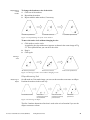
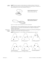
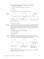

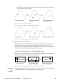
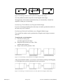
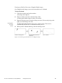

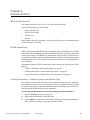
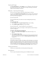


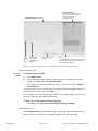


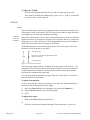


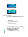

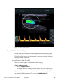
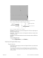


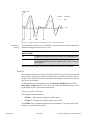

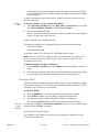

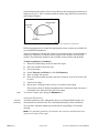


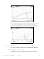


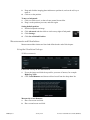
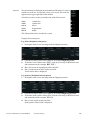


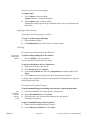
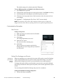
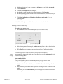


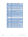


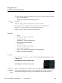
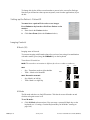


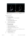


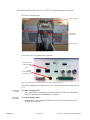
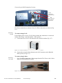
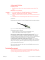


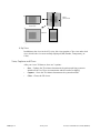

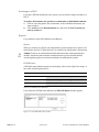


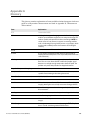

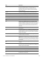


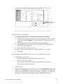
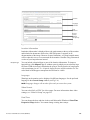

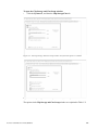

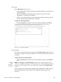


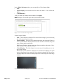
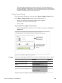


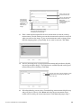
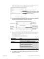

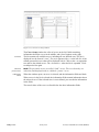

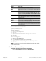
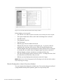
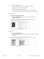
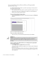


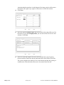
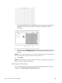
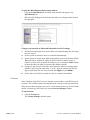
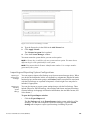

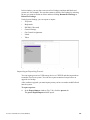
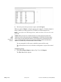
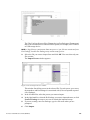
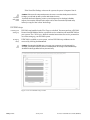
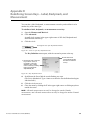

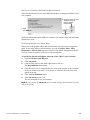

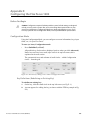
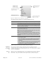
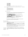
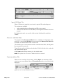
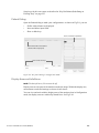
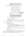
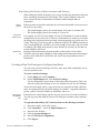


![4 Click [OK] - Toshiba America Business Solutions](http://vs1.manualzilla.com/store/data/005818130_1-6da0751aebf4d6c87686321c2c4e7e3a-150x150.png)