1
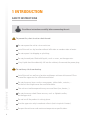
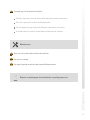
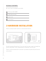
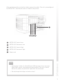
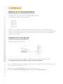
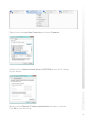
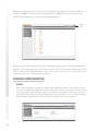
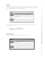
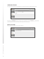
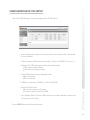
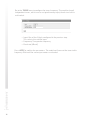
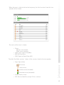
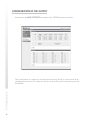
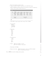
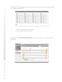
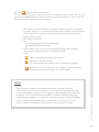
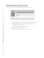
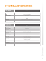
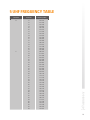
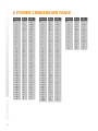
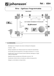
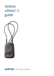
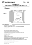
user manual Colosseum 8500D No part of this manual may be copied, reproduced, transmitted, transcribed or translated into any language without permission. Unitron reserves the right to change the specifications of the hardware and software described in these manuals at any time. Unitron can not be held liable for any damages resulting from the use of this product. Specifications are subject to change without notice. 11/11 © Unitron - Frankrijklaan 27 - B-8970 Poperinge - Belgium T +32 57 33 33 63 F +32 57 33 45 24 email [email protected] www.johansson.be - www.unitrongroup.com 2 CONTENTS 1INTRODUCTION safety instructions.................................................................................................................... 4 package contents..................................................................................................................... 6 2 HARDWARE INSTALLATION............................................................................................. 6 3WEBGUI minimal system requirements................................................................................................. 8 logging into the device............................................................................................................. 8 general configuration............................................................................................................. 10 about..................................................................................................................................... 10 global.................................................................................................................................... 11 factory reset........................................................................................................................ 11 firmware upgrade............................................................................................................... 12 module restart..................................................................................................................... 12 configuration of the input...................................................................................................... 13 configuration of the output.................................................................................................... 16 configuration of the MPEG setting....................................................................................... 20 3 TECHNICAL SPECIFICATIONS........................................................................................ 21 4 CONDITIONS OF WARRANTY......................................................................................... 22 5 UHF FREQUENCY TABLE................................................................................................... 23 6 POWER CONVERSION TABLE......................................................................................... 24 3 1INTRODUCTION SAFETY INSTRUCTIONS Read these instructions carefully before connecting the unit To prevent fire, short circuit or shock hazard: Do not expose the unit to rain or moisture. Install the unit in a dry location without infiltration or condensation of water. Do not expose it to dripping or splashing. Do not place objects filled with liquids, such as vases, on the apparatus. If any liquid should accidentally fall into the cabinet, disconnect the power plug. To avoid any risk of overheating: Install the unit in a well aery location and keep a minimum distance of 15 cm around the apparatus for sufficient ventilation. Do not place any items such as newspapers, table-cloths, curtains,… on the unit that might cover the ventilation holes. The unit must not be exposed to any source of heat (sun, heater,...). Do not place any naked flame sources, such as lighted candles, on the apparatus. 4 Do not install the product in a dusty place. Use the apparatus only in moderate climats (not in tropical climates). Respect the minimum and maximum temperature specifications. To avoid any risk of electrical shocks: Connect apparatus only to socket with protective earth connection. The mains plug shall remain readily operable. Pull out power plug to make the different connections of cables. To avoid electrical shock, do not open the housing of adapter. Maintenance Only use a dry soft cloth to clean the cabinet. Do not use solvent. For repairing and servicing refer to qualified personnel. Dispose according your local authority’s recycling processes 5 PACKAGE CONTENTS Be sure all items listed below are included: 1 Colosseum (Ref. 8500D) 1 CAT6 ethernet cable 1 power cord 1 user manual 2HARDWARE INSTALLATION The unit can be placed on a table (1), or mounted to the wall (2). 1 2 For wall-mounting, drill two holes, 23 cm apart and insert two screws (min length from wall to screw head is 12 mm, and diameter of screw head is max 11.5 mm) . The unit can be mounted with its connectors up or down, but preferrably with the connectors down. 6 After positioning of the unit (wall or table), connect the cables. The unit is preconfigured for ASTRA 19.2°. Connect the cables as shown in the picture: 5 1 2 3 4 1 ASTRA 19.2° Vertical Low 2 ASTRA 19.2° Horizontal Low 3 ASTRA 19.2° Vertical High 4 ASTRA 19.2° Horizontal High 5 Power cord NOTES • Connect the 4 cables of a Quad/Quattro LNB to prevent alarm messages. Some LNB’s require a lot of power to work properly. The unit is able to deliver this power, only when the 4 polarities are connected. • Do not change the bridges or load resistors! 7 3WEBGUI MINIMAL SYSTEM REQUIREMENTS The WebGUI is supported by the following web browsers (and newer versions of these browsers): •Chrome 4 •Safari 3.1 •Firefox 3.6 •Explorer 8 •Opera 10.6 When using a different browser, we cannot guarantee a correct functioning of the interface. The webGUI will indicate this with a warning message. This message will be shown every time you browse to another menu item. Please install one of the above browsers to avoid this. LOGGING IN TO THE DEVICE Connect the module to your PC. The module will obtain an IP address from your PC. For this operation to work, it is important that the PC is NOT set with a manual IP address! Set the adapter to obtain an automatic IP address as explained in the following procedure (for Microsoft Windows 7®) Navigate to the Control Panel (Start Control Panel). Enter the Network and Sharing Center and go to the Adapter Settings. 8 Right-click on the Local Area Connection and choose Properties. Double click on Internet Protocol Version 4 (TCP/IPv4) to enter the IP settings of your adapter. Make sure the ‘Obtain an IP address automatically’ checkbox is selected. Click OK to save the settings. 9 Open your network browser, and surf to the name of the module. The name of the first module is mod1, the name of the second module is mod2. You will now log in to the module. After logging in, the Summary window appears. status ‘LED’ On this screen, you see all the services, streamed by this module. The type of module, the status and the language are visible on every screen. In the picture above, the status ‘LED’ is green, indicating that there are no alarms. The alarm status is shown when you move over the status ‘LED’ with your mouse. GENERAL CONFIGURATION ABOUT The ‘about’ tab gives some basic information about the device. Here, you can find the serial number, the software version and release date. These are useful to check if you have the latest software version installed on your device. New versions can be found on the website. If you experience serious problems, you can download a troubleshoot information file. Save this file, and mail it to us for analysis. 10 GLOBAL Here you can configure the hostname of the module. This name can be used to access the module by simply typing it into your browser as the address and surf to it. This is more convenient than using the IP address. Just enter ‘http://hostname’ into your favorite browser (not case sensitive) and press enter: FACTORY RESET All settings can be reset to default by means of a factory reset. 11 FIRMWARE UPGRADE To upgrade the firmware of the device, click the Firmware upgrade menu item. Click on the BROWSE button, and open the upgrade file. Click UPLOAD to send the file to the device, this will install the new firmware on the device. MODULE RESTART Press this menu item to restart the module. 12 CONFIGURATION OF THE INPUT Go to the LNB Settings menu to configure the 4 LNB inputs. • Input: Sequence number of the input (also indicated on the front of the actual module) • Label: custom label for each input (e.g. V low, or ASTRA 19.2 V Low,…) • Voltage: The LNB voltage to select the polarization 13V: Vertical polarization 18V: Horizontal polarization • Tone: LNB tone to select low/high band ON: high band OFF: low band • DiSEqC®: control of a DiSEqC® switch (A/B/C/D) • Band: Satellite band Ku-band: common in Europe C-band: mostly used in the USA • Ext. Voltage: Add 1V to the LNB voltage to compensate the cable losses for long coaxial cables. Press APPLY to confirm the parameters. 13 Go to the TUNER menu to configure the tuner frequency. The modules have 4 independent tuners, which can be assigned to every input, thanks to a built-in multiswitch. • • • Input: One of the 4 labels configured in the previous step. This selects the satellite input. Frequency: Transponder frequency Baud rate [kBaud] Press APPLY to confirm the parameters. The module will now set the tuner to this frequency. Wait until the correct parameters are loaded. 14 When the tuner is able to lock on the frequency, the list of services from this transponder will be shown. The status of the tuner is shown. • Status: Green: tuner locked Red: tuner unlocked • Level: input signal level [dBm] • BER: Bit Error Rate • SNR: Signal to Noise Ratio [dB] The table ‘Available services’ shows all the services found in the transponder. • Type: Type of data TV service radio service locked service (encoded) unlocked service (decoded) • Name: Service name • SID: Service Identifier (unique ID for a service) 15 CONFIGURATION OF THE OUTPUT Navigate to the MUX SETTINGS to configure the COFDM output parameters. The 4 multiplexes are adjacent, and only the frequency of the first mux needs to be configured, the others will automatically be set according to this frequency and the bandwidth. 16 • • Mux: The multiplex number (1 to 4) Frequency [kHz]: multiplex frequency in the VHF-UHF range: 47000 to 830000 kHz. When entering a frequency outside this frequency range, an error will be shown to the user. • Level [dBm]: signal output level (range: -40 to -25 dBm) • Constellation: QPSK 16-QAM 64-QAM • Code Rate: 1/2 2/3 3/4 4/5 5/6 7/8 • Guard interval: 1/32 1/16 1/8 1/4 • Status: ON: the multiplex is active OFF: the multiplex is not active • Bandwidth: 6/7/8 MHz • Spectral inversion: ON: the frequency spectrum will be inverted OFF: no frequency inversion Press APPLY to save the settings to the module. 17 The TSID & LCN parameters are used to setup the logical channel numbering (channel sequence on the TV). • TSID: Transport Stream Identifier • LCN: Logical Channel Number Navigate to the SERVICE ASSIGNMENT menu to setup the TV and radio services at the output. 18 Press the button to add a new service. A list of available services (from all 4 tuners) will appear on the screen. Click on the service to be added and wait until the service is loaded into the list. The list will be refreshed and the added service will appear. • LCN (Logical Channel Number): A logical channel number, also known as virtual channel, is a channel designation which differs from that of the actual channel (or range of frequencies) on which the signal travels. • Name: Service name • SID: Service Identifier • On: Check to enable the service at the output. Uncheck to disable the service. • CAM: Check to pass the service through the CAM card. Encoded services will automatically pass through the CAM. • Icons: add a new program to the list of services update the current service, this icon will become active if some setting has changed delete the service from the list, pressing this icon will remove the program permanently (you can add it again) NOTES The bitrate bar shows the current bitrate of the selected multiplex. The number of services per multiplex is restricted to 8. Depending on the model, the module disposes of 4 multiplexes, each capable of transporting 8 programs. The maximum bitrate per MUX is 32 Mbps (depending on the modulation parameters). It is however advisable to keep a buffer of 4 Mbps, to prevent possible overflow (bitrate of services can fluctuate in time). Select another multiplex by clicking on the tabs on top of the page. 19 CONFIGURATION OF THE MPEG SETTINGS This menu item is only visible with modules having a DVB-S 2 input. • Forward EPG tables: Forward Electronic Program Guide tables to the TV’s. • CAS forwarding: Forward the Control Access System tables (CAT, EMM, ECM) to descramble the programs with a set-top box. CAT: Conditional Access Table EMM: Entitlement Management Message ECM: Entitlement Control Message • Block others: Block private data. • PID share: Enable sharing of the PES, PCR and ECM. 20 3 TECHNICAL SPECIFICATIONS SAT INPUT NB OF INPUT TUNER DVB-S(2) 8 8 tuners (8 transponders) FREQUENCY RANGE 950-2150 MHz LEVEL -55 to -25 dBm BANDWIDTH 36 MHz MODULATION DVB-S2: QPSK, 8PSK / DVB-S: QPSK DC REMOTE POWER AT RF INPUT TV OUTPUT NB OF OUTPUT FREQUENCY RANGE MULTIPLEXES CHANNEL BANDWIDTH MODULATION OFDM MODE SPECTRAL INVERSION 13V/18V/22kHz DVB-T 1 with 1 loop-through (-1,5 dB loss) 47-862 MHz 8 7 MHz (VHF) / 8 MHz (UHF) QPSK, 16-QAM, 64-QAM 2K on/off OUTPUT LEVEL 68 to 83 dBµV adjustable CONNECTORS RF: 20 x ‘F’ female Management: 2 x RJ-45 DC: ‘banana sockets’ POWER SUPPLY 15 VDC CONSUMPTION 3A OPERATING TEMPERATURE DIMENSIONS 0 to +40°C 280 x 260 x 150 mm 21 4 CONDITIONS OF WARRANTY PERIOD OF WARRANTY Unitron N.V. warrants the product as being free from defects in material and workmanship for a period of 24 months starting from the date of production indicated on it. See note below. If during this period of warranty the product proves defective, under normal use, due to defective materials or workmanship, Unitron N.V, at its sole option, will repair or replace the product. Return the product to your local dealer for reparation. THE WARRANTY IS APPLIED ONLY FOR DEFECTS IN MATERIAL AND WORKMANSHIP AND DOES NOT COVER DAMAGE RESULTING FROM •Misuse or use of the product out of its specifications. •Installation or use in a manner inconsistent with the technical or safety standards in force in the country where the product is used. •Use of non-suitable accessories (power supply, adapters ...). •Installation in a defect system. •External cause beyond the control of Unitron N.V. such as drop, accidents, lightning, water, fire, improper ventilation… THE WARRANTY IS NOT APPLIED IF •Production date or serial number on the product is illegible, altered, deleted or removed. •The product has been opened or repaired by a non-authorised person. NOTE Date of production is MMYY format, example 0411 = April 2011. For the serial number barcodes, the date corresponds to the 4 first numbers. 22 5 UHF FREQUENCY TABLE TV band Channel Frequency MHz IV 21 22 23 24 25 26 27 28 29 30 31 32 33 34 35 36 37 38 39 40 41 42 43 44 45 46 47 48 49 50 51 52 53 54 55 56 57 58 59 60 61 62 63 64 65 66 67 68 69 470-478 478-486 486-494 494-502 502-510 510-518 518-526 526-534 534-542 542-550 550-558 558-566 566-574 574-582 582-590 590-598 598-606 606-614 614-622 622-630 630-638 638-646 646-654 654-662 662-670 670-678 678-686 686-694 694-702 702-710 710-718 718-726 726-734 734-742 742-750 750-758 758-766 766-774 774-782 782-790 790-798 798-806 806-814 814-822 822-830 830-838 838-846 846-854 854-862 V 23 6 POWER CONVERSION TABLE 24 μV 75 Ω dBμV dBm 1 1.5 2 2.5 3 3.5 4 4.5 5 6 7 8 9 10 15 20 25 30 35 40 45 50 60 70 80 90 100 150 200 250 300 350 400 450 500 600 700 800 900 0 3.5 6 8.0 9.5 11 12 13 14 15.5 17 18 19 20 23.5 26 28 29.5 31 32 33 34 35.5 37 38 39 40 43.5 46 48 49.5 51 52 53 54 55.5 57 58 59 -109 -105.5 -103 -101 -99.5 -98 -97 -96 -95 -93.5 -92 -91 -90 -89 -85.5 -83 -81 -79.5 -78 -77 -76 -75 -73.5 -72 -71 -70 -69 -66.5 -63 -61 -59.5 -58 -57 -56 -55 -53.5 -52 -51 -50 mV 75 Ω 1 1.5 2 2.5 3 3.5 4 4.5 5 6 7 8 9 10 15 20 25 30 35 40 45 50 60 70 80 90 100 150 200 250 300 350 400 450 500 600 700 800 900 1000 dBμV dBm V 75 Ω dBμV dBm 60 63.5 66 68 69.5 71 72 73 74 75.5 77 78 79 80 83.5 86 88 89.5 91 92 93 94 95.5 97 98 99 100 103.5 106 108 109.5 111 112 113 114 115.5 117 118 119 120 -49 -45.5 -43 -41 -39.5 -38 -37 -36 -35 -33.5 -32 -31 -30 -29 -25.5 -23 -21 -19.5 -18 -17 -16 -15 -13.5 -12 -11 -10 -9 -5.5 -3 -1 +0.5 +2 +3 +4 +5 +6.5 +8 +9 +10 +11 1 1.5 2 2.5 3 3.5 4 4.5 5 6 7 8 9 10 120 123.5 126 128 129.5 131 132 133 134 135.5 137 138 139 140 +11 +14.5 +17 +19 +20.5 +22 +23 +24 +25 +26.5 +28 +29 +30 +31 25 26 27 www.unitrongroup.com UNITRON NV Frankrijklaan 27 B-8970 Poperinge Belgium T +32 57 33 33 63 F +32 57 33 45 24 [email protected] www.johansson.be