1
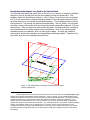
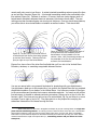
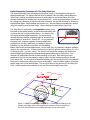
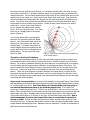
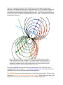
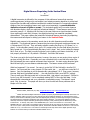
Digital Beacon Pinpointing In the Vertical Plane
by
Dave Barber1
A digital transceiver is defined for the purposes of this article as a beacon that uses two
receiving antennas (orthogonal to one another) and a data processing algorithm to collect and
interpret flux line data with sufficient confidence to enable the beacon to numerically estimate
distance from the transmitting beacon and, much more importantly, to provide direction
indication via a set of lights or arrows. This technique applies only to modern beacons
with direction display, what you might call directional beacons2. These beacons excel in the
secondary search, i.e., following the flux lines to the near field once a signal has been located.
Upon reaching the near field, however, the digital technology has remained completely
underutilized. This paper realizes the potential of directional beacon pinpointing by explaining
the reasons and techniques for taking your beacon to the Vertical Plane.
Digital’s great success in the secondary search has to do with dimensions and favorable
orientation. The directional beacons, because they have two orthogonal receiving antennas, are
a 2-dimensional (2-D) tool. They are keenly suited to reading flux lines in a 2-D space (i.e., a
plane). In the secondary search, when you’re 30+ meters away, the flux field where you are is
fairly spread out. It’s not an absolutely flat plane, but it’s close. And, you’re holding the beacon
flat in front of you. The field is mostly horizontal, you’re holding your beacon horizontal, a 2-D
tool properly oriented in a 2-D problem. Effortless. Just follow the beacon.
The closer you get to the buried transceiver, however, the more you are moving into a region of
up-down arching flux lines. Eventually you cross a threshold into a near-field zone where the
flux field actually has more vertical movement than horizontal. You start seeing direction lights
flash left and right, you see distance estimates spike. The beacon seems a little confused.
What has happened? You moved. You were in a nice flat 2-D flux field with a nice flat 2-D
beacon. You’ve moved into a very dynamic 3-D flux world, but . . . you still have a nice flat 2-D
beacon. Your first handicap is you’re dimensionally outnumbered 3 to 2. Even worse, however,
the near field hasn’t just added vertical . . . the near-field flux field is now MOSTLY vertical.
There is really very little horizontal info in the near field. And where’s your beacon? Still flat in
front of you, still horizontal? You’re completely missing MOST of the near field data. You’re
dimensionally outnumbered and your orientation is completely wrong! That doesn’t sound
good. But, no worries. This paper will show you how to solve both those problems with a
simple roll of the wrist.
1
2
David B. Barber, Idaho Falls, ID, USA, [email protected] or [email protected]
Modern dual-antenna digital transceivers capable of properly implementing this technique must have true
direction indication (LEDs or arrows in a LCD; these arrows point in different directions) on the forward end of the
beacon, and must have sufficiently precise near-field digital signal processing to detect slight changes in predominant
flux field direction as required to exhibit the Jump Point signature behavior. The Jump Point behavior was first
observed, and further explored ultimately producing this technique, while practicing with the Backcountry Access
Tracker DTS™. In January 2003, both a new MAMMUT Barryvox™ and a new Ortovox X1™ were tested. The
MAMMUT Barryvox™ was found to successfully locate Jump Points all the way down to the direction indication shutoff at 0.3 m (note: under personal configuration options, the direction indication disable was reset to 0.3 m from the
default of 3.0 m). The Ortovox X1™ was found to successfully locate Jump Points in the digital-operative range
between 10 m and the factory-set direction indication disable at 2.0 m.
We’re going to reduce the large 3-D problem to a manageable 2-D problem (a single plane in
space) and we’re going to show you how to orient your beacon in that 2-D plane for quick
pinpointing. As the title indicates, and as this discussion has emphasized, most the action is
vertical (up and down). So, our limited search space, our 2-D plane, is going to be vertical also.
We’re going to find a very specific Vertical Plane and properly orient your beacon in it.
The Vertical Plane
The plane in which everything discussed in this article happens is the Vertical Plane. Each burial
scenario has one Vertical Plane. The Vertical Plane, you will find, is a fairly thin slice of space
(less than half a meter wide) that is full of easy-to-read-and-follow flux data. There are no nulls
or spikes in the Vertical Plane. No beacon confusion in the Vertical Plane. The direction
lights/arrows of your digi beacon are always pointing along the strongest flux line, the distance
readings are always reasonably accurate. You will find you can completely trust your digital
beacon in the Vertical Plane.
Great, so where is the Vertical Plane? This very specific 2-dimensional slice of space is, of
course, vertical, and it passes precisely through the axis of the transmitting antenna of the
buried beacon. We don’t know where that is yet, but the digital beacon knows how to find it.
We find the Vertical Plane by following the digital beacon to the pinpoint line.
We Want the Vertical Plane, But First . . . the Pinpoint Line
The pinpoint line is the one and only near-field straight line that is on the snow surface and that
directly overlies the axial orientation of the transmitting antenna. It doesn’t really take any
work on your part to find the pinpoint line. The beacon does it for you. But, there is a definite
skill involved, a skill that can only be developed with practice. You have to learn to ignore that
near-field beacon confusion to see the pinpoint line. Your beacon naturally puts you on the
pinpoint line and at that same time it starts throwing you curve balls. You have to learn to
ignore near-field misinformation and “realize the pinpoint line.” Easier said than done.
The secondary search, as you well know, is the activity of following the beacon to the near field
once you’ve picked up a signal. It starts 30+ meters from the buried transceiver with your
beacon flat in your hands, horizontal to the world, and you follow its direction indication along a
path of decreasing distance to the near field. Is the secondary search easy? You bet! The
secondary search is child’s play with a digital beacon. But, seeing the pinpoint line at the end of
the secondary search takes a cool head. The problem, of course, is that the horizontal-oriented
digital beacon in your hand is flooded with vertical data. It will get confused. A direction flash
off to one side, distance readings will spike, more direction flashes both sides. But in spite of
that noise the beacon is mostly showing you a straight line. You must keep a cool head and see
that straight line through the noise.
Some secondary search approaches will straighten up aligned with the pinpoint line as much as
7-10 meters out. Other approaches will still be curving slightly at 3-4 meters. It all depends on
where you first picked up a signal. But, regardless of how late your path straightens out, it will.
And, regardless of the amount of flashing direction and display data, know you’re also getting
enough good information to see the pinpoint line. Be cognizant of figuring out the pinpoint line
throughout the secondary search and practice until you always come in right on the line.
I cannot possibly overemphasize the importance of plenty of “pinpoint line realization practice.”
Enough About the Pinpoint Line, Back to the Vertical Plane
The next step after finding the pinpoint line on the snow, is to envision an imaginary wall that is
straight up into the sky and down into the snow passing through the pinpoint line. This
imaginary wall is the Vertical Plane (Figure 1). Note in Figure 1 how the one and only pinpoint
line3 is on the snow surface overlying the axial orientation of the transmitting antenna (in this
particular drawing it is a horizontal-oriented buried beacon). The transmitting antenna defines
the pinpoint line. The pinpoint line defines the Vertical Plane. There is, clearly, only one plane,
one sliver in space, that contains both the pinpoint line and the transmitting antenna. Only one
Vertical Plane. Take a moment and really envision the plane. As stated previously, everything
else we talk about in this article happens in the Vertical Plane. Note: if you haven’t already
mastered pinpoint line realization, then it is time to stop reading. You must get outside for
some serious “pinpoint line realization and Vertical Plane envisioning practice.” Please don’t go
any further until you have mastered the pinpoint line.
Figure 1: The Vertical Plane; it contains the transmitting antenna
and the pinpoint line.
3
Modern digital beacons naturally lead the searcher into the near-field region on the one and only straight
pinpoint line for almost all transmitting antenna orientations. There is, however, one very specific situation where
resolving the pinpoint line can be less clear, this is with a truly vertical transmitting antenna. Only with the precisely
straight up and down truly vertical antenna is there any potential for trouble in locating the pinpoint line. The
problem with the vertical transmitter is not a lack of a pinpoint line, but rather an infinite number of equally valid
pinpoint lines (because of the vertical axial orientation). Yes, in this particular case, the precisely vertical transmitting
antenna, my statement “there is only one pinpoint line” is not correct. But no worries, with practice you will
recognize this situation and know to automatically apply the techniques of this method which will be to go vertical
and follow flux lines to a position directly over the buried beacon (what will be called the fountain scenario later in
this writeup).
Getting In the Vertical Plane4
Found the pinpoint line. Envisioned an imaginary wall through the pinpoint line. Now, think of
the face of your beacon, the surface that contains the distance readout and the direction
indication, as a framed picture that you want to hang on a wall. Then, hang the picture (your
beacon’s face) on the imaginary wall (the Vertical Plane). Flat against the wall. By “hang the
picture on the wall” we mean hold the beacon in the air, over the pinpoint line, in the Vertical
Plane. Let’s call the end of the beacon face with the set of directional arrows the “top” of the
picture. You can hang the picture upright (directional arrows point to the sky), you can hang
the picture upside down (directional arrows point down at the pinpoint line on the snow), or you
can hang the picture sideways. Through these rotations, however, the face of the beacon
remains flat against the wall. You can slide the picture all over the imaginary wall, to the left or
to the right (i.e., the entire length of the pinpoint line), down to the snow, as high as you can
reach. All good, just keep the picture flat against the wall. Always flat against the wall.
You are now in the Vertical Plane. You have limited your search space to a single plane that
contains the transmitting antenna. You have placed your digital beacon in that very specific
sliver of space. The 2-D tool has been perfectly positioned in a 2-D problem. You don’t realize
it yet, but you’re already almost done.
Digital Pinpointing Technique #1: Follow the Flux Lines of the Vertical Plane
Sure, you’ve followed flux lines before. But, have you ever followed flux lines after having
already limited your search space to a single plane that you knew already contained the
transmitting antenna of the buried beacon?
How do we follow the flux lines of the Vertical Plane? Simply follow the direction indication
along a path of decreasing distance. In practice this means your beacon will nose dive down
into the snow. Give it a try. Start with your beacon flat against the wall at chest height. What
does the direction indication say? One of the arrows is lit up and the beacon is telling you “the
strongest flux line at this exact spot on the imaginary wall is THIS WAY.” So, follow it. Repeat
this from a few other starting points. All paths lead to the snow. Pull out your owner’s manual
and take at look at the drawing of the flux line field. You must know the shape of this field if
you’re going to pull off any flux line technique. You must appreciate that flux lines keep
curving under the snow surface and you must account for that continuing curvature in picking
your probe location. If you know the basic shape of the flux line field around the transmitting
antenna and can maintain disciplined orientation of your beacon in the Vertical Plane, then you
are already on top of this game.
As you practice following flux lines in the Vertical Plane you will find you can “paint” the flux
field of the imaginary wall in your mind just like you could paint a mural on a real wall. Trace a
few flux lines and sweep your hands along those paths to implant the image. You’ll quickly
become familiar with the possibilities. This pattern recognition is easy because these flux line
4
It should be noted that temporary vertical orientation or “tilt” of digital beacons has been mentioned in
some guidance (see, for example, the 1998 Tracker DTS™ User Manual [TrackerManual98.pdf at
http://www.bcaccess.com/techlibrary/trackermanuals.php]) and vertical orientations have long been a principle facet
of advanced analog pinpointing techniques (see, for example, the discussion of analog bracketing in the MAMMUT
Barryvox™ User Manual [user_manual_7_2002.pdf at http://www.barryvox.com/manuals/index_e.html] or Manuel
Genswein’s paper Pinpointing In a Circle - An Effective and Reliable System for the Precise Location of Deep Burials
[http://www.genswein.com/downloads.html]). This method differs from previous search guidance, however, in its
adherence to a strictly defined Vertical Plane passing through the digital-found pinpoint line.
murals really only come in two flavors. A vertical-oriented transmitting antenna sprays flux lines
up and out like a fountain (Figure 2a). A horizontal transmitting antenna lies underneath a flux
line rainbow (Figure 2b). Fountain or rainbow. Of course, there are ninety degrees worth of
buried beacon transitions between these two extremes, but what are those really? They are
nothing more than fountains tipping over turning into rainbows. Once you know these patterns,
you will be able to know buried beacon orientation as well as location. Think about that!
Figure 2a: The flux lines in the Vertical Plane of
a vertical burial look like flux lines being sprayed
up and out like a fountain. Following flux lines
puts you right on top of the buried beacon.
Figure 2b: The flux lines in the Vertical Plane of
a horizontal burial look somewhat like the
buried beacon is lying beneath a flux line
rainbow. Note: Lots of continuing curvature in
the remainder of the flux line path beneath
surface to the buried beacon.
Figures 2c-e show a few of the other flux line fields that you’ll run into in the Vertical Plane.
Fountains, rainbows, or something recognizable between the two.
Figure 2c
Figure 2d
Figure 2e
You are now armed with a very powerful technique for pinpointing with your digital beacon.
Your digi beacon leads you to the pinpoint line, you envision the Vertical Plane and you maintain
disciplined orientation of your beacon in the Vertical Plane. You follow any number of flux lines
to the snow surface and consider their common subsurface endpoint. You need, as with all flux
line techniques, to be able to estimate continuing curvature5 (Unless you’re on top of a flux line
fountain, right? Flux lines put you right on top of a vertical burial, Fig. 2a, and there is no more
curvature if you’re right on top of it!). The probe point is on the pinpoint line overlying the
subsurface intersection of the traced curving flux lines.
5
What exactly have we done here? We applied a technique to get your receiving beacon in a single thin
plane with the transmitting antenna. In so doing you have a chance to follow “clean” flux lines. Want another
easier practice technique to help you learn the curving shape of flux lines? Go to the park, place a transmitting
beacon flat on a picnic table and explore the flux field around that picnic table while you keep your search beacon
oriented horizontal at the height of that picnic table (i.e., transmitting antenna and your beacon are in the
same plane).
Digital Pinpointing Technique #2: The Jump Point Line
The second technique being introduced in this article is built on an altogether new type of
digital-possible data. For reasons that will soon be evident, this new data is being called the
Jump Point. Holding the digital transceiver at chest height in the Vertical Plane, point the
direction-indicating end straight down at the pinpoint line. In this second technique you will not
be rotating the transceiver to follow its direction indication, but you will definitely be observing
the directional lights. Begin walking the pinpoint line. We are sliding the upside-down picture
along the imaginary wall at chest height. We are finding the chest-height Jump Point.
The Jump Point is, specifically, the tangential meeting of the
level path of the search beacon (a level chest-height path) with
a curving flux line from the buried beacon. It is easy to find
with a dual-antenna digital transceiver. For convenience,
mentally label the direction-indicating lights or arrows on the
search beacon in order as #1 through #5. As you approach
the Jump Point, direction indication moves gradually but
confidently to one side; specifically, the beacon’s direction
indication is in the direction from which you are walking.
Beacon itself is still pointed straight down. At the Jump Point, the direction indication suddenly
jumps to the opposite side. It leaps from light #1 to light #5 without touching lights #2, #3, or
#4 along the way. You can’t miss it! The Jump Point reveals the precision with which dualantenna digital signal processing observes the tangential skimming of the flux line. One
moment the predominant flux line is down-trending to the right. But, within just a few
centimeters, the flux line has peaked in height, rolled over and is down-trending to the left.
Think about that. You are now at a tangential meeting with the curving flux line of the Vertical
Plane that is cresting and rolling over at your chest height. Figure 3 depicts location of a chestheight Jump Point in the Vertical Plane. This is a good time to stop and see if I am telling the
truth. Grab a couple beacons and see if you can find a chest-height Jump Point.
Figure 3: Finding the chest-height Jump Point, i.e., the tangential meeting of the
straight chest-height path of the digital search transceiver with the specific flux
line of the Vertical Plane that is cresting and rolling over at chest height.
Now that you know what the Jump Point is (i.e., tangential meeting with a flux line) and you
know what it looks like (i.e., direction indication jumps to the opposite side), we introduce the
Jump Point Line. You can easily locate several Jump Points in the Vertical Plane and over the
pinpoint line at any height (e.g., at the level of your chest, waist, and knee). Jump Points do
exist at all heights over the pinpoint line, they all look the same and they’re all equally easy to
locate. As you find several Jump Points at different heights you will notice that these Jump
Points seem to line up relative to one another. Locate as many Jump Points as you need to
confirm this. In fact, those Jump Points do
form a straight line headed down into the
snow. And, now, the good news. This Jump
Point Line is a straight path to the buried
beacon (Figure 4).
You now are armed with a second useful
technique for pinpointing with your digital
beacon. Your digi beacon leads you to the
pinpoint line, you envision and enter the
Vertical Plane. You locate Jump Points at
several heights above the pinpoint line and
project that Jump Point Line straight to the
buried beacon. You can probe the Jump
Point Line itself.
Figure 4: Jump Points (red stars) form a straight line
to the buried beacon.
Thoughts on Preferred Techniques
With a vertical transmitting antenna, the flux lines are flowing up and out like a fountain and
your quickest location of the victim is to follow flux lines to a position directly over the buried
beacon. For all other orientations following flux lines leads you to a position that is not directly
over the victim and that requires some estimation of continuing curvature of flux lines. The
more horizontal the buried beacon’s antenna (rainbow flux field), the more useful is the Jump
Point Line. In fact, the Jump Point line is straight up and down over the horizontal buried
beacon. There are ninety degrees of variation between the vertical burial (in which the flux
lines place you directly over the buried beacon) and the horizontal burial (for which the Jump
Point Line is directly over the buried beacon) but these situations all become obvious and easily
recognized with a little practice.
My personal recommendation is to learn to flow instantly from pinpoint line to Vertical Plane
and immediately proceed with walking the pinpoint line with downward-pointing beacon looking
for a chest-height Jump Point. Don’t slow down, don’t break stride, just keep going in
one smooth instantaneous move as you walk the pinpoint line. In a fraction of a
second you “realize the pinpoint line,” “envision the Vertical Plane,” roll your wrist to “put your
beacon IN the Vertical Plane” in downward-oriented Jump Point-location posture and go get that
chest-height Jump Point. Mentally mark that chest-height Jump Point on the imaginary wall.
Then quickly check below it, to the left, to the right, for the waist-height Jump Point. Now a
quick assessment: Are those two Jump Points close to one another or spread out,
narrow or wide? If chest and waist Jump Points are within shoulder width (narrow), finish
the Jump Point Line. If chest and waist Jump Points are wide, say twice shoulder width, trace a
couple distance-decreasing flux lines. Between those two extremes? Consider a combination of
both flux lines and a Jump Point Line.
Figure 5 is a rotatable illustration of the Vertical Plane of three separate example burial
scenarios. Each example scenario (blue, orange and green) has a snow surface/pinpoint line
(the longest colored line) and Jump Points (red stars). Two of the scenarios have smaller
colored arrows showing distance-decreasing flux line paths. Two of the scenarios have Jump
Point Lines. Figure 5 is really three separate figures on one sheet. Twist the sheet to see the
three different scenarios.
Figure 5: Rotatable illustration of the Vertical Plane of three entirely separate example
burial scenarios (blue, orange, and green). The longest colored line of each scenario is
the pinpoint line (i.e., the snow surface). Small scenario-colored arrows indicate typical
paths taken if following flux lines. Red stars are Jump Points found at different heights
above the pinpoint line. Large arrows show Jump Point Lines.
How would the BLUE nearly horizontal burial be best located? Jump Points are narrow,
practically right under one another . . . so finish the Jump Point Line. The Jump Point Line is
practically on top of the buried beacon and pointed straight at it.
The ORANGE scenario is a nearly vertical burial. Jump Points are fairly wide. Skip the Jump
Points and follow flux lines to the top of the flux line fountain. Notice I didn’t even draw in the
Jump Point LineS (yes, there are two of them) on the vertical burial scenario.
The GREEN burial scenario is a case where the Jump Points are about shoulder width. You
know there’s some angle to the Jump Point Line but you should go ahead and finish it. See the
Jump Point Line, see its angle, see where it enters the snow. But don’t probe just yet, let’s get
a little more data. Quickly trace a couple distance-decreasing curving flux lines, say from chest
and waist heights, down to the snow. See (in your mind’s eye) the flux lines’ continuing
curvature under the snow. Now, remember your Jump Point Line, remember its
straight-yet-angled path into the snow. Finally, project all those lines mentally and “see” their
intersection under the snow. That’s the buried beacon.
Let the width of that first pair of Jump Points be your guide. Narrow, finish the Jump
Point Line. Wide, follow flux lines to the top of the flux line fountain. For all those cases in
between, remember the straight Jump Point Line and several curving flux lines projections are
always headed to the same subsurface intersection. The below surface intersection of these
various lines is your very precise total Vertical Plane tool.
Conclusion
This article has introduced some new techniques for pinpointing with a directional beacon. This
method requires that the searcher be armed with a direction-indicating multiple-antenna
digital transceiver, that the searcher be able to recognize the near-field pinpoint line on the
snow surface, that she/he be able to envision the Vertical Plane through the pinpoint line and,
finally, that the searcher be disciplined in maintaining placement of the search beacon in the
Vertical Plane. IN the Vertical Plane! Always flat against the imaginary wall.
2-D tool in a 2-D problem.
These “pinpointing” or “fine search” techniques only begin as the secondary search ends by
delivering you to the pinpoint line. Realizing the pinpoint line is the crux, the place where you
make it or miss it.
As the secondary search ends and you know you’re on the pinpoint line, flow into the Vertical
Plane. Instantly roll your wrist to put your beacon in the Vertical Plane. No worries. Trust your
beacon in the Vertical Plane. You can follow flux lines in the Vertical Plane. Following flux lines
in the Vertical Plane will teach you exactly what flux fields really look like, fountains and
rainbows. Practice. Study the flux field of the Vertical Plane in all burial orientations.
This article also introduced Jump Points, the unique field signature viewable only on the
direction display of the downward-pointing directional transceiver. Your first pair of chest- and
waist-height Jump Points is your guide to the burial orientation. Are the Jump Points wide or
narrow?
Jump Points wide . . . follow flux lines to the top of the fountain.
Jump Points narrow . . . finish the Jump Point Line.
In between, use flux lines and Jump Point Line. This is absurdly easy stuff!
Practice these techniques until your realization of the pinpoint line is instantaneous. Flow from
pinpoint line to Vertical Plane to first pair of Jump Points in one fluid motion. Your wrist rolls
the beacon into the Vertical Plane while your feet keep walking the pinpoint line. If you practice
this you should be verification probing and digging within seconds of reaching the near field.
Practice until it flows.